


Installation Instructions
PS60 - Plasma Swivel Bracket
Design Highlights
-Unique Scissor Design Allows Easy One Handed Operation
-Solid Steel Construction Holds Screen Securely
-Bi-Directional Swivel up to 45 Degrees in Either Direction
Wall Mounts
Thank you for choosing
futureautomation
email info@futureautomation.co.uk tel: +44 (0) 1438 833577 fax: +44 (0) 1438 833565 ISSUE 005

PS60 - Plasma Swivel Bracket
Safety Disclaimer
Important Safety Instructions
Explanation of graphical symbols
-(Electric Shock Symbol) = The lightning flash within an equilateral triangle is intended to alert you to the presence of un-insulated
“dangerous voltage” within the products enclosure that may be of sufficient magnitude to constitute an electric shock to persons
-(Caution Symbol) = The exclamation point within an equilateral triangle is intended to alert you to the presence of important
operating and maintenance (servicing) instructions in the literature accompanying the product
-(Tools Symbols) = The tools symbol within a coloured square are intended to highlight the required tools necessary for correct and
safe installation of the product. These are intended as a
guide only, and it is at the installer’s discretion as to which tools are used.
WARNING: RISK OF ELECTRIC SHOCK, ONLY AUTHORIZED INSTALLERS TO OPEN THE POWER CONTROL BOX.
WARNING: To reduce the risk of fire or electric shock, do not expose electrical parts to rain or moisture, unless the
product has been specifically designed to do so.
Introduction: Safety Information
WARNING: Failure to provide adequate structural strengthening, prior to installation can result in serious personal injury or damage to the
equipment. It is the installer’s responsibility to ensure the structure to which the component is affixed can support the four times the
weight of the component.
WARNING: Do not exceed the weight capacity. This can result in serious personal injury or damage to the equipment. It is the installer’s
responsibility to ensure that the total combined weight of all attached components does not exceed that of the maximum figure stated.
WARNING: Failure to provide adequate structural strength for this component can result in serious personal injury or damage to equipment! It is the installer’s responsibility to make sure the structure to which this component is attached can support five times the combined
weight of all equipment. Reinforce the structure as required before installing the component.
Warnings:
1. Read all technical instructions fully before installation and use. It is the installer’s responsibility to ensure that all
documentation is passed on the end user and read fully before operation.
2. Keep all documentation.
3. Heed all warnings.
4. Follow all technical specifications and instructions during installation.
5. Do not use near water unless the product has been specifically designed to do so.
6. Clean only with a dry cloth.
7. Do not defeat the purpose of the polarized or grounding type plug. A polarized plug has two blades, one wider
than the other. A grounding type plug has two blades and a grounding prong. The wide blade or third prong are
provided for your safety. If the provided plug does not fit your outlet, consult an electrician or contact the
manufacturer.
8. Protect the power cord from being walked on or pinched, particularly at plugs, convenience receptacles, and the
point where the exit from the apparatus.
9. Unplug the apparatus during lightning storms or when unused for long periods of time.
10. Only use attachments/accessories specified by the manufacturer.
11. Refer all servicing to qualified personnel. Servicing is required regularly on an annual basis, when the apparatus is
damaged in any way, liquid has been spilled or objects have fallen into the apparatus, the apparatus has been
exposed to rain or moisture, does not operate normally, or has been dropped.
12. To completely disconnect the apparatus form the AC mains, disconnect the power cord plug from the AC
receptacle on the power control box.
13. To prevent overheating, do not cover the apparatus. Install in accordance with the instructions.
14. UK, Ireland and Hong Kong only – The power cord is supplied with a 13A plug having an earthing pin. The
apparatus is earthed and this pin is not required for safety, merely to operate the safety shutter of mains outlet.
15. No naked flames such as lit candles should be placed on the unit.
16. Observe and follow the local regulations when disposing of batteries.
17. Do not expose the unit to dripping or splashing fluids.
18. Do not place objects filled with liquid, such as vases, on the unit.
19. Do not expose the batteries to excessive heat such as sunshine, fire or the like.
20. For all mounted apparatus, the apparatus should be installed on solid wood, bricks, concrete or solid wood
columns and battens.
21. Always turn off power at source before putting on or taking off parts and cleaning.
22. Do not use outdoors unless marked for outdoor use.
23. Exceeding the weight capacity can result in serious personal injury or damage to equipment.
Caution
Warning
Beware of
Moving Parts
Danger
Electricity
Keep Hands
Clear
Future Sound & Vision trading as Future Automation intend to make this and all documentation as accurate as possible. However, Future
Automation makes no claim that the information contained herein covers all details, conditions or variations, nor does it provide for every
possible contingency in connection with the installation or use of this product. The information contained in this document is subject to
change without prior notice or obligation of any kind. Future Automation makes no representation of warranty, expressed or implied,
regarding the information contained herein. Future Automation assumes no responsibility for accuracy, completeness or sufficiency of the
information contained in this document.
Page 1 of 12 // email info@futureautomation.co.uk tel: +44 (0) 1438 833577 fax: +44 (0) 1438 833565

PS60 - Plasma Swivel Bracket
Contents Page
Introduction
Safety Information 1
Contents 2
Contents 3
Tool Indicator Icons 3
Installation
Parts List 4
Package Contents 4
Stage 1
Before You Start Check 5
Frame Construction 5
Stage 2
Upright Adjustment & Mounting 6
Stage 3
Mounting the Uprights to the Screen 7
Stage 4
Mounting the Screen to the Bracket 8
Stage 5
Screen Positioning 9
Stage 6
Fitting the Bracket to the Wall 10
Stage 7
Fixing the Screen & Uprights to the Bracket 11
Introduction: Contents
Technical Overview 12
Page 2 of 12 // email info@futureautomation.co.uk tel: +44 (0) 1438 833577 fax: +44 (0) 1438 833565

PS60 - Plasma Swivel Bracket
Introduction: Contents / Tool Indicator
Tool Indicator Icons
1. 2. 3. 4. 5. 6.
7.
8.
1. - Drill 3. - Allen Keys 5. - Screwdrivers 7. - Pencil
2. - Tape measure 4. - Spirit Level 6. - Spanners 8. - Saw
This product carries a warranty that covers the cost of labour and spare parts incurred by any defects in materials and workmanship under normal use
during a two year period from date of purchase. Support for any problems that are not hardware faults are excluded from the warranty entitlement.
This warranty does not affect your statutory consumer rights.
The following is excluded from warranty service:
• Malfunctioning caused by misuse or damage, accidental or otherwise, or service modification by persons not authorised by Future Automation,
or the use of any non Future Automation supplied parts;
• Any electrical, or other environmental work external to your Future Automation mechanism including power cuts, surges or lightning strikes;
• Additional items not supplied by Future Automation although they may have been supplied together by the retailer;
• Any 3rd party software products controlling your mechanism;
• Any transfer of ownership. Warranty is provided only to the initial purchaser;
• Compensation for loss of use of the product, and consequential loss of any kind;
• Use of the product over the specified weight capacity;
• Any damage to products during transit that is not checked and notified as “unchecked” or “damaged” upon receipt of delivery.
Product Warranty
Any part of your system that needs to be replaced during a warranty repair becomes the property of Future Automation.
Page 3 of 12 // email info@futureautomation.co.uk tel: +44 (0) 1438 833577 fax: +44 (0) 1438 833565

PS60 - Plasma Swivel Bracket
Package Contents
1 - Wall Bracket
1.1 - Wall Plate
1.2 - Scissor Arms
1.3 - Cross Members
1.4 - Uprights
PS60 Plasma Swivel Bracket for 55” - 70” Screens
Nuts & Bolts Multipack:
A range of nuts, bolts, washers
and spacers to help add in the
mounting for your screen
Installation: Package Contents
1.1
1
1.4
1.3
1.2
Page 4 of 12 // email info@futureautomation.co.uk tel: +44 (0) 1438 833577 fax: +44 (0) 1438 833565

PS60 - Plasma Swivel Bracket
Before You Start
Prior to installation check the following:
-The product is in good condition
-No damage to any parts
-The bracket is in the closed position
Installation: Stage 1
Tighten set screw
to lock in place
Hook uprights over
cross members
Frame Construction
Construct the frame around the PS bracket as shown above. Over lap the uprights
and secure in place by tightening the 4 set screws in the hook details.
Page 5 of 12 // email info@futureautomation.co.uk tel: +44 (0) 1438 833577 fax: +44 (0) 1438 833565

PS60 - Plasma Swivel Bracket
)/$7685)$&(
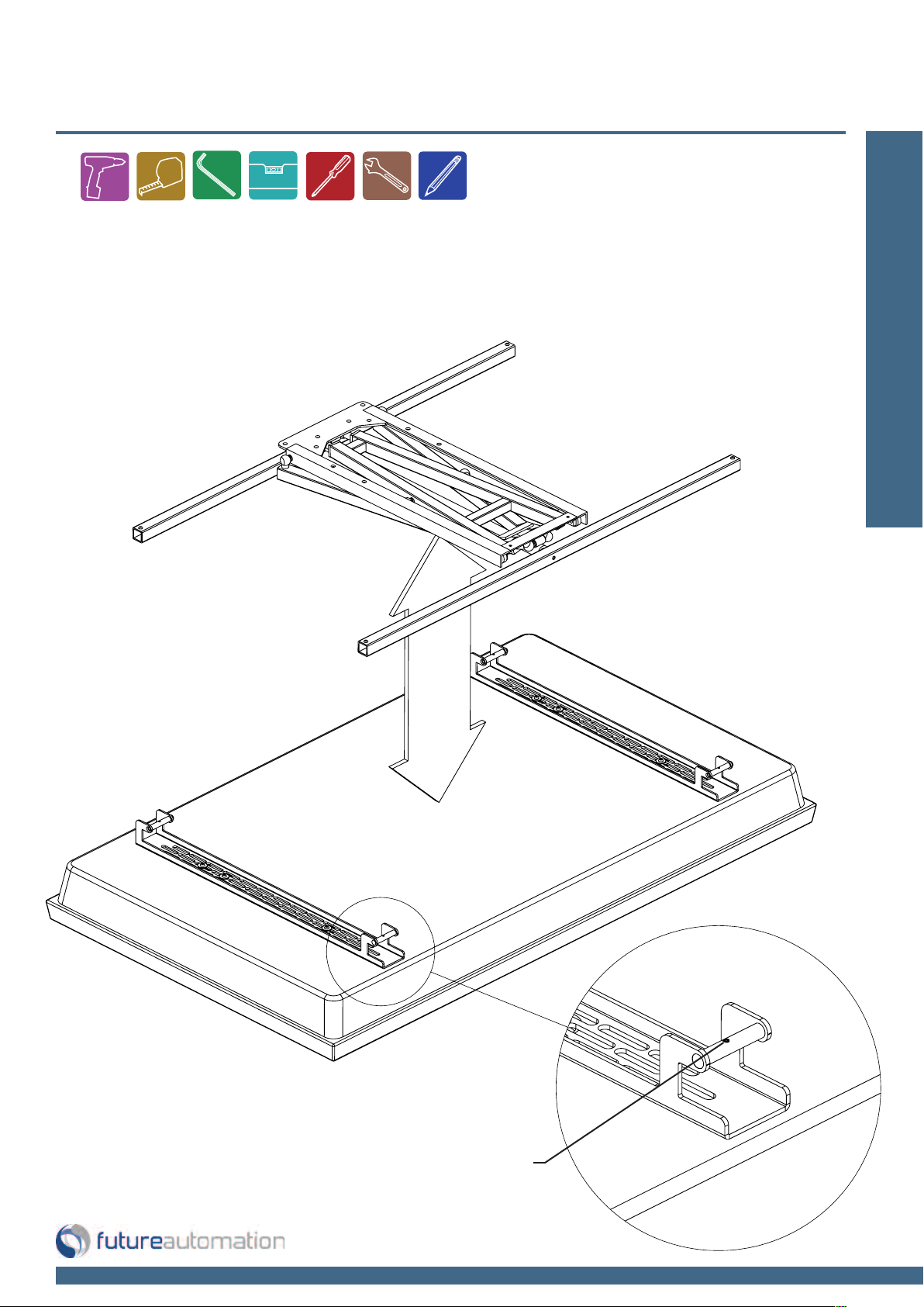
Upright adjustment and mounting
Firstly, place the screen face down on a flat suitable surface, such as carpeted floor.
Take care not to damage the screen.
Flat Surface
Secure the uprights in place on
the back of the screen. Make sure
to get both uprights as level as
possible so the screen is square
when mounted to the wall.
Installation: Stage 2
Once flat, lower the uprights onto the
back of the screen and bolt down to the
mounting points using suitable bolts.
Keep the uprights symmetrical in order to
maintain a central position for the screen.
Page 6 of 12 // email info@futureautomation.co.uk tel: +44 (0) 1438 833577 fax: +44 (0) 1438 833565
PS60 - Plasma Swivel Bracket
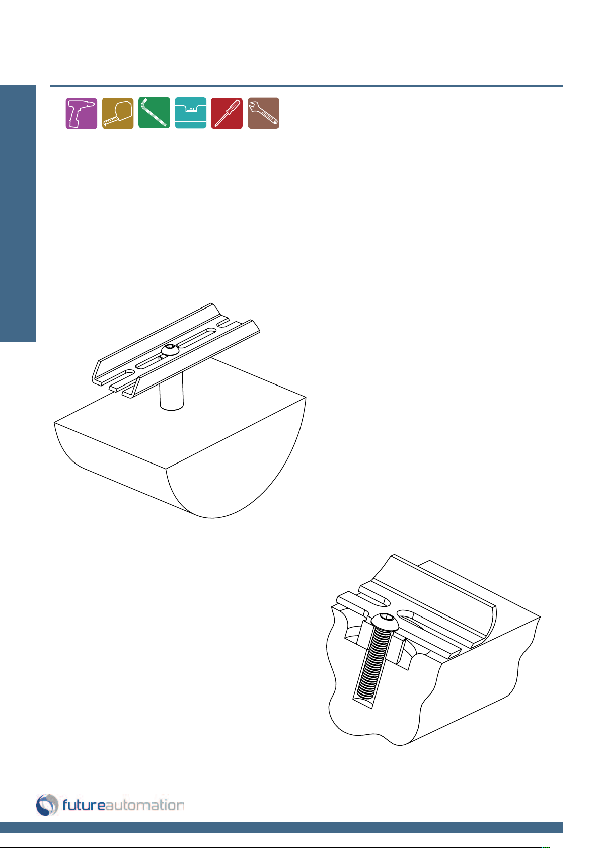
Mounting the uprights to the screen
If the screen has mounting points which are recessed, it will be necessary to
use some of the provided spacers, in order to attach the uprights to the screen.
Installation: Stage 3
It is also recommended that a minimum of 15mm of bolt thread is screwed into
the case of the screen, without bottoming out.
It is also recommended that a
minimum of 15mm of bolt thread
is screwed into the case of the
screen, without bottoming out.
It may be necessary to use spacers even if
the mounting points are not recessed. For
example, if the back panel is not flat, or to
allow for easier electrical connection.
Page 7 of 12 // email info@futureautomation.co.uk tel: +44 (0) 1438 833577 fax: +44 (0) 1438 833565
PS60 - Plasma Swivel Bracket
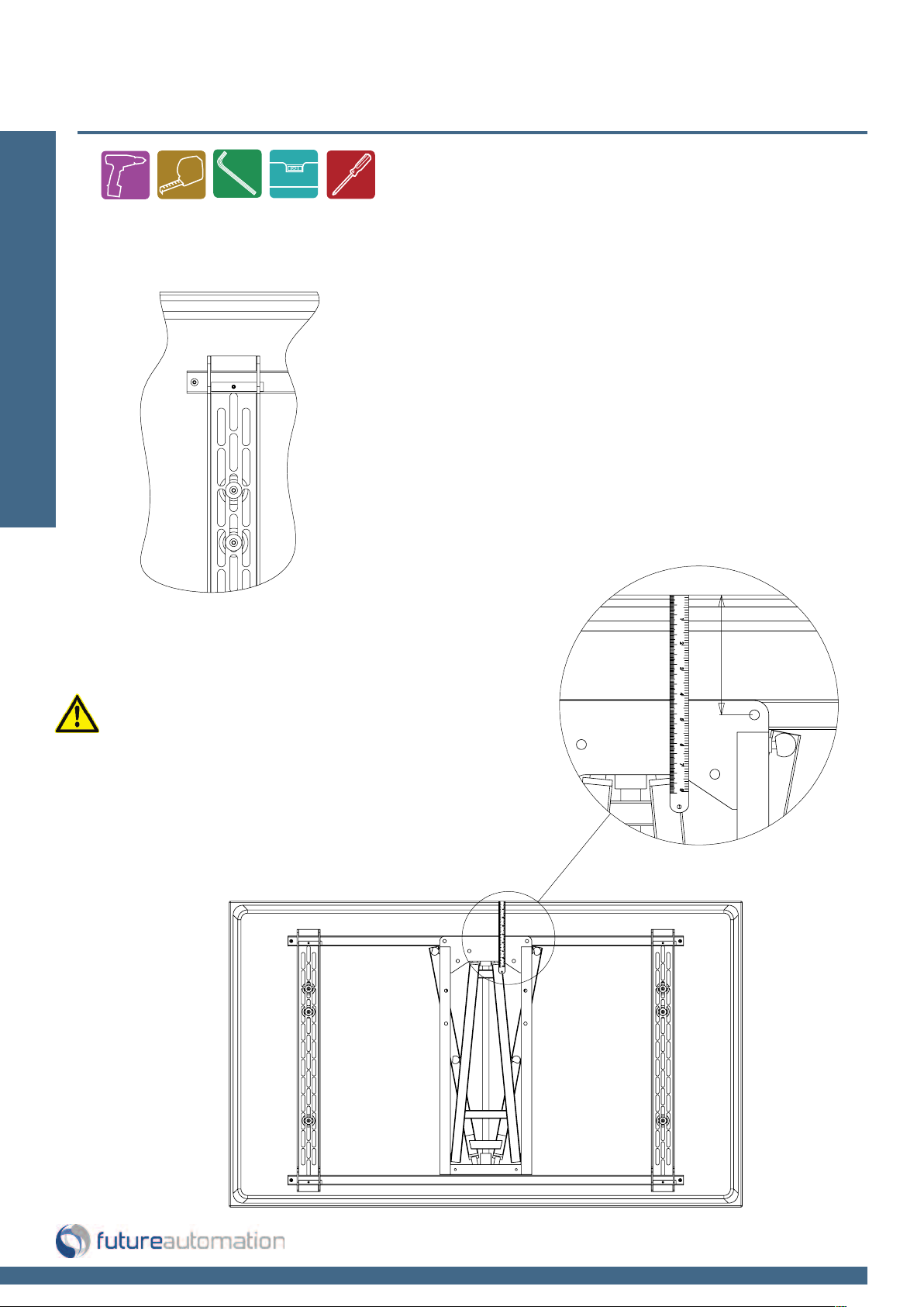
Mounting the frame to the screen
With the screen still face down, lower the bracket down on to the uprights and locate
over the cross members. Tighten up the set screws on the uprights to lock in place when
in the correct position
Installation: Stage 4
Lock in place by
tightening set screws
Page 8 of 12 // email info@futureautomation.co.uk tel: +44 (0) 1438 833577 fax: +44 (0) 1438 833565
PS60 - Plasma Swivel Bracket
Screen positioning
If when the frame is placed on the back of the screen,
Installation: Stage 5
the overlaying slots don't appear to locate with the bolts
on the uprights, it may be necessary to re-position the
uprights or move them left or right.
Take this opportunity to measure the
distance from the top of the screen
down to the top mounting holes of
the wall plate. This will be useful
when gauging the position of the
screen, and hence the position of
the holes in the wall.
Page 9 of 12 // email info@futureautomation.co.uk tel: +44 (0) 1438 833577 fax: +44 (0) 1438 833565
PS60 - Plasma Swivel Bracket
Fitting the Bracket to the Wall
Firstly, remove the bracket from the rear of the screen. Make sure that the uprights
are still left connected to the rear of the plasma screen.
Bearing in mind the relative distance from the top of
the plasma screen to the top mounting holes, place the
wall plate against the wall, and mark where the holes
need to be on the wall. Take care with making sure the
wall plate is level.
Installation: Stage 6
Bracket Position
It is important to remember the limitations of the bracket when deciding on its position on the wall.
The bracket enables a screen to rotate through a maximum of 45 degree clockwise and 45 degree
anti-clockwise from initially being parallel to the wall behind.
Wall Fixings
There are no wall fixings supplied with this product.
The wall plate has 10mm diameter holes for the fixings. Therefore, it is recommended that fixings
of minimum 8mm diameter are used.
It is recommended that either rawlbolts, large diameter plastic wall bolts, or resin anchors are used
to fix this product to the wall.
Suitability of fixings will depend on the type of wall the product will be fixed to.
Page 10 of 12 // email info@futureautomation.co.uk tel: +44 (0) 1438 833577 fax: +44 (0) 1438 833565
PS60 - Plasma Swivel Bracket
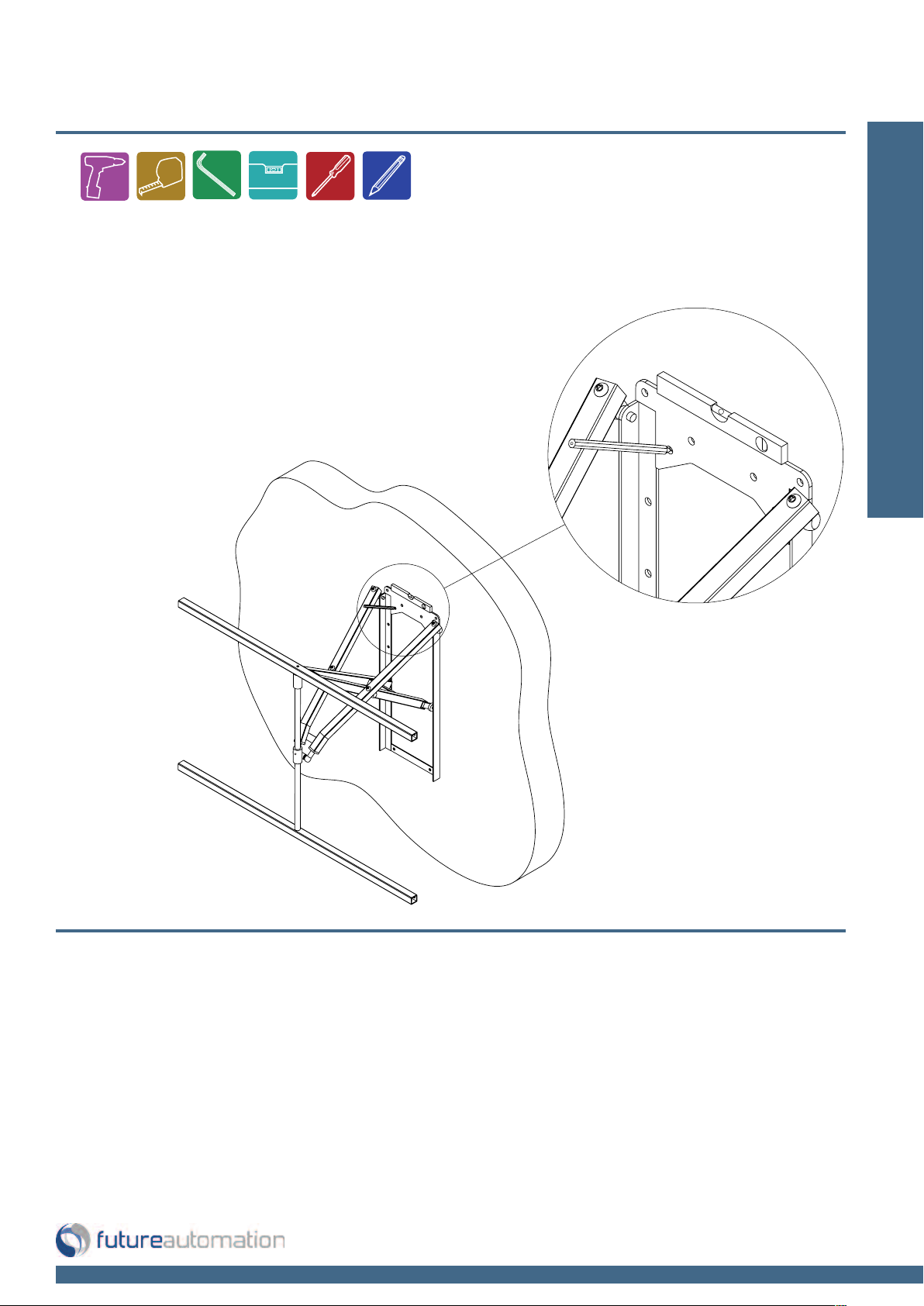
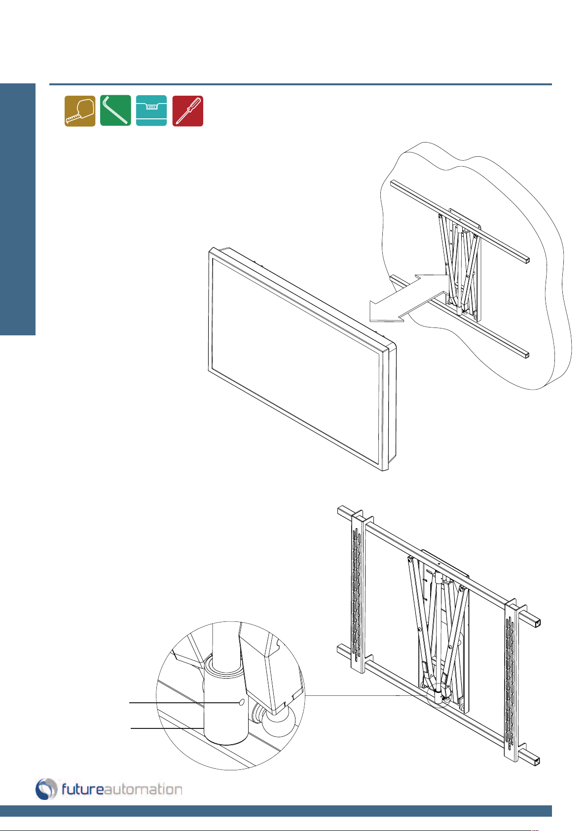
Fixing the Screen & Uprights to the Frame
With the bracket sitting flat against the wall, hook the
screen uprights over the cross members. Make sure
to get the screen symmetrical about the bracket and
then lock into position by tightening the set screws on
the uprights
Installation: Stage 7
UsageTake care when using the PS60 bracket.
If there ever seems to be a fault of some
kind with the mechanism, please consult
Future Automation immediately.
Do not force, or apply excessive loads to
any part of the mechanism.
If the wall bracket is loose when operating you
can add more friction by adjusting the pair of
grub screws located in the sliding collar.
Grub screw
both sides
Sliding collar
Page 11 of 12 // email info@futureautomation.co.uk tel: +44 (0) 1438 833577 fax: +44 (0) 1438 833565
PS60 - Plasma Swivel Bracket
PS60
Product Dimensions
(W,D,H)
1200x80x795mm [47.2x3.1x31.3"]
Weight (Kg) 25Kg [55.1lb]
Movement
Extention From Wall 625mm [24.6"]
Angle Right
45϶
Angle Left
45϶
Max Screen Weight
(W,D,H)
120Kg [264.6lb]
Standard Colour Black
Depth From Wall 80mm [3.1"]
Control Manual
Shipping Details
Dimensions (W,D,H)
760x370x80mm [29.9x14.6x3.1"] &
1230x170x90mm [48.4x6.7x3.5"]
Weight (Kg) 30Kg [66.1lb]
A general technical overview of the PS60 Plasma Swivel Bracket
Technical overview:
Notes...
Page 12 of 12 // email info@futureautomation.co.uk tel: +44 (0) 1438 833577 fax: +44 (0) 1438 833565

Future Automation
Unit 2 Kimpton Enterprise Park
Claggy Road
Kimpton
Hertfordshire
SG4 8HP
United Kingdom
Tel: +44 (0) 1438 833 577
Fax: +44 (0) 1438 833 565
Email: info@futureautomation.co.uk
www.futureautomation.co.uk
 Loading...