

Page 1

Installation Instructions
PM - Projector Mount System
Design Highlights
-Beautiful Anodised Aluminium Finish
-Complete Lead-Screw Adjustment of All Pitches of Angle
-Range of Fixed and Telescopic Poles Available
-Range of Mount Plates for Neatest Possible Mounting
-Hook on, Hook off Installation
Projector Mounts & Drops
Thank you for choosing
futureautomation
email info@futureautomation.co.uk tel: +44 (0) 1438 833577 fax: +44 (0) 1438 833565 ISSUE 004
Page 2
PM - Projector Mount System
Safety Disclaimer
Important Safety Instructions
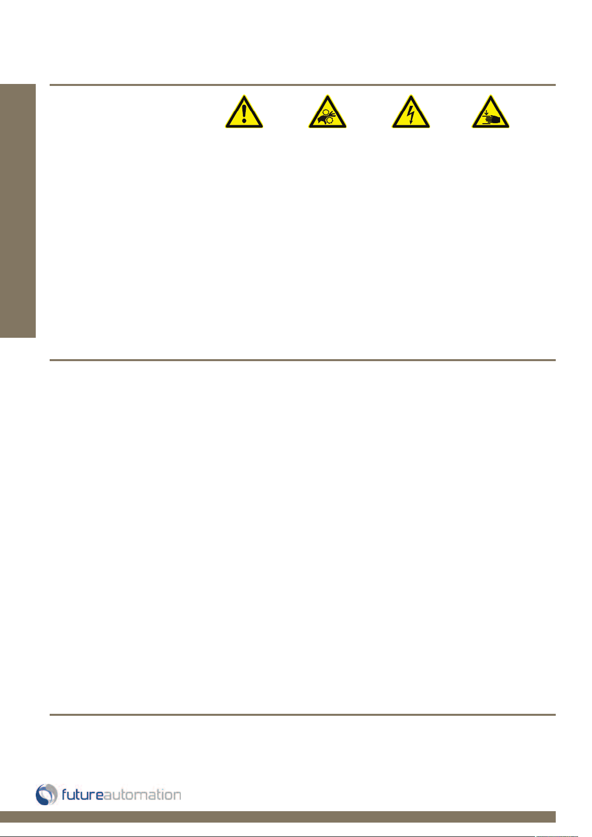
Explanation of graphical symbols
-(Electric Shock Symbol) = The lightning flash within an equilateral triangle is intended to alert you to the presence of un-insulated
“dangerous voltage” within the products enclosure that may be of sufficient magnitude to constitute an electric shock to persons
-(Caution Symbol) = The exclamation point within an equilateral triangle is intended to alert you to the presence of important
operating and maintenance (servicing) instructions in the literature accompanying the product
-(Tools Symbols) = The tools symbol within a coloured square are intended to highlight the required tools necessary for correct and
safe installation of the product. These are intended as a
guide only, and it is at the installer’s discretion as to which tools are used.
WARNING: RISK OF ELECTRIC SHOCK, ONLY AUTHORIZED INSTALLERS TO OPEN THE POWER CONTROL BOX.
WARNING: To reduce the risk of fire or electric shock, do not expose electrical parts to rain or moisture, unless the
product has been specifically designed to do so.
WARNING: Failure to provide adequate structural strengthening, prior to installation can result in serious personal injury or damage to the
equipment. It is the installer’s responsibility to ensure the structure to which the component is affixed can support the four times the
Introduction: Safety Information
weight of the component.
WARNING: Do not exceed the weight capacity. This can result in serious personal injury or damage to the equipment. It is the installer’s
responsibility to ensure that the total combined weight of all attached components does not exceed that of the maximum figure stated.
WARNING: Failure to provide adequate structural strength for this component can result in serious personal injury or damage to equipment! It is the installer’s responsibility to make sure the structure to which this component is attached can support five times the combined
weight of allequipment. Reinforce the structure as required before installing the component.
Warnings:
1. Read all technical instructions fully before installation and use. It is the installer’s responsibility to ensure that all
documentation is passed on the end user and read fully before operation.
2. Keep all documentation.
3. Heed all warnings.
4. Follow all technical specifications and instructions during installation.
5. Do not use near water unless the product has been specifically designed to do so.
6. Clean only with a dry cloth.
7. Do not defeat the purpose of the polarized or grounding type plug. A polarized plug has two blades, one wider
than the other. A grounding type plug has two blades and a grounding prong. The wide blade or third prong are
provided for your safety. If the provided plug does not fit your outlet, consult an electrician or contact the
manufacturer.
8. Protect the power cord from being walked on or pinched, particularly at plugs, convenience receptacles, and the
point where the exit from the apparatus.
9. Unplug the apparatus during lightning storms or when unused for long periods of time.
10. Only use attachments/accessories specified by the manufacturer.
11. Refer all servicing to qualified personnel. Servicing is required regularly on an annual basis, when the apparatus is
damaged in any way, liquid has been spilled or objects have fallen into the apparatus, the apparatus has been
exposed to rain or moisture, does not operate normally, or has been dropped.
12. To completely disconnect the apparatus form the AC mains, disconnect the power cord plug from the AC
receptacle on the power control box.
13. To prevent overheating, do not cover the apparatus. Install in accordance with the instructions.
14. UK, Ireland and Hong Kong only – The power cord is supplied with a 13A plug having an earthing pin. The
apparatus is earthed and this pin is not required for safety, merely to operate the safety shutter of mains outlet.
15. No naked flames such as lit candles should be placed on the unit.
16. Observe and follow the local regulations when disposing of batteries.
17. Do not expose the unit to dripping or splashing fluids.
18. Do not place objects filled with liquid, such as vases, on the unit.
19. Do not expose the batteries to excessive heat such as sunshine, fire or the like.
20. For all mounted apparatus, the apparatus should be installed on solid wood, bricks, concrete or solid wood
columns and battens.
21. Always turn off power at source before putting on or taking off parts and cleaning.
22. Do not use outdoors unless marked for outdoor use.
23. Exceeding the weight capacity can result in serious personal injury or damage to equipment.
Caution
Warning
Beware of
Moving Parts
Danger
Electricity
Keep Hands
Clear
Future Sound & Vision trading as Future Automation intend to make this and all documentation as accurate as possible. However, Future
Automation makes no claim that the information contained herein covers all details, conditions or variations, nor does it provide for every
possible contingency in connection with the installation or use of this product. The information contained in this document is subject to
change without prior notice or obligation of any kind. Future Automation makes no representation of warranty, expressed or implied,
regarding the information contained herein. Future Automation assumes no responsibility for accuracy, completeness or sufficiency of the
information contained in this document.
Page 1 of 14 // email info@futureautomation.co.uk tel: +44 (0) 1438 833577 fax: +44 (0) 1438 833565
Page 3

PM - Projector Mount System
Contents Page
Introduction
Safety Information 1
Contents 2
Contents 3
Tool Indicator Icons 3
Installation
Parts List
Package Contents 4
Stage 1
Assembly Construction 5
Stage 2
Flush Mount 6
Pole Mount 7
Telescopic Pole Mount 8
Wall Mount 9
Stage 3
Mounting the Projector 10
Stage 4
Connecting The PM System To The Locking Collar 11
Stage 5
Projector Adjustment 12
Introduction: Contents
Technical Overview 13
Page 2 of 14 // email info@futureautomation.co.uk tel: +44 (0) 1438 833577 fax: +44 (0) 1438 833565
Page 4

PM - Projector Mount System
Introduction: Contents / Tool Indicator
Tool Indicator Icons
1. 2. 3. 4. 5. 6.
7.
8.
1. - Drill 3. - Allen Keys 5. - Screwdrivers 7. - Pencil
2. - Tape measure 4. - Spirit Level 6. - Spanners 8. - Saw
This product carries a warranty that covers the cost of labour and spare parts incurred by any defects in materials and workmanship under normal use
during a two year period from date of purchase. Support for any problems that are not hardware faults are excluded from the warranty entitlement.
This warranty does not affect your statutory consumer rights.
The following is excluded from warranty service:
• Malfunctioning caused by misuse or damage, accidental or otherwise, or service modification by persons not authorised by Future Automation,
or the use of any non Future Automation supplied parts;
• Any electrical, or other environmental work external to your Future Automation mechanism including power cuts, surges or lightning strikes;
• Additional items not supplied by Future Automation although they may have been supplied together by the retailer;
• Any 3rd party software products controlling your mechanism;
• Any transfer of ownership. Warranty is provided only to the initial purchaser;
• Compensation for loss of use of the product, and consequential loss of any kind;
• Use of the product over the specified weight capacity;
• Any damage to products during transit that is not checked and notified as “unchecked” or “damaged” upon receipt of delivery.
Product Warranty
Any part of your system that needs to be replaced during a warranty repair becomes the property of Future Automation.
Page 3 of 14 // email info@futureautomation.co.uk tel: +44 (0) 1438 833577 fax: +44 (0) 1438 833565
Page 5
PM - Projector Mount System
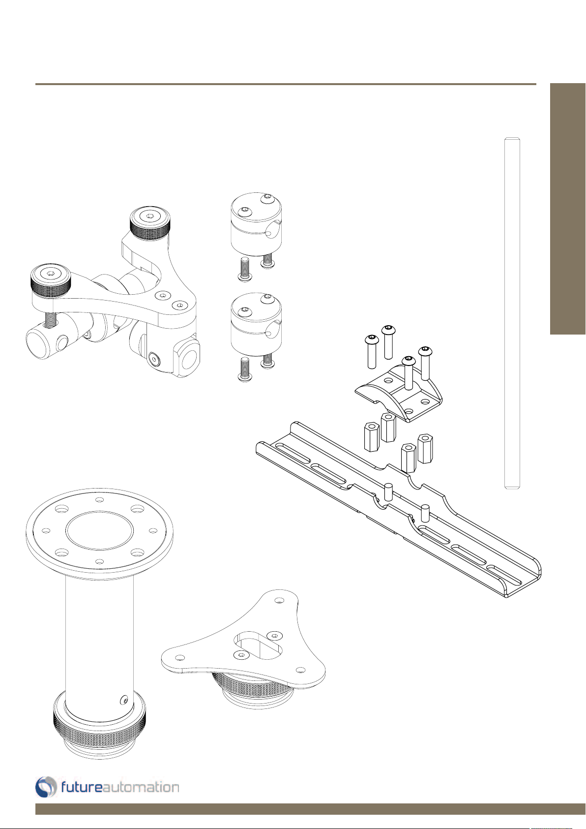
PM Package Contents
You should receive you’re product in 3 separate packs.
Pack 1
Main Body & Front and Rear Bar Clamps
& Standard Projector Mount Kit
Installation: Package Contents
Pack 2
Cross Bar &
Cross Plates
Pack 3
Mount Type Pole or
Flush to Ceiling
Page 4 of 14 // email info@futureautomation.co.uk tel: +44 (0) 1438 833577 fax: +44 (0) 1438 833565
Nuts & Bolts Multipack:
Qty. 8 - 15OD x 6ID x 3mm Plastic spacer
Qty. 4 - M4 x 20mm Button head bolt
Qty. 4 - M4 x 30mm Button head bolt
Qty. 4 - M5 x 20mm Button head bolt
Qty. 4 - M5 x 30mm Button head bolt
Qty. 4 - M6 x 20mm Button head bolt
Qty. 4 - M6 x 30mm Button head bolt
Page 6

PM - Projector Mount System
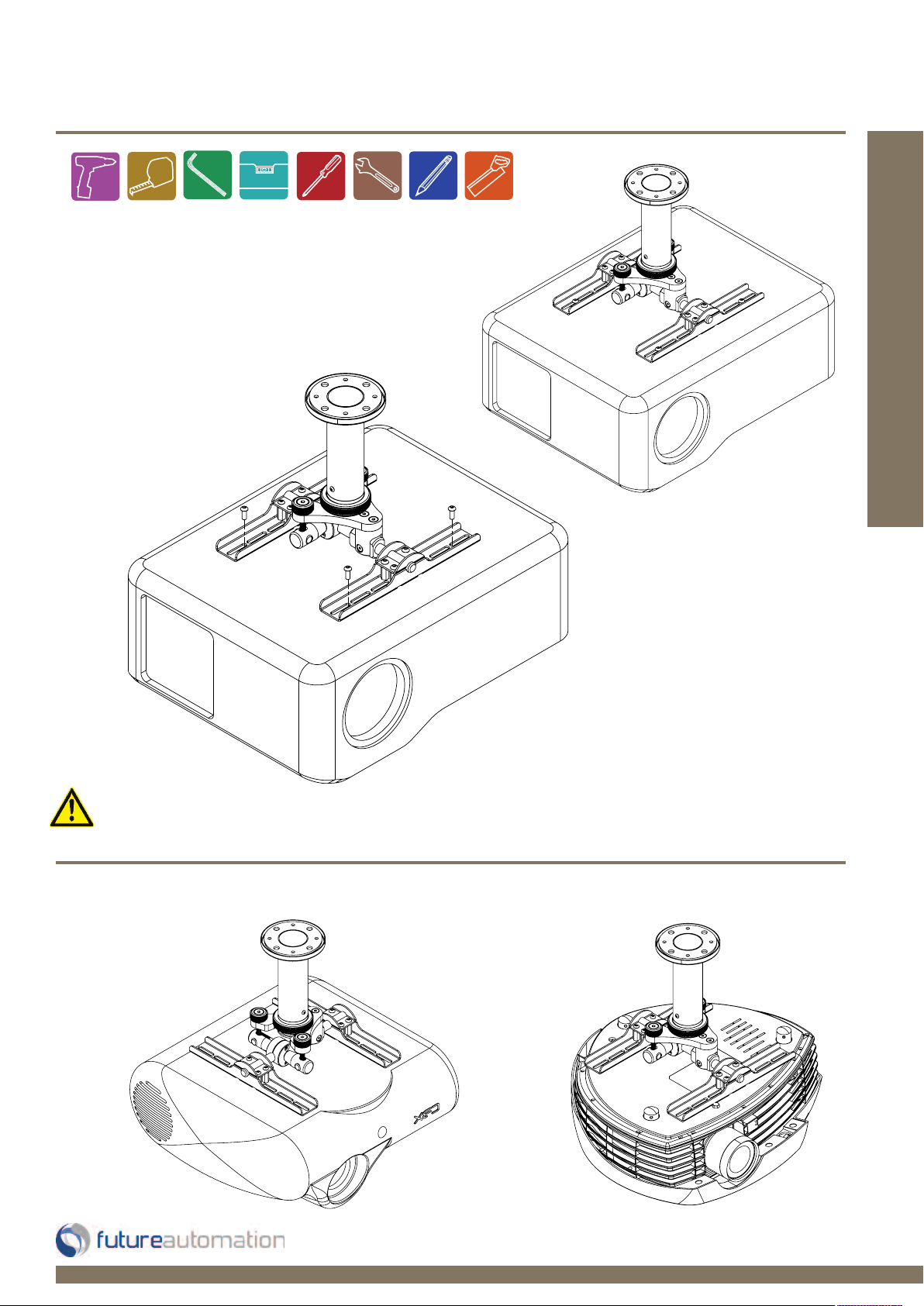
Assembly Construction
Construct the PM System as shown below. Slide the
projector bar through the main body and then fix the
Installation: Stage 1
front and rear bar clamps to each end of the bar.
Position the cross plates to match the mounting pattern
on the projector being used.
Slide the Projector Bar
though the Main Body
Attach the Clamps at both
ends and fix as shown
Page 5 of 14 // email info@futureautomation.co.uk tel: +44 (0) 1438 833577 fax: +44 (0) 1438 833565
Page 7

PM - Projector Mount System
Mark around fixing holes using a
pencil with mount on the ceiling in
Flush Mount
Flat ceiling option - Projector top sits 100mm
from the ceiling with 360 degrees rotation.
the desired location. Make sure that
the mount will be the correct distance
from the projector screen.
Installation: Stage 2
It is the installers responsibility to make sure the mechanism is installed safely and securely
Important Mounting Dimensions
(Note - Drawings are not to Scale)
[3”]
75mm
105mm
[4.1”]
14mm
[0.6”]
14mm
30mm
45mm
[0.6”]
[1.2”]
[1.8”]
[3.9”]
100mm
Page 6 of 14 // email info@futureautomation.co.uk tel: +44 (0) 1438 833577 fax: +44 (0) 1438 833565
3x 7mm [0.3”]
18.5mm
[0.7”]
Page 8

PM - Projector Mount System
Pole Mount
Pole option - Projector top sits 250mm [9.8”], 500 [19.7”] and
750mm [29.5”] away from the ceiling, bespoke sizes can be
manufactured. With 360 degrees rotation available.
Installation: Stage 2
2 - Slide the collar
back to access the
mounting holes
3 - Replace the collar
1 - Move the ‘O’ ring
down the shaft of the
pole to allow the collar
to be pulled back
over the bolt heads
and secure in place
using the ‘O’ ring
10mm [0.4”]
6mm [0.2”]
It is the installers responsibility to make sure the mechanism is installed safely and securely
80mm [3.1”]
80
m
1”]
m [3.
Important Mounting Dimensions
(Note - Drawings are not to Scale)
Heights
*
250 [9.8], 500 [19.7], 750mm
[29.5”] & Bespoke
*
Page 7 of 14 // email info@futureautomation.co.uk tel: +44 (0) 1438 833577 fax: +44 (0) 1438 833565
Page 9

PM - Projector Mount System
Installation: Stage 2
Telescopic Pole Mount
Telescopic pole option - Projector top sits 400 [15.7]
to 700mm [27.6”] and 700 [27.6] to 1300mm [51.2”]
away from the ceiling, bespoke sizes can be manufactured as well. 360 degrees rotation available.
Telescopic Poles are available in 2 standard options:
-400T - 400 [15.7] to 700mm [27.6”]
-700T - 700 [27.6] to 1300mm [51.2”]
Custom spanner for
tightening the locking
collar on the pole.
It is the installers
responsibility to make
sure the mechanism
is installed safely and
securely.
2 - Slide the collar
back to access the
mounting holes
1 - Move the ‘O’ ring
down the shaft of the
pole to allow the collar
to be pulled back
3 - Replace the collar
over the bolt heads and
secure in place using
the ‘O’ ring
Important Mounting Dimensions
(Note - Drawings are not to Scale)
10mm [0.4”]
6mm [0.2”]
80mm [3.1”]
80
m
m [3
.
1”]
Page 8 of 14 // email info@futureautomation.co.uk tel: +44 (0) 1438 833577 fax: +44 (0) 1438 833565
Page 10

PM - Projector Mount System
Wall Mount
Wall option - The arm sits 300mm [11.8”] from the wall to the centre of the locking collar,
bespoke sizes can manufactured. Up to 360 degrees rotation available as long as the
projectors movement isn’t restricted by the wall.
2 - Slide the collar
Installation: Stage 2
1 - Move the ‘O’ ring up the
shaft of the pole to allow the
collar to be pulled back
back to access the
mounting holes
3 - Replace the collar over the
bolt heads and secure in place
using the ‘O’ ring
It is the installers responsibility to make sure the mechanism is installed safely and securely
80mm [3.1”]
6mm [0.2”]
10mm [0.4”]
300mm [11.8”]
Important Mounting Dimensions
(Note - Drawings are not to Scale)
80mm [3.1”]
Page 9 of 14 // email info@futureautomation.co.uk tel: +44 (0) 1438 833577 fax: +44 (0) 1438 833565
Page 11
PM - Projector Mount System
Mount the Projector
Arrange the cross bars so they line up
with the fixing holes on the projector. Use
the fixings provided to secure into place.
Installation: Stage 3
Make sure that the
projector is fixed
securely and safe
Other mounting
possibilities
If you can’t get the mounting plate to fit
the projector, a custom adapter plate
can be designed and manufactured.
Page 6 of 18 // email info@futureautomation.co.uk tel: +44 (0) 1438 833577 fax: +44 (0) 1438 833565
Page 10 of 14 // email info@futureautomation.co.uk tel: +44 (0) 1438 833577 fax: +44 (0) 1438 833565
Page 12

PM - Projector Mount System
Connecting the PM system to the locking collar
Hook the main body on to the bottom of the ceiling mount part of the system.
Tighten the large nut down to secure the main body in place.
Installation: Stage 4
Page 11 of 14 // email info@futureautomation.co.uk tel: +44 (0) 1438 833577 fax: +44 (0) 1438 833565
All of the Locking Collars on the
different options are the same, and
work in the same way.
Page 13

PM - Projector Mount System
Projection Adjustment
Installation: Stage 5
The position of the projector can be pitched
and/or tilted by adjusting 2 knurled knobs
on top of the main body.
1
4 WAY MOVEMENT
Rotate both knobs in SAME DIRECTION to adjust TILT
Rotate both knobs in OPPOSITE DIRECTION to adjust PITCH
2
1 - CCW
2 - CCW
1 - CW
2 - CCW
1 - CW
2 - CW
1 - CCW
2 - CW
Page 12 of 14 // email info@futureautomation.co.uk tel: +44 (0) 1438 833577 fax: +44 (0) 1438 833565
Page 14

PM - Projector Mount System
Mount Type Flush Mount
Sizes (B - Bespoke)
N/A 250 500 750 B 400T 700T 300 B
Product Dimensions (W,D,H) - mm ["]
Main Body
107.5x133x100mm
[4.2x5.2x3.9"]
Weight Kg [lb] 1Kg [2.2lb]
1.2Kg
[2.6lb]
2Kg
[4.4lb]
2.5Kg
[5.5lb]
N/A 2Kg [4.4lb] 3Kg [6.6lb] 1.5Kg [3.3lb] N/A
Maximum Projector Weight Kg [lb] 45Kg [99.2lb]
Standard Colour
Clear or black anodised
aluminium
Depth from Ceiling mm ["] 100mm [3.9"]
250mm
[9.8"]
500mm
[19.7"]
750mm
[29.5"]
N/A
400-700mm
[15.7-27.6"]
700-1300mm
[27.6-51.1"]
300mm [11.8"] N/A
Control Manual
Shipping Details
Dimensions W,D,H - mm ["]
400x300x200mm
[15.7x11.8x7.9"]
Weight Kg [lb] 2Kg [4.4lb]
2.2Kg
[4.9lb]
3Kg
[6.6lb]
3.5Kg
[7.7lb]
N/A 3Kg [6.6lb] 4Kg [8.8lb] 2.5Kg [5.5lb] N/A
Pole Mount
107.5x133x100mm [4.2x5.2x3.9"]
45Kg [99.2lb]
Clear or black anodised aluminium
Manual
Telescopic Pole Mount
PM1 / PM2
Wall Mount
107.5x133x100mm
[4.2x5.2x3.9"]
107.5x133x100mm
[4.2x5.2x3.9"]
45Kg [99.2lb]
45Kg [99.2lb]
Clear or black anodised
aluminium
Clear or black anodised
aluminium
Manual
Manual
400x300x200 (Pole Seperate)
[15.7x11.8x7.9"]
400x300x200 (Pole Seperate)
[15.7x11.8x7.9"]
400x300x200 (Pole Seperate)
[15.7x11.8x7.9"]
A general technical overview of the PM Projector Mount System.
Technical overview:
Page 13 of 14 // email info@futureautomation.co.uk tel: +44 (0) 1438 833577 fax: +44 (0) 1438 833565
Page 15

PM - Projector Mount System
Notes...
Page 14 of 14 // email info@futureautomation.co.uk tel: +44 (0) 1438 833577 fax: +44 (0) 1438 833565
Page 16

Future Automation
Unit 2 Kimpton Enterprise Park
Claggy Road
Kimpton
Hertfordshire
SG4 8HP
United Kingdom
Tel: +44 (0) 1438 833 577
Fax: +44 (0) 1438 833 565
Email: info@futureautomation.co.uk
www.futureautomation.co.uk
 Loading...