

Page 1
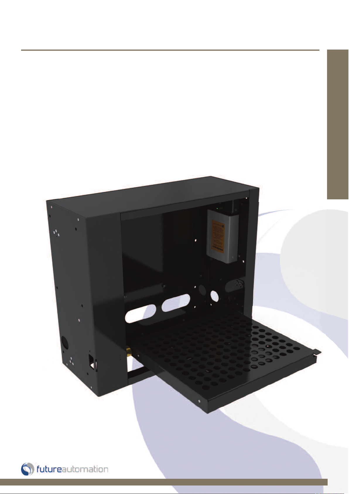
Installation Instructions
PH2 - Projector Hinge
Design Highlights
-Outputs for 3rd Party Product Control
-Cassette Housing for Ease of Installation
-Full Cable Management
-Innovative Design
Projector Mounts & Drops
Thank you for choosing
futureautomation
email info@futureautomation.co.uk tel: +44 (0) 1438 833577 fax: +44 (0) 1438 833565 ISSUE 004
Page 2

PH2 - Projector Hinge
Safety Disclaimer
Important Safety Instructions
Explanation of graphical symbols
-(Electric Shock Symbol) = The lightning flash within an equilateral triangle is intended to alert you to the presence of un-insulated
“dangerous voltage” within the products enclosure that may be of sufficient magnitude to constitute an electric shock to persons
-(Caution Symbol) = The exclamation point within an equilateral triangle is intended to alert you to the presence of important
operating and maintenance (servicing) instructions in the literature accompanying the product
-(Tools Symbols) = The tools symbol within a coloured square are intended to highlight the required tools necessary for correct and
safe installation of the product. These are intended as a
guide only, and it is at the installer’s discretion as to which tools are used.
WARNING: RISK OF ELECTRIC SHOCK, ONLY AUTHORIZED INSTALLERS TO OPEN THE POWER CONTROL BOX.
WARNING: To reduce the risk of fire or electric shock, do not expose electrical parts to rain or moisture, unless the
product has been specifically designed to do so.
WARNING: Failure to provide adequate structural strengthening, prior to installation can result in serious personal injury or damage to the
equipment. It is the installer’s responsibility to ensure the structure to which the component is affixed can support the four times the
Introduction: Safety Information
weight of the component.
WARNING: Do not exceed the weight capacity. This can result in serious personal injury or damage to the equipment. It is the installer’s
responsibility to ensure that the total combined weight of all attached components does not exceed that of the maximum figure stated.
WARNING: Failure to provide adequate structural strength for this component can result in serious personal injury or damage to equipment! It is the installer’s responsibility to make sure the structure to which this component is attached can support five times the combined
weight of all equipment. Reinforce the structure as required before installing the component.
Warnings:
1. Read all technical instructions fully before installation and use. It is the installer’s responsibility to ensure that all
documentation is passed on the end user and read fully before operation.
2. Keep all documentation.
3. Heed all warnings.
4. Follow all technical specifications and instructions during installation.
5. Do not use near water unless the product has been specifically designed to do so.
6. Clean only with a dry cloth.
7. Do not defeat the purpose of the polarized or grounding type plug. A polarized plug has two blades, one wider
than the other. A grounding type plug has two blades and a grounding prong. The wide blade or third prong are
provided for your safety. If the provided plug does not fit your outlet, consult an electrician or contact the
manufacturer.
8. Protect the power cord from being walked on or pinched, particularly at plugs, convenience receptacles, and the
point where the exit from the apparatus.
9. Unplug the apparatus during lightning storms or when unused for long periods of time.
10. Only use attachments/accessories specified by the manufacturer.
11. Refer all servicing to qualified personnel. Servicing is required regularly on an annual basis, when the apparatus is
damaged in any way, liquid has been spilled or objects have fallen into the apparatus, the apparatus has been
exposed to rain or moisture, does not operate normally, or has been dropped.
12. To completely disconnect the apparatus form the AC mains, disconnect the power cord plug from the AC
receptacle on the power control box.
13. To prevent overheating, do not cover the apparatus. Install in accordance with the instructions.
14. UK, Ireland and Hong Kong only – The power cord is supplied with a 13A plug having an earthing pin. The
apparatus is earthed and this pin is not required for safety, merely to operate the safety shutter of mains outlet.
15. No naked flames such as lit candles should be placed on the unit.
16. Observe and follow the local regulations when disposing of batteries.
17. Do not expose the unit to dripping or splashing fluids.
18. Do not place objects filled with liquid, such as vases, on the unit.
19. Do not expose the batteries to excessive heat such as sunshine, fire or the like.
20. For all mounted apparatus, the apparatus should be installed on solid wood, bricks, concrete or solid wood
columns and battens.
21. Always turn off power at source before putting on or taking off parts and cleaning.
22. Do not use outdoors unless marked for outdoor use.
23. Exceeding the weight capacity can result in serious personal injury or damage to equipment.
Caution
Warning
Beware of
Moving Parts
Danger
Electricity
Keep Hands
Clear
Future Sound & Vision trading as Future Automation intend to make this and all documentation as accurate as possible. However, Future
Automation makes no claim that the information contained herein covers all details, conditions or variations, nor does it provide for every
possible contingency in connection with the installation or use of this product. The information contained in this document is subject to
change without prior notice or obligation of any kind. Future Automation makes no representation of warranty, expressed or implied,
regarding the information contained herein. Future Automation assumes no responsibility for accuracy, completeness or sufficiency of the
information contained in this document.
Page 1 of 20 // email info@futureautomation.co.uk tel: +44 (0) 1438 833577 fax: +44 (0) 1438 833565
Page 3

PH2 - Projector Hinge
Contents Page
Introduction
Safety Information 1
Contents 2
Contents 3
Tool Indicator Icons 3
Installation
Parts List 4
Package Contents 4
Stage 1
Testing 5
Before You Start; Check 5
Stage 2
Creating The Void 6
Control Box Set up 6
Stage 3
Installation Of The Mechanism Into The Wall 7
Stage 4
Cable Management & Cladding 8
Stage 5
Securing The Panel 9
Stage 6
Mounting The Front Panel 10
Stage 7
Mounting The Projector 11
Stage 8
Switch Adjustment 12
Electrical Connections
Electrical Connections In The Control Box 13
Contact Closure 14
Warning Lights 15
RS232 15
Wiring & Control Box Details 15
Introduction: Contents
Operations
Remote Control 16
Operation Buttons 16
Changing The Batteries 16
Trouble Shooting 17/18
Technical Overview 19
Page 2 of 20 // email info@futureautomation.co.uk tel: +44 (0) 1438 833577 fax: +44 (0) 1438 833565
Page 4

PH2 - Projector Hinge
Introduction: Contents / Tool Indicator
Tool Indicator Icons
1. 2. 3. 4. 5. 6.
7.
8.
1. - Drill 3. - Allen Keys 5. - Screwdrivers 7. - Pencil
2. - Tape measure 4. - Spirit Level 6. - Spanners 8. - Saw
This product carries a warranty that covers the cost of labour and spare parts incurred by any defects in materials and workmanship under normal use
during a two year period from date of purchase. Support for any problems that are not hardware faults are excluded from the warranty entitlement.
This warranty does not affect your statutory consumer rights.
The following is excluded from warranty service:
• Malfunctioning caused by misuse or damage, accidental or otherwise, or service modification by persons not authorised by Future Automation,
or the use of any non Future Automation supplied parts;
• Any electrical, or other environmental work external to your Future Automation mechanism including power cuts, surges or lightning strikes;
• Additional items not supplied by Future Automation although they may have been supplied together by the retailer;
• Any 3rd party software products controlling your mechanism;
• Any transfer of ownership. Warranty is provided only to the initial purchaser;
• Compensation for loss of use of the product, and consequential loss of any kind;
• Use of the product over the specified weight capacity;
• Any damage to products during transit that is not checked and notified as “unchecked” or “damaged” upon receipt of delivery.
Product Warranty
Any part of your system that needs to be replaced during a warranty repair becomes the property of Future Automation.
Page 3 of 20 // email info@futureautomation.co.uk tel: +44 (0) 1438 833577 fax: +44 (0) 1438 833565
Page 5
PH2 - Projector Hinge
Installation: Package Contents
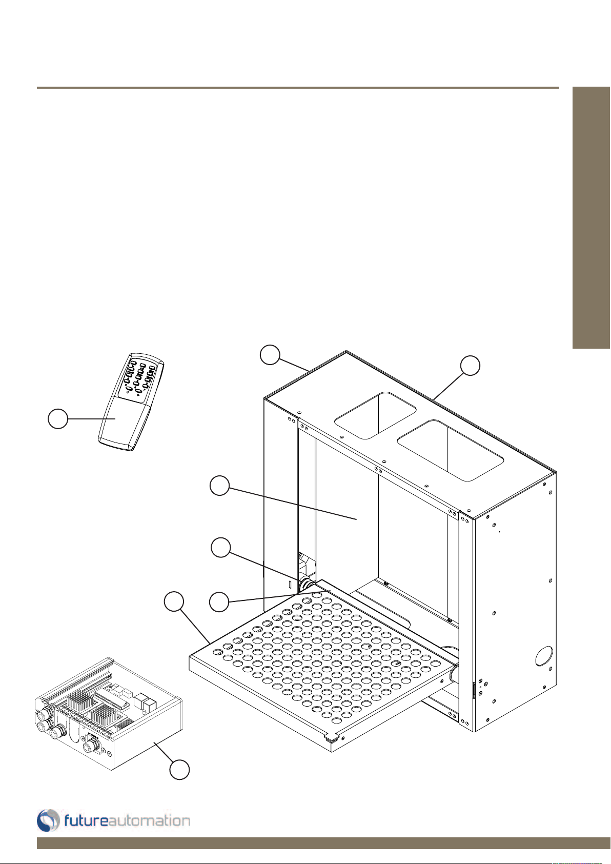
Package Contents
1 - Mechanism
1.1 - Inner Wall Carriage
1.2 - Projector Plate
1.3 - Pivot Hinge
1.4 - Hinge Lock
1.5 - Internal Covers
2 - Control Box
3 - IR Remote Control
Not Shown On Page
4 - x2 AAA Batteries
5 - Multi Pack Of Nuts, Bolts & Washers
6 - Mains Power & Other Leads
3
Nuts & Bolts Multipack:
A range of nuts, bolts, washers and
spacers to help add in the mounting
for your screen
1
1.1
1.2
1.5
1.4
1.3
2
Page 4 of 20 // email info@futureautomation.co.uk tel: +44 (0) 1438 833577 fax: +44 (0) 1438 833565
Page 6
PH2 - Projector Hinge
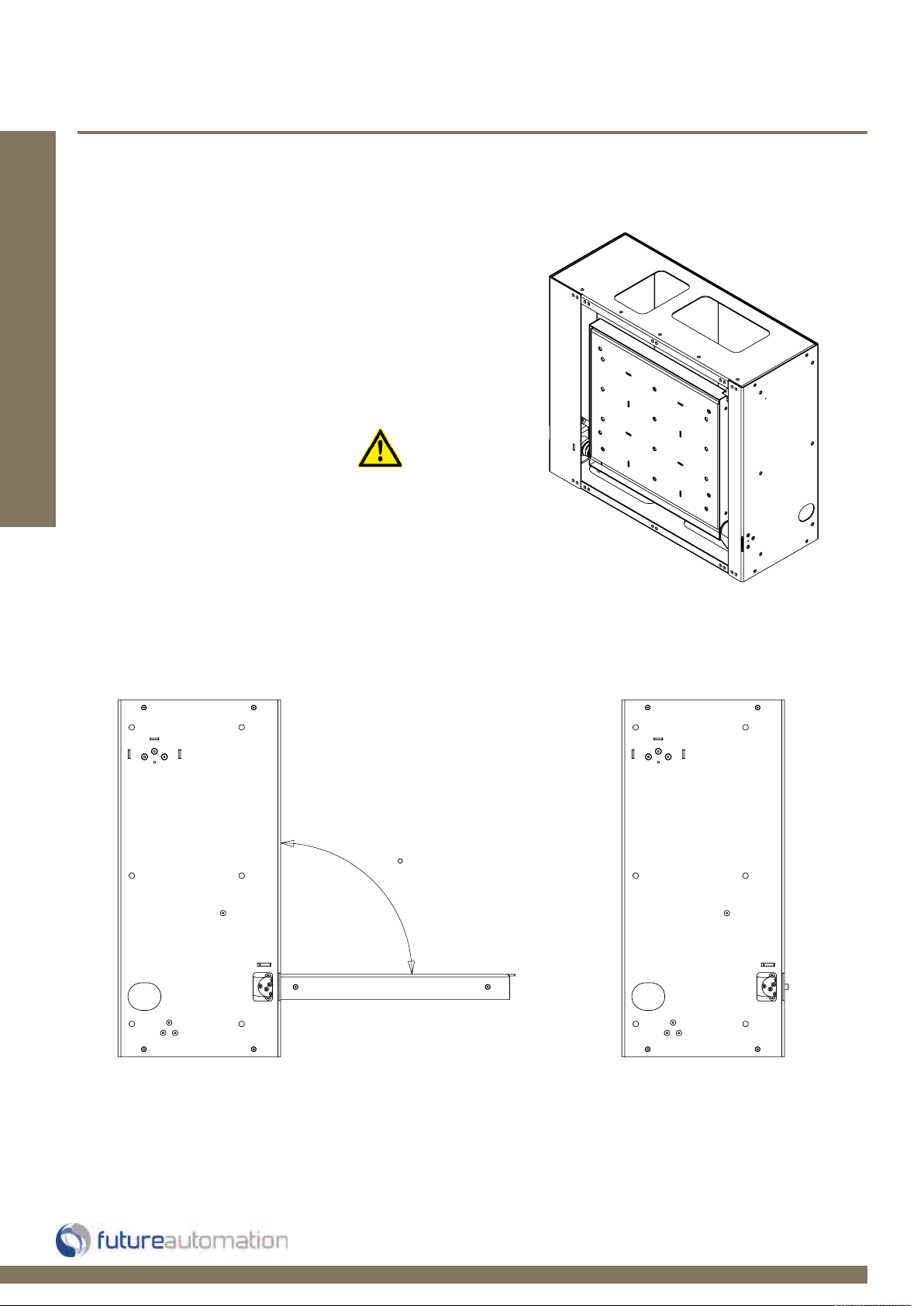
Testing
Before you start testing, check the following:
- The product is in good condition
- No damage to any parts
- Wiring is all secure
- The unit is in the closed position
Installation: Stage 1
- Test the mechanism
- See page 16 for remote operations
Test the unit when it is sitting
on the floor and is secure!
Mechanism Movement
Open Position Closed Position
90
Page 5 of 20 // email info@futureautomation.co.uk tel: +44 (0) 1438 833577 fax: +44 (0) 1438 833565
Page 7
PH2 - Projector Hinge
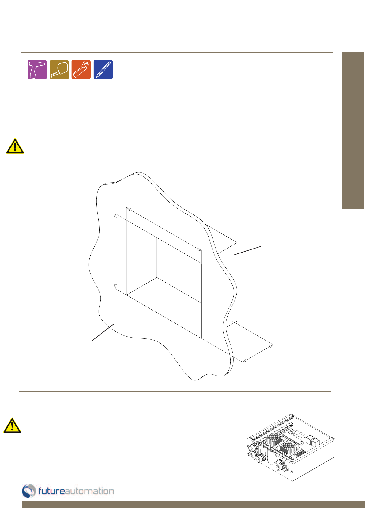
Creating the void in the wall
- Hole size for mechanism: PH2 - Width 800mm
Height 710mm
Depth 300mm
- Clear space free from joists and other objects
- Secure timber joists in place to support the unit left, right top and bottom
- ORGANISE CABLES READY TO THREAD THROUGH THE MECHANISM
800
[31.5]
Installation: Stage 2
710
[28]
Front Panel
Control box setup
- ON BOARD ELECTRONICS!
- Control box wiring, refer to page 12 Electrical Connections
- Connect the control box to the mains power supply
- Connect the infrared remote sensor even if you are going to
use switch control
- Cables can be easily extended
Back Joist
Frame Work
300 [11.8]
+ Panel
Thickness
Page 6 of 20 // email info@futureautomation.co.uk tel: +44 (0) 1438 833577 fax: +44 (0) 1438 833565
Page 8

PH2 - Projector Hinge
Installation of the mechanism into the wall
-ORGANISE THE CABLES READY TO
THREAD THROUGH THE CABLE HOLES
ON THE SIDE OF THE PRODUCT!
Installation: Stage 3
-Secure into internally out into the
joist frame work
-Check the mechanism and movement
Make sure to remove
the 2 internal covers.
Run cables for the projector and the
mechanism through joist frame work
and mechanism access holes.
Insert cassette body into
the joist frame work. Make
sure the mechanism is in
the down position so you
can get to the internal fixing
holes.
Holes for cables to
be threaded through.
Page 7 of 20 // email info@futureautomation.co.uk tel: +44 (0) 1438 833577 fax: +44 (0) 1438 833565
Page 9

PH2 - Projector Hinge
Installation: Stage 4
Cable Management & Cladding
Secure the mechanism in place
from the inside using the fixing
holes in the sides and back.
Thread cables through access
holes in the mechanism.
Cable Management Clips
Cable Access Holes
Fixing Holes
After product is secured
replace the internal covers
back into the mechanism.
Finish cladding around the
aperture parameter, either
with plaster board or MDF
strips in an existing wall.
Remember you may have to
access the mechanism for
future servicing.
Front Panel
Cladding
Page 8 of 20 // email info@futureautomation.co.uk tel: +44 (0) 1438 833577 fax: +44 (0) 1438 833565
Page 10
PH2 - Projector Hinge
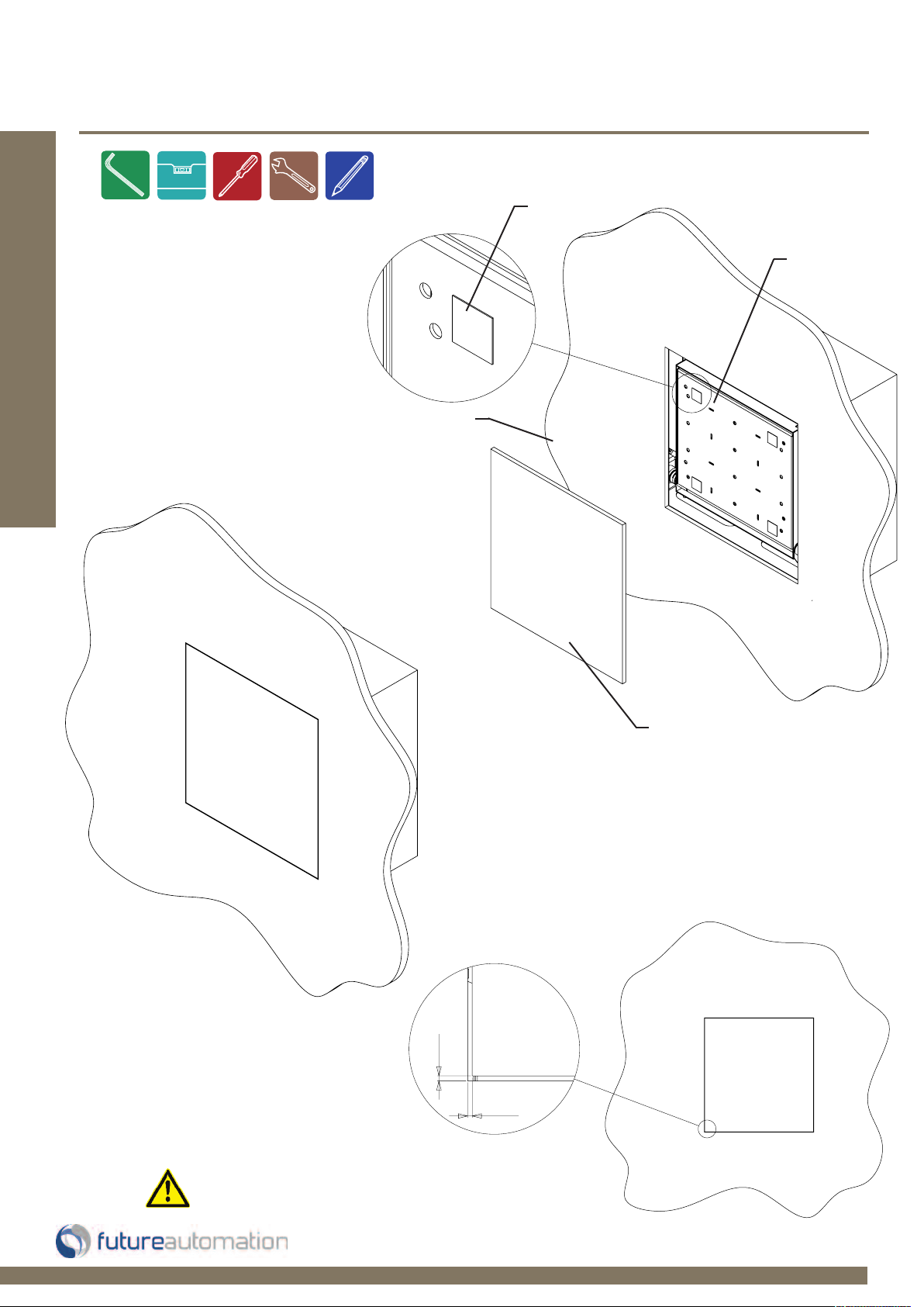
Securing The Moving Panel
Sticky Pad
Close the mechanism and
place sticky pads on the
under tray as shown. Offer
the moving panel into place
Installation: Stage 5
with a 5mm equal gap all
round. Push against sticky
pads to secure in place.
Front Panel
Under Tray
5 [0.2]
5 [0.2]
MAKE SURE MOVING PANEL HAS AN EQUAL
5mm [0.2”] GAP ALL THE WAY ROUND
Moving Panel
Page 9 of 20 // email info@futureautomation.co.uk tel: +44 (0) 1438 833577 fax: +44 (0) 1438 833565
Page 11

PH2 - Projector Hinge
Mounting Front Panel
Open the mechanism and remove
all 4 side locking bolts to release
the under tray.
Installation: Stage 6
4 x Side
Locking Bolts
Remove the under tray and
moving panel as shown and
secure together using the
appropriate fixings.
Page 10 of 20 // email info@futureautomation.co.uk tel: +44 (0) 1438 833577 fax: +44 (0) 1438 833565
Page 12

PH2 - Projector Hinge
Mounting The Projector
Mount the projector in place and connect the necessary
cables. Secure projector down from the underside using
the appropriate fixings.
Installation: Stage 7
Offer the under tray and moving
panel back up and secure back
in place using the 4 side locking
bolts.
Make sure there is enough slack in
the cables so the mechanism can
move without straining them.
Page 11 of 20 // email info@futureautomation.co.uk tel: +44 (0) 1438 833577 fax: +44 (0) 1438 833565
Final product in
the open position.
Page 13

PH2 - Projector Hinge
In & Out Position Adjustment
Turn the screws that hold the switches in place to adjust the IN and
OUT position.
Once the mechanism is installed there might be a little under or over
travel which can be sorted by adjusting these switches.
IN Switch
Installation: Switch Adjustment
OUT Switch
Page 12 of 20 // email info@futureautomation.co.uk tel: +44 (0) 1438 833577 fax: +44 (0) 1438 833565
Page 14
PH2 - Projector Hinge
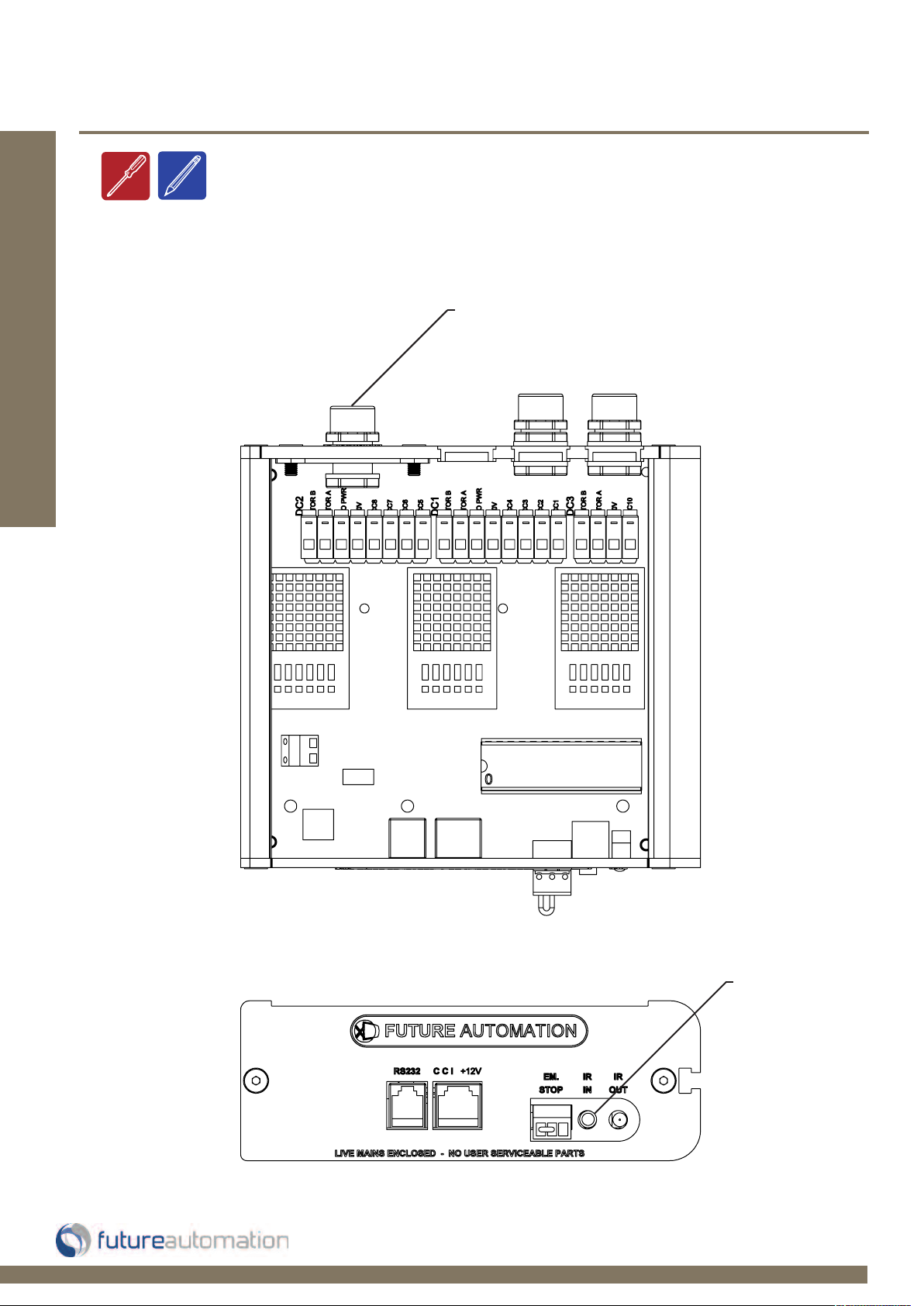
Electrical Connections & Control Box
Connect the control box to
the DC power supply and the
power supply to the mains
Installation: Electrical Connection
Page 13 of 20 // email info@futureautomation.co.uk tel: +44 (0) 1438 833577 fax: +44 (0) 1438 833565
Connect infrared
sensor here
Page 15

PH2 - Projector Hinge
SLQV
568A 568B
1 12V SUPPLY
12V SUPPLY - CURRENT LIMITED
W/G W/O
2 12V LATCH
When 12V attached, device will go OUT. When
12V removed, device will go IN.
GO
3GROUND GROUND W/OW/G
4 DEVICE LATCH
Short to GROUND (pin 3), device will go OUT,
remove short device will go IN.
BL BL N / A
5 PIN 4 NOT USED W/BL W/BL N / A
6 DEVICE STOP
Momentary short to GROUND (pin 3), stops
device in current position.
O G N / A
7 DEVICE OUT
Momentary short to GROUND (pin 3), makes
device go OUT.
W/BR W/BR N / A
8 DEVICE IN
Momentary short to GROUND (pin 3), makes
device go IN.
BR BR N / A
PIN DESCRIPTION ACTION
WIRE / CABLE
CONTACT CLOSURE
LED INDICATOR
Contact Closure
Use an RJ45 connector in the
CCI socket on the control box
to operate via contact closure
Installation: Electrical Connection
NOTE:
LED 1
LED 2
LED 3
LED 4
LED 5
Earlier versions of the control board
LED indicators.
may not have these contact closure
Page 14 of 20 // email info@futureautomation.co.uk tel: +44 (0) 1438 833577 fax: +44 (0) 1438 833565
CONTACT CLOSURE INPUT
Page 16

PH2 - Projector Hinge
SLQV
RS232
- Use an RJ25 connector in the socket marked
RS232 on the control box to operate using RS232
Details
Baud rate: 9600
Stop bit: 1
Parity: None
Databits: 8
PIN 3: GROUND TO PIN 5: GROUND
PIN 4: GROUND TO PIN 5: GROUND
Installation: RS232 and Operation Details
IMPORTANT
Ensure protocol is entered
exactly as written.
RJ25 9 PIN D
PIN 1: RX TO PIN 2: TX
PIN 6: TX TO PIN 3: RX
Protocol Action
fa_in Carriage Return (Enter ) Device IN
fa_out Carriage Return (Enter ) Device OUT
fa_stop Carriage Return (Enter ) Device STOP (At any position)
Pin 1: RX
Pin 6 : TX
Pin 3 & 4: GROUND
Page 15 of 20 // email info@futureautomation.co.uk tel: +44 (0) 1438 833577 fax: +44 (0) 1438 833565
Pin 2: TX
Pin 3: RX
Pin 5: GROUND
Page 17

PH2 - Projector Hinge
Replacing batteries
Operation: Remote Control
Future Automation IR Remote
Controller needs x2 AAA batteries
which are provided within the
packaging.
Operation Buttons
In - Raises the
mechanism
Stop - Will stop
the operation at
any point
Out - Lowers the
mechanism
Safety Note
When the mechanism is moving,
if any button is pressed apart
from those already assigned, the
mechanism will stop immediately.
Page 16 of 20 // email info@futureautomation.co.uk tel: +44 (0) 1438 833577 fax: +44 (0) 1438 833565
Page 18

PH2 - Projector Hinge
PH2 Projector Hinge Mechanism - Trouble shooting?
Trouble Shooting:
For information on our products or trouble shooting please
refer to our web site - www.futureautomation.co.uk
or for questions on installations and our product range please
phone us on - +44(0) 1438 833577 and ask for our technical
support department
Page 17 of 20 // email info@futureautomation.co.uk tel: +44 (0) 1438 833577 fax: +44 (0) 1438 833565
Page 19

PH2 - Projector Hinge
Test motor operation
If the lift is not working, you can test the motor directly. To do so, you will need to locate
and open the control box.
Trouble Shooting:
CAUTION. Apply mains voltage taking all necessary grounding precautions.
Use live (brown) and switch live (black) to change direction of motor. If the
motor works, contact manufacture to replace control box.
Page 18 of 20 // email info@futureautomation.co.uk tel: +44 (0) 1438 833577 fax: +44 (0) 1438 833565
Page 20

PH2 - Projector Hinge
PH2
Product Dimensions
(W,D,H)
800x300x710mm
[31.5x11.8x28"]
Weight (Kg) 35Kg [77.2lb]
Power Consumption 110W
Power Consumption
On Standby
3W
Lifting Capacity (Kg) 25Kg [55.1lb]
Standard Colour Black / White
Rotate Angle
90϶
Max Projector Size
(W,D,H)
460x510x190mm
[18.1x20.1x7.5"]
Control
IR Remote, RS232 &
Contact Closure
Power Supply 240V or 110V
Control Of 3rd
Party Product
Yes
Output Power Supply 12V - 240V
Control Box Size (W,D,H)
150x150x52mm
[5.9x5.9x2"]
Shipping Details
Dimensions (W,D,H)
950x400x950mm
[37.4x15.7x37.4"]
Weight (Kg) 40Kg [88.2lb]
A general technical overview of the PH2 projector hinge mechanism.
Technical overview:
Page 19 of 20 // email info@futureautomation.co.uk tel: +44 (0) 1438 833577 fax: +44 (0) 1438 833565
Page 21

PH2 - Projector Hinge
Notes...
Page 20 of 20 // email info@futureautomation.co.uk tel: +44 (0) 1438 833577 fax: +44 (0) 1438 833565
Page 22

Future Automation
Unit 2 Kimpton Enterprise Park
Claggy Road
Kimpton
Hertfordshire
SG4 8HP
United Kingdom
Tel: +44 (0) 1438 833 577
Fax: +44 (0) 1438 833 565
Email: info@futureautomation.co.uk
www.futureautomation.co.uk
 Loading...