

Page 1
MLS
Installation Instructions
Marine Lift Swivel Mechanism
ISSUE: 011
www.futureautomation.co.uk
FUTURE
AUTOMATION
Page 2
MLS
Marine Lift Swivel Mechanism
Instruction Sheet
Sheet 1 of 18
ISSUE: 011
www.futureautomation.co.uk
Your Pack
Should Contain
1 ML - S
Marine Lift
Mechanism
1 Standard ML
Fixtures Pack
The contents of
which can be
found on Sheet 18
1 IR
Remote
Control
1 Fixtures Pack
Relating to the
type of mount
your screen
requires
WARNING
It is the responsiblity of
the installer to warn all
potential end users of
the dangers of interfering
with mechanisms during
operation
IMPORTANT
Mechanisms which lift
or move weights need
to be checked on a
yearly basis for any
damage which may
result in an accident
FUTURE
AUTOMATION
Page 3

MLS
Marine Lift Swivel Mechanism
Instruction Sheet
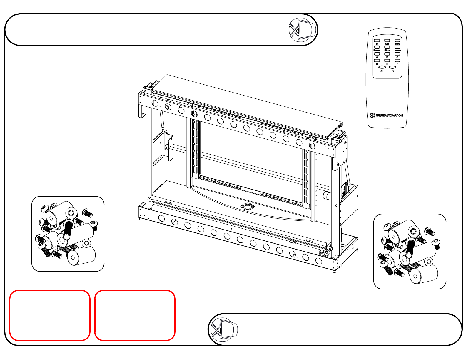
Stage 1
Check the operation of the mechanism
Firstly, remove the
cable ties that keep the
mechanism safe and
secure during transit.
There are usually 6 ties
in the locations circled
on the image, right.
However, on some models
there may be more than
6 cable ties.
Sheet 2 of 18
ISSUE: 011
www.futureautomation.co.uk
CONTROLS
Connect the mechanism and
check that the mechanism
operates correctly.
IN - HIDE SCREEN
OUT - REVEAL SCREEN
FACING FORWARD
STOP - STOP
PRESET - MEMORY
STORE + PRESET - STORE
HOME - HOME FROM
ANGLE
< - PULSE LEFT
Once all the cable ties
have been removed, then
the mechanism can be
powered up and tested.
FUTURE
> - PULSE RIGHT
Refer to page 12 for
full controls
AUTOMATION
Page 4
MLS
Marine Lift Swivel Mechanism
Instruction Sheet
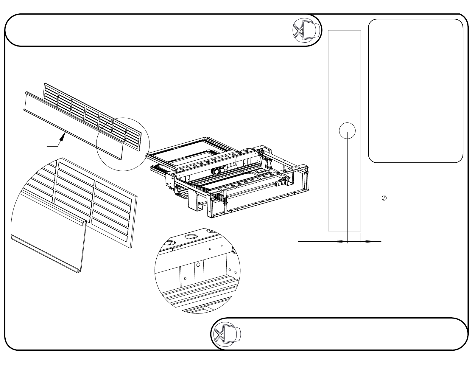
Stage 2
Fitting flap and base to mechansim
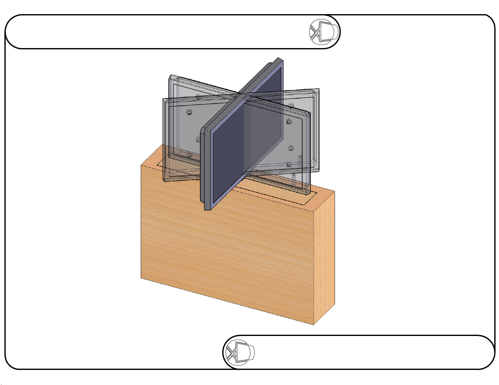
The surfaces of the flap should ideally be varnished
or painted to help prevent it from warping.
Aluminium
Flap
A
Sheet 3 of 18
ISSUE: 011
www.futureautomation.co.uk
The 6mm flap and the base should
be made as part of the cabinet.
Take care when fixing the surfaces together.
Place the objects on a flat surface to make
sure the edges are properly alligned
when they come into contact.
B
DETAIL B
SCALE 1 : 5
72.50
FIXING
Firstly, before attempting
to fix the base panel to
the mechanism, it will
be necessary to
remove the mounting
frame, for ease of
working.
Make sure the base panel
lines up squarely, directly
on top of the lifting beam.
Always consult
ML TECHNICAL SHEET
before fabricating any
flaps or base panels.
VIEWING SIDE
1 large hole to be
drilled in base panel.
This hole should be
86mm to allow for
adjustment later.
The hole's centre has
to be 72.5mm away
from the back edge
of the base panel.
DETAIL A
SCALE 1 : 5
Try to use as many self adhesive pads
as possible to get the most secure fixture.
Remove the screen mount from the mechanism and put the
base on the beam. With the base panel on the beam, it will
be possible to mark where the wood screws will need to go
through the support plates into the base panel. Mark
where the holes need to go and then drill a pilot
hole for the screws. Then screw in the
provided wood screws with washers.
FUTURE
AUTOMATION
Page 5
MLS
Marine Lift Swivel Mechanism
Instruction Sheet
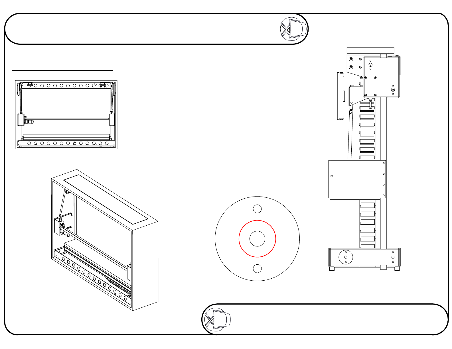
Stage 3
Fixing the lift in the cabinet
Sheet 4 of 18
ISSUE: 011
www.futureautomation.co.uk
Place the mechanism within the cabinet.
Raise the beam to the top and guide base
through the opening in the top. IR remote
STOP button will stop the lift.
With the base properly located, use the 8
pointed screws supplied, 4 on each side,
to pin the mechanism in place, fixing its
position left and right. These 8 screws
should be screwed through the middle
hole of each of the clusters of 3,
shown below right.
With the lift fixed in position, use 8 wood
screws on each side to secure the
lift to the cabinet.
DETAIL B
FUTURE
B
AUTOMATION
Page 6

MLS
Marine Lift Swivel Mechanism
Instruction Sheet
Stage 4
Adjusting the base panel height
Sheet 5 of 18
ISSUE: 011
www.futureautomation.co.uk
By adjusting the white screw
up or down, you can adjust
the stop height of the
lifting beam and so,
the base panel.
C
DETAIL C
SCALE 1 : 1.5
FUTURE
AUTOMATION
Page 7

MLS
Marine Lift Swivel Mechanism
Instruction Sheet
Stage 5
Positioning the base panel
Loosen off the wood screws on the under
side of the lifting beam and move the
base to the centre of the opening.
Sheet 6 of 18
ISSUE: 011
www.futureautomation.co.uk
MOUNTING
THE FRAME
Once the base panel has
been positioned correctly
and properly secured, it
is then possible to re-attach
the mounting frame.
Firstly make sure the
mechanism is in the
'Home' position.
There should be a gap of about 3mm
around the edges of the base panel
to the cabinet.
Then the screen mounting
frame can be bolted down.
Make sure the mounting
frame is square with the
slot in the cabinet.
D
DETAIL D
SCALE 1 : 4
FUTURE
AUTOMATION
Page 8

MLS
Instruction Sheet
Marine Lift Swivel Mechanism
Stage 6
Adjusting the flap-up position
2
3
1
Sheet 7 of 18
ISSUE: 011
www.futureautomation.co.uk
CABINET TOP - SIDE VIEW
1
By adjusting the white screw,
at each side of the lift, you can
adjust the tilt of the flap.
CABINET TOP - PLAN VIEW
2
By loosening the M6 bolts on each
side under the flap, you can adjust
the position of the flap in the hole
in the cabinet top. Aim for a
3mm gap all round.
3
By winding the push rods on each side, you can
adjust the height of the flap in order to get it level
with the cabinet top. Be sure to lock the nut securely
once adjusted. Make sure the black plate doesn't
touch the inside of the cabinet. This can cause
strain on the motor, leading to failure.
FUTURE
CABINET TOP - SIDE VIEW
AUTOMATION
Page 9

MLS
Instruction Sheet
Marine Lift Swivel Mechanism
Stage 7
Adjusting the flap-down position
Sheet 8 of 18
ISSUE: 011
www.futureautomation.co.uk
E
DETAIL E
SCALE 1 : 3
By adjusting the bolts under each flap arm, it is
possible to alter the angle the flap opens to. It is
very important that when the flap is open, it rests
4
4
FUTURE
in a vertical position, as shown above.
AUTOMATION
Page 10

MLS
Marine Lift Swivel Mechanism
Instruction Sheet
www.futureautomation.co.uk
Sheet 9 of 18
ISSUE: 011
Stage 8
Checking the screen mount
With a standard marine lift, the supplied mounting type will be either a Group A or C framework, or a VESA 200 mount.
Check that the type supplied suits the screen that is going to be mounted to the mechanism.
Group A or C Framework
Remove the uprights, hightlighted above,
and fix them to the back of the screen
using the appropriate fixings.
VESA 200 Mount
Remove the screen plate,
hightlighted above, and fix
it to the back of the screen
using the appropriate
fixings.
FUTURE
AUTOMATION
Page 11

MLS
Marine Lift Swivel Mechanism
Instruction Sheet
Stage 9
Sheet 10 of 18
ISSUE: 011
www.futureautomation.co.uk
CABLES
When the screen is in
position, the cables can be
connected and run down
into the cabinet.
Fixing the screen to the lift
Before mounting any screen, press STOP on the IR
remote in order to prevent any motor movements
during the mounting procedure.
Make sure the swivel is in the HOME position!
Simply mount the screen on to the mount supplied
with your mechanism. The example below
shows a Group A framework.
Pass the cables through
the centre of the aluminium
shaft at thye base of the
framework. Once inside the
cabinet, pass the cables
into the cable management
system. This resembles a
black chain running from
the beam to the base of the
cabinet that the cables can
be pushed inside to keep
them tidy.
The cable management
system is circled near left.
FUTURE
The height of the inner framework is
adjustable. The inner uprights will
slide inwards to allocate different
mounting systems.
AUTOMATION
Page 12

MLS
Instruction Sheet
Marine Lift Swivel Mechanism
Stage 10
Fix the IR sensor and run the mechanism
The IR sensor can be located
anywhere outside of
the cabinet.
Sheet 11 of 18
ISSUE: 011
www.futureautomation.co.uk
FUTURE
AUTOMATION
Page 13

MLS
Instruction Sheet
Marine Lift Swivel Mechanism
www.futureautomation.co.uk
Controlling The Mechanism
Viewing from the front
Sheet 12 of 18
ISSUE: 011
REMOTE
CONTROLS
IN
- Takes the screen
inside the cabinet
OUT
- Takes the screen out
of the cabinet facing forward
STOP
- Stops the mechanism
at any time
CLOSED
POSITION
PRESS
OUT
PRESS
HOME
POSITION
PRESET
learnt position
STORE
screen position to learnt
position
HOME
forward facing position when
screen is already in an angled
position
<
- Rotates screen left
>
- Rotates screen right
STORE + PRESET
sec stores preset position
STORE + E
preset and sets swivel 180
degree right and left
STORE + D
left limit
STORE + F
right limit
STORE + A-C
positions
A-C then takes it to those
positions
- Screen goes to
- Programs current
- Takes screen to
- Within 1
within 1 sec clears
within 1 sec sets
within 1 sec sets
stores other
IN
FUTURE
AUTOMATION
Page 14

MLS
Instruction Sheet
Marine Lift Swivel Mechanism
www.futureautomation.co.uk
Controlling The Mechanism
Programming new memorised positions
OUT
To rotate the
screen left or
< or >
right
Sheet 13 of 18
ISSUE: 011
POSITION OPTIONS
The example, left, shows
the programming of
a position that is
left of centre.
In order to program a
position that it right of
centre, simply press
< to turn the screen
to the right.
Then press
STORE + PRESET to
store the position
in the memory.
STORE + A-C
Also stored positions
PRESS
STORE +
PRESET
To store the
position in
the memory
30°
FUTURE
AUTOMATION
Page 15

MLS
Instruction Sheet
Marine Lift Swivel Mechanism
www.futureautomation.co.uk
Electrical Connections
The MLS mechanism must be connected to the AC1, DC1 and DC2
blocks of connections.
Remove this screw to release the lid
Connect the IEC Power Lead Here
Sheet 14 of 18
ISSUE: 011
I
DETAIL I
SCALE 2 : 2.5
Connect the Infrared Sensor here
FUTURE
It is VERY important that when all of the
electrical connections are made, the
connector blocks are connected in the
way shown above, with all the wires
coming directly out the top of the
connector blocks.
AUTOMATION
Page 16

MLS
Marine Lift Swivel Mechanism
Instruction Sheet
Contact Closure
Use an RJ45 connector in the
CC1 socket on the control box
to operate via contact closure.
Sheet 15 of 18
ISSUE: 011
www.futureautomation.co.uk
Once the mechanism is moving, any contact
1
pins
8
closure input will cause the lift to stop. There will
then be a short delay before another command
can be issued. This feature should always be
available to the end user for safety reasons.
The emergency stop connector should also be
used to connect other safety devices or switches
PIN
1
2
3
4
5
6
7
8
568
B
W/G
G
W/O
W/BL
O
W/BR
BR
568
A
W/O
O
W/G
W/BL
G
W/BR
BR
DESCRIPTION
12V SUPPLY CURRENT LIMITED
12V LATCH
GROUND
N/A
DEVICE IN LATCHED
DEVICE STOP
DEVICE OUT
DEVICE IN
ACTION
When 12V is attached, device will go OUT.
When 12V is removed, device will go IN.
Momentary short to ground to make
lift go UP and RIGHT. CC4
Momentary short to ground to make
lift go UP and LEFT. CC3
Momentary short to ground to make
lift go UP to HOME position. CC2
Momentary short to ground to make
lift go IN. CC1
FUTURE
AUTOMATION
Page 17

MLS
Marine Lift Swivel Mechanism
Instruction Sheet
RS232
Use an RJ11 connector in the
socket marked RS232 on the
control box to operate using RS232.
DETAILS
Baud rate: 9600
Stop bit: 1
Parity: None
Databits: 8
PROTOCOL
ASCI Command
fa_in = Device IN
fa_out = Device UP only
fa_stop = Device STOP
Sheet 16 of 18
ISSUE: 011
www.futureautomation.co.uk
fa_store = STORE MEMORY position
fa_preset = Go to MEMORY position
fa_home = Device UP only
fa_right = Device UP and to RIGHT limit
fa_left = Device UP and to LEFT limit
ALL COMMANDS FOLLOWED BY
CARRIAGE RUTURN
6
pins
1
PIN 1: IN
PIN 6: OUT
PIN 3&4: GROUND
6
7
8
1
2
9
3
4
5
PIN 2: IN
PIN 3: OUT
PIN 5: GROUND
FUTURE
AUTOMATION
Page 18

MLS
Marine Lift Swivel Mechanism
Instruction Sheet
Operation Details
EMERGENCY STOP
This connection will
stop all functions of
the mechanism
once broken /
removed.
Sheet 17 of 18
ISSUE: 011
www.futureautomation.co.uk
AC1
Gives an ouput of 240V(or 110V) to
control the Marine Lift motor.
Outputs stay live for 60 seconds after
the OUT or IN fuctions are selected.
DC1
A low voltage connection for the
switches in the lift mechanism. The four
LEDs indicate the state the mechanism is in.
CC1 Not Lit: Flap is OPEN
CC2 Not Lit: Flap is CLOSED
CC3 Not Lit: Beam is DOWN
CC4 Not Lit: Beam is UP
DC2
A low voltage connection for the
switches in the swivel mechanism. The two
LEDs indicate the state the mechanism is in.
FUTURE
AUTOMATION
Page 19

MLS
Marine Lift Swivel Mechanism
Instruction Sheet
Supplied Fixings
The fixings immediately below are the standard ML-S fixings supplied with every ML-S product.
There will be one other pack of fixings supplied, containing fixings that are specific
to the particular screen being mounted on the ML-S product.
Sheet 18 of 18
ISSUE: 011
www.futureautomation.co.uk
M6 x 25mm
Pointed x 8
Wood Screws x 2
Penny Washers x 2
GROUP A
M4 x 16mm x8 M5 Washers x8
M5 x 12mm x8 M6 Washers x6
M6 x 16mm x6
M8 x 16mm x6 Spacers 18 OD 8 ID 10mm x8
M8 x 25mm x4 Spacers 18 OD 8 ID 15mm x4
M8 x 30mm x4 Spacers 18 OD 8 ID 45mm x4
M8 x 50mm x4
M8 x 60mm x4
M8 x 80mm x4
VESA
M4 x 16mm x6
M4 x 20mm x6
M5 x 20mm x4
M5 x 30mm x4
M5 x 35mm x4
M6 x 20mm x4
Spacers 20 OD 6 ID 3mm x8
FUTURE
GROUP C
M4 x 16mm x4 M8 Washers x6
M5 x 16mm x4
M5 x 20mm x4 M8 Rawl Bolts x6
M5 x 30mm x4
M5 x 50mm x4 Spacers 15 OD 6 ID 15mm x4
M6 x 16mm x4 Spacers 15 OD 6 ID 30mm x4
M8 x 60mm x6 Spacers 20 OD 6 ID 3mm x4
AUTOMATION
 Loading...