

Page 1
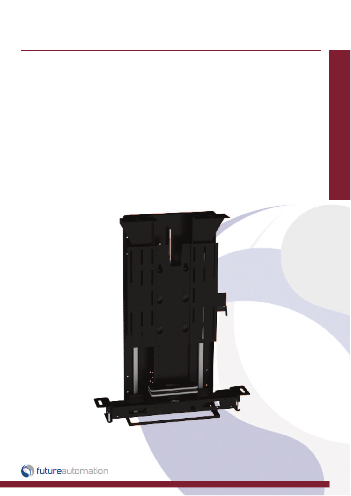
Installation Instructions
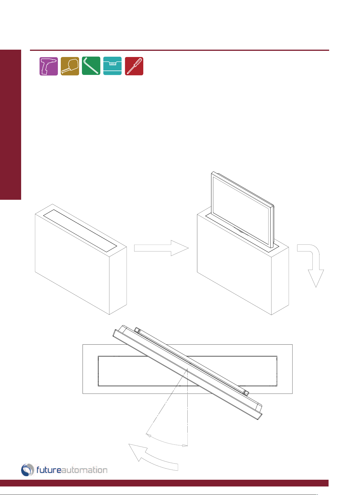
LSM S BE - Lift System Medium
Swivel Box Enclosure
Design Highlights
-Quiet Smooth Lifting Action at Approximately 40mm [1.6”] per Second
-180 Degrees of Quiet, Fast Screen Rotation in Both Directions With
Programmable Viewing Positions
-Full Cable Management
-Wide Range of Mounting Options
-24V DC Motor. Suitable for Direct DC Supply
-Marine Suitable Robust Beam
Lift Mechanisms
Thank you for choosing
futureautomation
email info@futureautomation.co.uk tel: +44 (0) 1438 833577 fax: +44 (0) 1438 833565 ISSUE 002
Page 2
LSM S BE - Lift System Medium Swivel Box Enclosure
Safety Disclaimer
Important Safety Instructions
Explanation of graphical symbols
-(Electric Shock Symbol) = The lightning flash within an equilateral triangle is intended to alert you to the presence of un-insulated
“dangerous voltage” within the products enclosure that may be of sufficient magnitude to constitute an electric shock to persons
-(Caution Symbol) = The exclamation point within an equilateral triangle is intended to alert you to the presence of important
operating and maintenance (servicing) instructions in the literature accompanying the product
-(Tools Symbols) = The tools symbol within a coloured square are intended to highlight the required tools necessary for correct and
safe installation of the product. These are intended as a
guide only, and it is at the installer’s discretion as to which tools are used.
WARNING: RISK OF ELECTRIC SHOCK, ONLY AUTHORIZED INSTALLERS TO OPEN THE POWER CONTROL BOX.
WARNING: To reduce the risk of fire or electric shock, do not expose electrical parts to rain or moisture, unless the
product has been specifically designed to do so.
Introduction: Safety Information
WARNING: Failure to provide adequate structural strengthening, prior to installation can result in serious personal injury or damage to the
equipment. It is the installer’s responsibility to ensure the structure to which the component is affixed can support the four times the
weight of the component.
WARNING: Do not exceed the weight capacity. This can result in serious personal injury or damage to the equipment. It is the installer’s
responsibility to ensure that the total combined weight of all attached components does not exceed that of the maximum figure stated.
WARNING: Failure to provide adequate structural strength for this component can result in serious personal injury or damage to equipment! It is the installer’s responsibility to make sure the structure to which this component is attached can support five times the combined
weight of all equipment. Reinforce the structure as required before installing the component.
Warnings:
1. Read all technical instructions fully before installation and use. It is the installer’s responsibility to ensure that all
documentation is passed on the end user and read fully before operation.
2. Keep all documentation.
3. Heed all warnings.
4. Follow all technical specifications and instructions during installation.
5. Do not use near water unless the product has been specifically designed to do so.
6. Clean only with a dry cloth.
7. Do not defeat the purpose of the polarized or grounding type plug. A polarized plug has two blades, one wider
than the other. A grounding type plug has two blades and a grounding prong. The wide blade or third prong are
provided for your safety. If the provided plug does not fit your outlet, consult an electrician or contact the
manufacturer.
8. Protect the power cord from being walked on or pinched, particularly at plugs, convenience receptacles, and the
point where the exit from the apparatus.
9. Unplug the apparatus during lightning storms or when unused for long periods of time.
10. Only use attachments/accessories specified by the manufacturer.
11. Refer all servicing to qualified personnel. Servicing is required regularly on an annual basis, when the apparatus is
damaged in any way, liquid has been spilled or objects have fallen into the apparatus, the apparatus has been
exposed to rain or moisture, does not operate normally, or has been dropped.
12. To completely disconnect the apparatus form the AC mains, disconnect the power cord plug from the AC
receptacle on the power control box.
13. To prevent overheating, do not cover the apparatus. Install in accordance with the instructions.
14. UK, Ireland and Hong Kong only – The power cord is supplied with a 13A plug having an earthing pin. The
apparatus is earthed and this pin is not required for safety, merely to operate the safety shutter of mains outlet.
15. No naked flames such as lit candles should be placed on the unit.
16. Observe and follow the local regulations when disposing of batteries.
17. Do not expose the unit to dripping or splashing fluids.
18. Do not place objects filled with liquid, such as vases, on the unit.
19. Do not expose the batteries to excessive heat such as sunshine, fire or the like.
20. For all mounted apparatus, the apparatus should be installed on solid wood, bricks, concrete or solid wood
columns and battens.
21. Always turn off power at source before putting on or taking off parts and cleaning.
22. Do not use outdoors unless marked for outdoor use.
23. Exceeding the weight capacity can result in serious personal injury or damage to equipment.
Caution
Warning
Beware of
Moving Parts
Danger
Electricity
Keep Hands
Clear
Future Sound & Vision trading as Future Automation intend to make this and all documentation as accurate as possible. However, Future
Automation makes no claim that the information contained herein covers all details, conditions or variations, nor does it provide for every
possible contingency in connection with the installation or use of this product. The information contained in this document is subject to
change without prior notice or obligation of any kind. Future Automation makes no representation of warranty, expressed or implied,
regarding the information contained herein. Future Automation assumes no responsibility for accuracy, completeness or sufficiency of the
information contained in this document.
Page 1 of 20 // email info@futureautomation.co.uk tel: +44 (0) 1438 833577 fax: +44 (0) 1438 833565
Page 3

LSM S BE - Lift System Medium Swivel Box Enclosure
Contents Page
Introduction
Safety Information 1
Contents 2
Contents 3
Tool Indicator Icons 3
Installation
Parts List
Package Contents 4
Stage 1
Before You Start 5
Remove KH Screen Mount 5
Stage 2
Fixing the Lift in the Cabinet 6
Stage 3
KH Upright Assembly 7
Stage 4
Mounting the Base Panel 8
Stage 5
KH Upright Mounting 9
Stage 6
Attaching the Box Enclosure 10
Stage 7
Screen Plate & Box Enclosure Mounting 11
Stage 8
Screen & Box Enclosure Mounting 12
Stage 9
Switch Adjustment 13
Stage 10
Controlling the Mechanism 14
Stage 11
Controlling the Mechanism 15
Electrical Connections
Contact Closure 16
RS232 Control 17
IR Controls 18
Introduction: Contents
Page 2 of 20 // email info@futureautomation.co.uk tel: +44 (0) 1438 833577 fax: +44 (0) 1438 833565
Page 4

LSM S BE - Lift System Medium Swivel Box Enclosure
Contents Page
Operations
RF Control & Operation 17
Storing Positions 18
Changing Batteries 18
Notes 19
Technical Overview 19
Trouble Shooting 20
Introduction: Contents / Tool Indicator
Tool Indicator Icons
1. 2. 3. 4. 5. 6.
7.
8.
1. - Drill 3. - Allen Keys 5. - Screwdrivers 7. - Pencil
2. - Tape measure 4. - Spirit Level 6. - Spanners 8. - Saw
This product carries a warranty that covers the cost of labour and spare parts incurred by any defects in materials and workmanship under normal use
during a two year period from date of purchase. Support for any problems that are not hardware faults are excluded from the warranty entitlement.
This warranty does not affect your statutory consumer rights.
The following is excluded from warranty service:
• Malfunctioning caused by misuse or damage, accidental or otherwise, or service modification by persons not authorised by Future Automation,
or the use of any non Future Automation supplied parts;
• Any electrical, or other environmental work external to your Future Automation mechanism including power cuts, surges or lightning strikes;
• Additional items not supplied by Future Automation although they may have been supplied together by the retailer;
• Any 3rd party software products controlling your mechanism;
• Any transfer of ownership. Warranty is provided only to the initial purchaser;
• Compensation for loss of use of the product, and consequential loss of any kind;
• Use of the product over the specified weight capacity;
• Any damage to products during transit that is not checked and notified as “unchecked” or “damaged” upon receipt of delivery.
Product Warranty
Any part of your system that needs to be replaced during a warranty repair becomes the property of Future Automation.
Page 3 of 20 // email info@futureautomation.co.uk tel: +44 (0) 1438 833577 fax: +44 (0) 1438 833565
Page 5
LSM S BE - Lift System Medium Swivel Box Enclosure
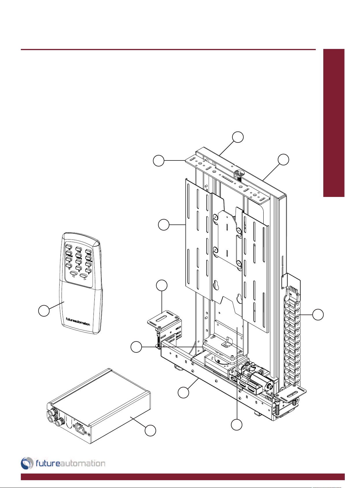
Package Contents
1 - Mechanism
1.1 - Back Plate
1.2 - Lifting Beam
1.3 - Base Panel Brackets
1.4 - KH Mount Upright
1.5 - Screen Mount
1.6 - Cable Management
1.7 - Lid Mount Bracket
1.8 - Box Enclosure Base
2 - Control Box
3 - Remote Control
Not Shown On Page
4 - x2 AAA Batteries
5 - Multi Pack Of Nuts,
Bolts & Washers
6 - Mains Power & Other
Leads
Nuts & Bolts Multipack:
A range of nuts, bolts, washers
and spacers to help add in the
mounting for your screen
1.7
1.5
Installation: Parts List
1
1.1
1.3
3
1.8
1.2
1.4
2
1.6
Page 4 of 20 // email info@futureautomation.co.uk tel: +44 (0) 1438 833577 fax: +44 (0) 1438 833565
Page 6

LSM S BE - Lift System Medium Swivel Box Enclosure
Before You Start
Check the Operation of the Mechanism.
Firstly, remove all the red cable ties which keep the mechanism safe and secure during
transit. Once they have all been removed, the mechanism can be powered up and tested.
Installation: Stage 1
Connect the supplied IR remote and check that the mechanism operates correctly before
continuing with the installation.
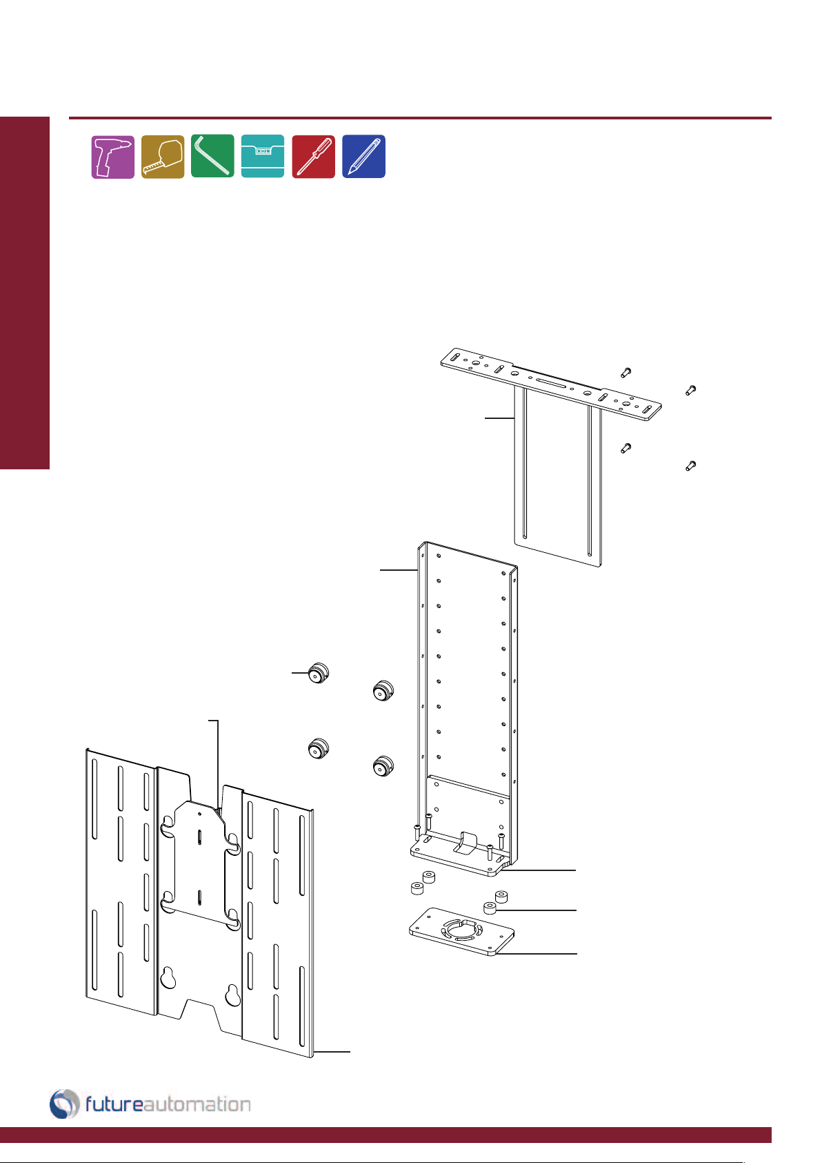
Remove KH Screen Mount
Take the KH mount off the mechanism by removing the upright from the BOX ENCLOSURE
BASE held by the 4 button head screws. In-between these parts are 4 TRANSPORT
SPACERS which can be discarded.
KH MOUNT
UPRIGHT
TRANSPORT
SPACER
LID MOUNT BRACKET
SCREEN MOUNT
BOX ENCLOSURE BASE
Page 5 of 20 // email info@futureautomation.co.uk tel: +44 (0) 1438 833577 fax: +44 (0) 1438 833565
Page 7
LSM S BE - Lift System Medium Swivel Box Enclosure
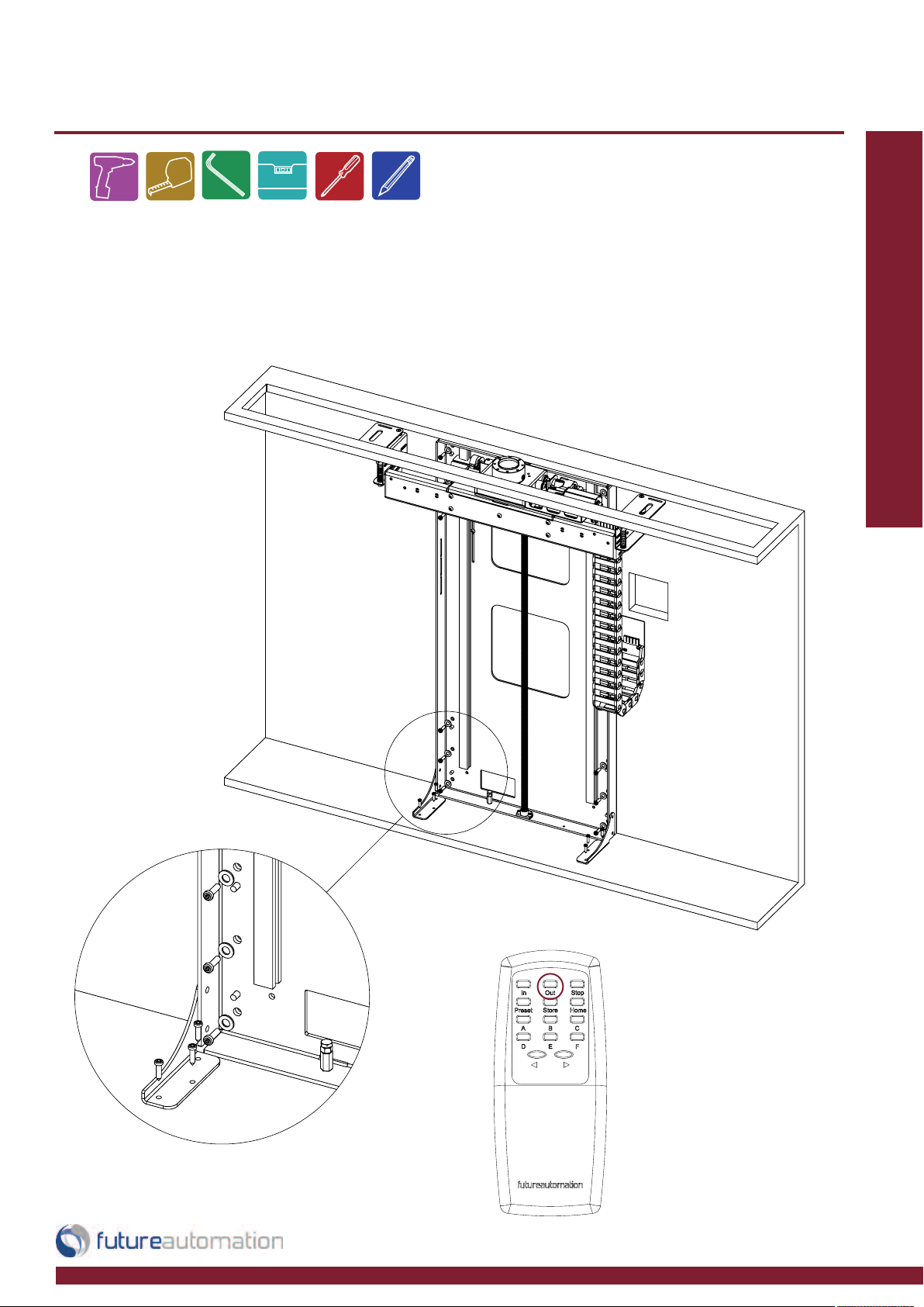
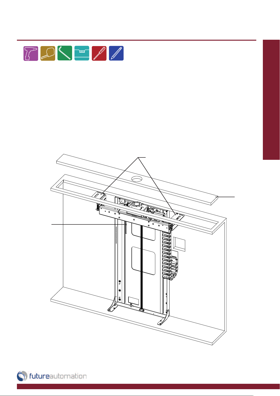
Fixing the Lift in the Cabinet
Place the mechanism centrally within the cabinet. Raise and lower the lifting
beam as required to fix the lift where shown in all corners.
Installation: Stage 2
Page 6 of 20 // email info@futureautomation.co.uk tel: +44 (0) 1438 833577 fax: +44 (0) 1438 833565
Page 8
LSM S BE - Lift System Medium Swivel Box Enclosure
KH Upright Assembly
Below shows the KH UPRIGHT assembly. To release the SCREEN MOUNT PLATE rotate
the top LOCKING LEVER and lift off the TOGGLES. The TOGGLES can adjust the height by
moving up or down the KH UPRIGHT, these TOGGLE fixings also secure the LID MOUNT
Installation: Stage 3
BRACKET which can slide up and down to fit box enclosure cabinetry.
LID MOUNT BRACKET
LOCKING LEVER
KH UPRIGHT
TOGGLES
UPRIGHT FOOT PLATE
TRANSPORT SPACERS
BOX ENCLOSURE
BASE PLATE
SCREEN MOUNT PLATE
Page 7 of 20 // email info@futureautomation.co.uk tel: +44 (0) 1438 833577 fax: +44 (0) 1438 833565
Page 9
LSM S BE - Lift System Medium Swivel Box Enclosure
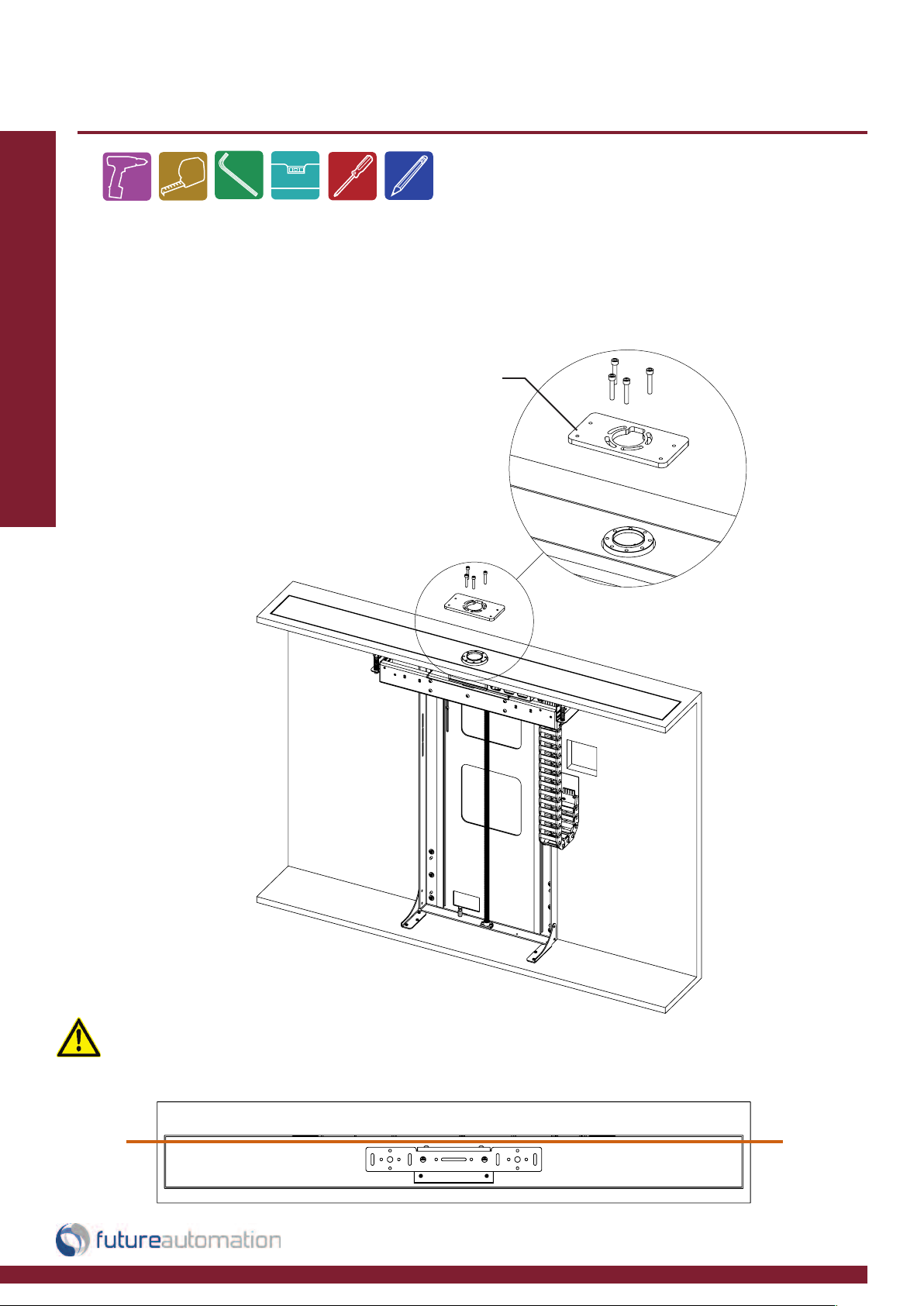
Mounting the Base Panel
After the mechanism is in the correct position the next step is to lower the BASE PANEL
into place and fix from the underside through the BASE PANEL BRACKETS. A good tip
is to place the BASE PANEL in place and draw marks from the underside through the
BASE PANEL BRACKETS, then fix using a wood screw and a large penny washer, this
will allow you to adjust the position.
BASE PANEL BRACKETS
Installation: Stage 4
You can adjust
the OUT position
by loosening
these screws and
sliding the switch
plate up or down
BASE
PANEL
Page 8 of 20 // email info@futureautomation.co.uk tel: +44 (0) 1438 833577 fax: +44 (0) 1438 833565
Page 10
LSM S BE - Lift System Medium Swivel Box Enclosure
KH Upright Mounting
Fix the BOX ENCLOSURE MOUNT PLATE to the mechanism as shown to the right. Use
as many cap head bolts as possible, some of the tapped holes might not be accessible.
Installation: Stage 5
BOX ENCLOSURE
MOUNT PLATE
Make sure when you re-mount the KH MOUNT
UPRIGHT its square to the cabinet opening.
Page 9 of 20 // email info@futureautomation.co.uk tel: +44 (0) 1438 833577 fax: +44 (0) 1438 833565
Page 11

LSM S BE - Lift System Medium Swivel Box Enclosure
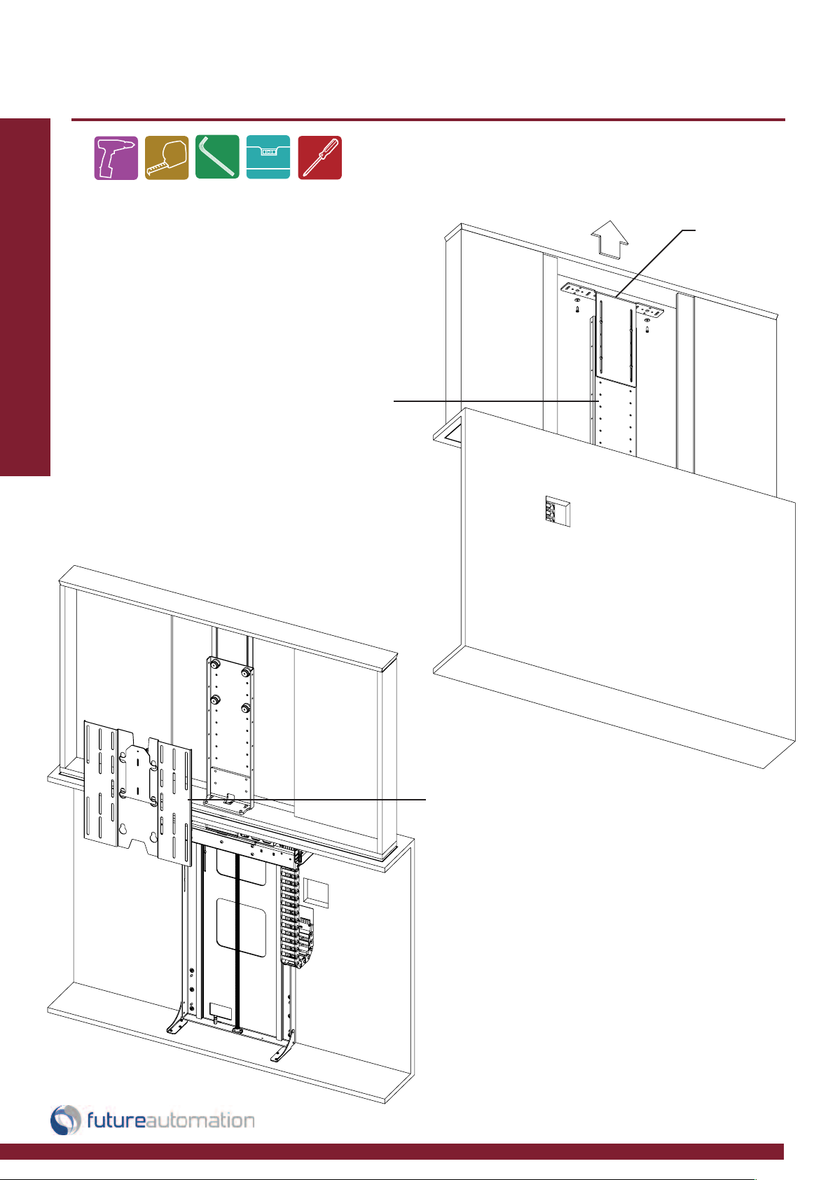
KH Upright Mounting & Cable Routing
With the screen plate removed,
attach the KH MOUNT UPRIGHT
back on to the mechanism the
same way it was removed. Thread
the screen and power cables
through the cable management
chain and then through the lifting
beam shown with the dotted line.
KH MOUNT
UPRIGHT
Installation: Stage 6
7mm
[0.3”]
8mm
[0.3”]
Page 10 of 20 // email info@futureautomation.co.uk tel: +44 (0) 1438 833577 fax: +44 (0) 1438 833565
Page 12
LSM S BE - Lift System Medium Swivel Box Enclosure
Screen Plate & Box Enclosure Mounting
Secure the BOX ENCLOSURE to the
UPRIGHT by sliding the LID MOUNT
BRACKET up and fixing to the enclosure
top as shown.
Installation: Stage 7
KH MOUNT
UPRIGHT
LID MOUNT
BRACKET
SCREEN MOUNT
PLATE
Page 11 of 20 // email info@futureautomation.co.uk tel: +44 (0) 1438 833577 fax: +44 (0) 1438 833565
Hook the SCREEN MOUNT PLATE
on to the KH UPRIGHT over the
TOGGLES and secure using the
LOCKING LEVER.
Page 13

LSM S BE - Lift System Medium Swivel Box Enclosure
Screen & Box Enclosure Mounting
Slide the screen into the
enclosure and fix to the
SCREEN MOUNT PLATE.
A good tip is to use a
packer under the screen
and remove once fixed.
Installation: Stage 8
Finally offer the box enclosure back panel
and fix to the sides. This back panel needs
to be removable to take the screen off.
Page 12 of 20 // email info@futureautomation.co.uk tel: +44 (0) 1438 833577 fax: +44 (0) 1438 833565
Page 14

LSM S BE - Lift System Medium Swivel Box Enclosure
Switch Adjustments
You can adjust the IN and OUT position of the lifting beam. Detail 1 shows how
to adjust the OUT position and detail 2 shows how to adjust the IN position.
The IR sensor can be located anywhere outside of the cabinet.
Installation: Stage 9
1 - The top switch can’t be adjusted
when the mechanism is in the OUT
position, because the switch is active.
Lower the mechanism and press
STOP about 100mm [4”] and then
adjust the OUT switch plate.
1
2 - Height of the lower
post determines the
IN position
2
Page 13 of 20 // email info@futureautomation.co.uk tel: +44 (0) 1438 833577 fax: +44 (0) 1438 833565
Page 15

LSM S BE - Lift System Medium Swivel Box Enclosure
Controlling the Mechanism
Installation: Stage 10
IN - Takes the screen inside the cabinet
OUT - Takes the screen out of the cabinet
facing forward
STOP - Stops the mechanism at any time
PRESET - Screen goes to learnt position
STORE - Programs current screen position
to learnt position
HOME - Takes screen to forward facing
position when screen is already in an
angled position
< - Rotates screen left
> - Rotates screen right
STORE + PRESET - Within 1 sec stores
preset position
STORE + E - within 1 sec clears right &
left limit and allows the swivel to rotate
180 degree right and left
STORE + D - within 1 sec sets left limit
STORE + F - within 1 sec sets right limit
STORE + A-C - stores other positions
A-C then takes it to those positions
CLOSED
POSITION
PRESS
OUT
OPEN
POSITION
PRESS
IN
Page 14 of 20 // email info@futureautomation.co.uk tel: +44 (0) 1438 833577 fax: +44 (0) 1438 833565
Page 16
LSM S BE - Lift System Medium Swivel Box Enclosure
Controlling the Mechanism
Programming new memorised positions.
The example, shows the programming of a position that is left of centre.
Installation: Stage 11
In order to program a position that it right of centre, simply press > to turn
the screen to the right.
Then press STORE + PRESET to store the position in the memory.
STORE + A-C Also stored positions
OUT
< or >
To rotate
the screen
left or right
Press
STORE + PRESET
To store the position
in the memory
Page 15 of 20 // email info@futureautomation.co.uk tel: +44 (0) 1438 833577 fax: +44 (0) 1438 833565
Page 14 of 20 // email info@futureautomation.co.uk tel: +44 (0) 1438 833577 fax: +44 (0) 1438 833565
Page 17

SLQV
568A 568B
1 12V SUPPLY 12V SUPPLY - CURRENT LIMITED W/G W/O
2 PIN 2 NOT USED G O
3GROUND GROUND W/OW/G
4 PIN 4 NOT USED BL BL
5 DEVICE LEFT
Momentary short to GROUND (pin 3), will
make device go LEFT.
W/BL W/BL LED 4
6 DEVICE RIGHT
Momentary short to GROUND (pin 3), will
make device go RIGHT.
O G LED 3
7 DEVICE HOME
Momentary short to GROUND (pin 3),
makes device go OUT / HOME.
W/BR W/BR LED 2
8 DEVICE IN
Momentary short to GROUND (pin 3),
makes device go IN.
BR BR LED 1
PIN DESCRIPTION ACTION
WIRE / CABLE
CONTACT CLOSURE
LED INDICATOR
LSM S BE - Lift System Medium Swivel Box Enclosure
Contact Closure
- Use an RJ45 connector in the CCI
socket on the control box to operate
via contact closure
Installation: Contact Closure
LED 1
LED 2
Any contact closure input whilst
the mechanism is in motion will
LED 3
LED 4
LED 5
stop the movement and all other
contact closure commands will
be disabled for 1 second.
Page 16 of 20 // email info@futureautomation.co.uk tel: +44 (0) 1438 833577 fax: +44 (0) 1438 833565
CONTACT CLOSURE
INPUT
Page 18

S
LQV
LSM S BE - Lift System Medium Swivel Box Enclosure
RS232
- Use an RJ25 connector
in the socket marked
RS232 on the control box
to operate using RS232
Pin 1: RX
Installation: RS232 Control
Pin 6 : TX
Pin 3 & 4: GROUND
Pin 2: TX
Pin 3: RX
Pin 5: GROUND
Details
RJ25 9 PIN D
Baud rate: 9600
Stop bit: 1
Parity: None
Databits: 8
PIN 1: RX TO PIN 2: TX
PIN 6: TX TO PIN 3: RX
PIN 3: GROUND TO PIN 5: GROUND
PIN 4: GROUND TO PIN 5: GROUND
IMPORTANT
Ensure protocol is entered exactly as written, including Carriage Return (Enter / ASCII 13).
PROTOCOL ACTION
fa_in Carriage Return (Enter ) Device IN
fa_out Carriage Return (Enter ) Beam OUT no movement to swivel
fa_right Carriage Return (Enter ) Device OUT RIGHT limit
fa_left Carriage Return (Enter ) Device OUT LEFT limit
fa_preset Carriage Return (Enter ) Device to PRESET memory position
fa_a Carriage Return (Enter ) Device OUT to memory position a
fa_b Carriage Return (Enter ) Device OUT to memory position b
fa_c Carriage Return (Enter ) Device OUT to memory position c
fa_stop Carriage Return (Enter ) STOPS the device at any position
fa_home Carriage Return (Enter ) Device OUT swivel parallel
Connection Locations
Page 17 of 20 // email info@futureautomation.co.uk tel: +44 (0) 1438 833577 fax: +44 (0) 1438 833565
Emergency Stop Connector
RS232
Contact Closure
Mains Voltage Input
IR LED
IR Input Jack
Page 19

LSM S BE - Lift System Medium Swivel Box Enclosure
Operation buttons for the IR remote
Installation: IR Control
In - Brings the mechanism
into the cabinet
Preset - Screen goes
to learnt position
Store - Programs current
screen position to learnt
position
Out - Brings the
mechanism out of the
cabinet facing forward
Stop - Will stop the
operation at any position
Note
Only buttons indicated are
functional with the product.
Any button pressed when in
motion mechanism will stop.
Home - Takes screen to forward
facing position when screen is
already in an angled position
< - Rotates Screen left
> - Rotates Screen right
Store + Preset - Within 1
sec stores preset position
Store + E - Within 1 sec
clears preset and sets swivel
180 degree right and left
Store + D - Within 1 sec
sets left limit
Store + F - Within 1 sec
sets right limit
Store + A-C - Stores
other positions A-C then
takes it to those positions
Replacing batteries
Future Automation IR
Remote Controller
needs x2 AAA batteries
which are provided
within the packaging
Page 18 of 20 // email info@futureautomation.co.uk tel: +44 (0) 1438 833577 fax: +44 (0) 1438 833565
Page 20

LSM S BE - Lift System Medium Swivel Box Enclosure
Lift System Medium Swivel Box Enclosure - Trouble shooting guide
Lift System Medium Swivel Box Enclosure - Trouble shooting
Trouble Shooting:
For information on our products please refer to our web site -
www.futureautomation.co.uk
or for questions on installations and our product range please
phone us on - +44(0) 1438 833577 and ask for our technical
support department
Notes...
Page 19 of 20 // email info@futureautomation.co.uk tel: +44 (0) 1438 833577 fax: +44 (0) 1438 833565
Page 21

LSM S BE - Lift System Medium Swivel Box Enclosure
Product Size Range LSM S BE 3 LSM S BE 4 LSM S BE 5 LSM S BE 6 LSM S BE 7
Width - 745mm [29.3"] Width - 745mm [29.3"] Width - 745mm [29.3"] Width - 745mm [29.3"] Width - 745mm [29.3"]
Height - 769mm [32.3"] Height - 820mm [32.3"] Height - 880mm [34.6"] Height - 950mm [37.4"] Height - 1060mm [41.7"]
Depth - 165mm [6.5] Depth - 165mm [6.5] Depth - 165mm [6.5] Depth - 165mm [6.5] Depth - 165mm [6.5]
Weight Approx
25Kg [55.1lb] 25Kg [55.1lb] 25Kg [55.1lb] 25Kg [55.1lb] 25Kg [55.1lb]
Power Consumption
250W - 500W 250W - 500W 250W - 500W 250W - 500W 250W - 500W
Power Consumption
On Standby
100mA 100mA 100mA 100mA 100mA
Lifting Capacity
50Kg [110lb] 50Kg [110lb] 50Kg [110lb] 50Kg [110lb] 50Kg [110lb]
Lifting Capacity Marine
30Kg [66lb] 30Kg [66lb] 30Kg [66lb] 30Kg [66lb] 30Kg [66lb]
Standard Screen Mount
Colour
Black Black Black Black Black
Max Television Size
Width - 564mm [26.6"] Height - 675mm [26.6"] Height - 735mm [28.9"] Height - 805mm [31.7"] Height - 915mm [36"]
Control
IR Remote, RF Remote,
Contact Closure & RS232
IR Remote, RF Remote,
Contact Closure & RS232
IR Remote, RF Remote,
Contact Closure & RS232
IR Remote, RF Remote,
Contact Closure & RS232
IR Remote, RF Remote,
Contact Closure & RS232
Power Supply
240V or 110V 240V or 110V 240V or 110V 240V or 110V 240V or 110V
Control Of 3rd Party Product
Yes Yes Yes Yes Yes
Output Power Supply
Yes (12V) Yes (12V) Yes (12V) Yes (12V) Yes (12V)
Control Box Size (W,D,H)
150x210x52mm
[5.9x8.3x2.0"]
150x210x52mm
[5.9x8.3x2.0"]
150x210x52mm
[5.9x8.3x2.0"]
150x210x52mm
[5.9x8.3x2.0"]
150x210x52mm
[5.9x8.3x2.0"]
Shipping Details
Dimensions Approx (W,D,H)
Weight Approx
30Kg [66.1lb] 30Kg [66.1lb] 30Kg [66.1lb] 30Kg [66.1lb] 30Kg [66.1lb]
Product Dimensions
1800x500x1200mm
[70.9x19.7x47.2"]
1800x500x1200mm
[70.9x19.7x47.2"]
1800x500x1200mm
[70.9x19.7x47.2"]
1800x500x1200mm
[70.9x19.7x47.2"]
1800x500x1200mm
[70.9x19.7x47.2"]
LSM S BE RANGE
Technical Overview
A general technical overview of the LSM S BE lift mechanism range
Technical Overview:
Page 20 of 20 // email info@futureautomation.co.uk tel: +44 (0) 1438 833577 fax: +44 (0) 1438 833565
Page 22

Future Automation
Unit 2 Kimpton Enterprise Park
Claggy Road
Kimpton
Hertfordshire
SG4 8HP
United Kingdom
Tel: +44 (0) 1438 833 577
Fax: +44 (0) 1438 833 565
Email: info@futureautomation.co.uk
www.futureautomation.co.uk
 Loading...