

Installation Instructions
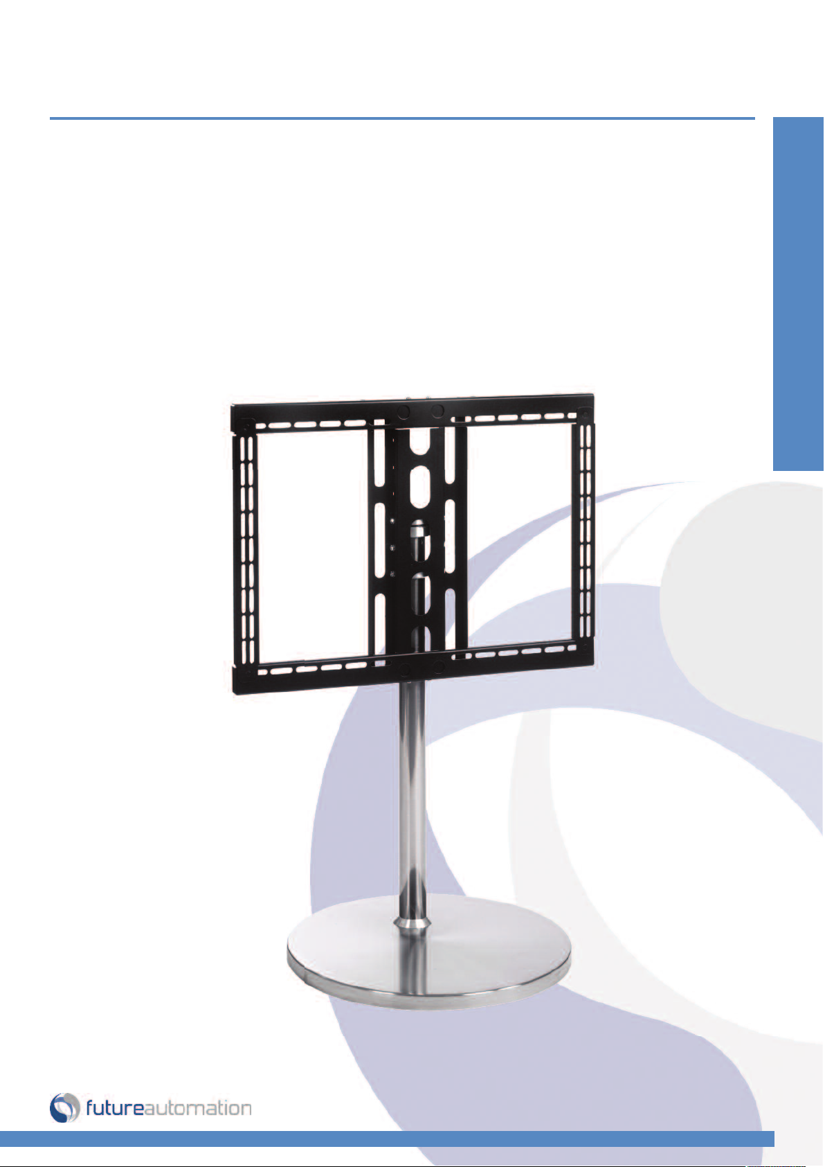
FM - Floor Mount
Design Highlights
-Fully concealed cable management
-Stainless steel finish
-Bi-Directional swivel
-Vesa 400 X 680 adjustable frame
-Smooth manual movement
Floor & Table Top Mounts
Thank you for choosing
futureautomation
email info@futureautomation.co.uk tel: +44 (0) 1438 833577 fax: +44 (0) 1438 833565 ISSUE 001
FM - Floor Mount
Safety Disclaimer
Important Safety Instructions
Explanation of graphical symbols
-(Electric Shock Symbol) = The lightning flash within an equilateral triangle is intended to alert you to the presence of un-insulated
“dangerous voltage” within the products enclosure that may be of sufficient magnitude to constitute an electric shock to persons
-(Caution Symbol) = The exclamation point within an equilateral triangle is intended to alert you to the presence of important
operating and maintenance (servicing) instructions in the literature accompanying the product
-(Tools Symbols) = The tools symbol within a coloured square are intended to highlight the required tools necessary for correct and
safe installation of the product. These are intended as a
guide only, and it is at the installer’s discretion as to which tools are used.
WARNING: RISK OF ELECTRIC SHOCK, ONLY AUTHORIZED INSTALLERS TO OPEN THE POWER CONTROL BOX.
WARNING: To reduce the risk of fire or electric shock, do not expose electrical parts to rain or moisture, unless the
product has been specifically designed to do so.
Introduction: Safety Information
WARNING: Failure to provide adequate structural strengthening, prior to installation can result in serious personal injury or damage to the
equipment. It is the installer’s responsibility to ensure the structure to which the component is affixed can support the four times the
weight of the component.
WARNING: Do not exceed the weight capacity. This can result in serious personal injury or damage to the equipment. It is the installer’s
responsibility to ensure that the total combined weight of all attached components does not exceed that of the maximum figure stated.
WARNING: Failure to provide adequate structural strength for this component can result in serious personal injury or damage to equipment! It is the installer’s responsibility to make sure the structure to which this component is attached can support five times the combined
weight of all equipment. Reinforce the structure as required before installing the component.
Warnings:
1. Read all technical instructions fully before installation and use. It is the installer’s responsibility to ensure that all
documentation is passed on the end user and read fully before operation.
2. Keep all documentation.
3. Heed all warnings.
4. Follow all technical specifications and instructions during installation.
5. Do not use near water unless the product has been specifically designed to do so.
6. Clean only with a dry cloth.
7. Do not defeat the purpose of the polarized or grounding type plug. A polarized plug has two blades, one wider
than the other. A grounding type plug has two blades and a grounding prong. The wide blade or third prong are
provided for your safety. If the provided plug does not fit your outlet, consult an electrician or contact the
manufacturer.
8. Protect the power cord from being walked on or pinched, particularly at plugs, convenience receptacles, and the
point where the exit from the apparatus.
9. Unplug the apparatus during lightning storms or when unused for long periods of time.
10. Only use attachments/accessories specified by the manufacturer.
11. Refer all servicing to qualified personnel. Servicing is required regularly on an annual basis, when the apparatus is
damaged in any way, liquid has been spilled or objects have fallen into the apparatus, the apparatus has been
exposed to rain or moisture, does not operate normally, or has been dropped.
12. To completely disconnect the apparatus form the AC mains, disconnect the power cord plug from the AC
receptacle on the power control box.
13. To prevent overheating, do not cover the apparatus. Install in accordance with the instructions.
14. UK, Ireland and Hong Kong only – The power cord is supplied with a 13A plug having an earthing pin. The
apparatus is earthed and this pin is not required for safety, merely to operate the safety shutter of mains outlet.
15. No naked flames such as lit candles should be placed on the unit.
16. Observe and follow the local regulations when disposing of batteries.
17. Do not expose the unit to dripping or splashing fluids.
18. Do not place objects filled with liquid, such as vases, on the unit.
19. Do not expose the batteries to excessive heat such as sunshine, fire or the like.
20. For all mounted apparatus, the apparatus should be installed on solid wood, bricks, concrete or solid wood
columns and battens.
21. Always turn off power at source before putting on or taking off parts and cleaning.
22. Do not use outdoors unless marked for outdoor use.
23. Exceeding the weight capacity can result in serious personal injury or damage to equipment.
Caution
Warning
Beware of
Moving Parts
Danger
Electricity
Keep Hands
Clear
Future Sound & Vision trading as Future Automation intend to make this and all documentation as accurate as possible. However, Future
Automation makes no claim that the information contained herein covers all details, conditions or variations, nor does it provide for every
possible contingency in connection with the installation or use of this product. The information contained in this document is subject to
change without prior notice or obligation of any kind. Future Automation makes no representation of warranty, expressed or implied,
regarding the information contained herein. Future Automation assumes no responsibility for accuracy, completeness or sufficiency of the
information contained in this document.
Page 1 of 10 // email info@futureautomation.co.uk tel: +44 (0) 1438 833577 fax: +44 (0) 1438 833565

FM - Floor Mount
Contents Page
Introduction
Safety Information 1
Contents 2
Contents 3
Tool Indicator Icons 3
Installation
Parts List
Package Contents 4
Stage 1
Fixing the Pole to the Base 5
Stage 2
Fixing the Collars & Washer 6
Stage 3
Fixing the Frame Brackets 7
Stage 4
Attaching the Screen Mount 8
Stage 5
Assembling the Uprights 9
Stage 6
Mounting the Screen & Cable Management 10
Introduction: Contents
Page 2 of 10 // email info@futureautomation.co.uk tel: +44 (0) 1438 833577 fax: +44 (0) 1438 833565

FM - Floor Mount
Introduction: Contents / Tool Indicator
Tool Indicator Icons
1. 2. 3. 4. 5. 6.
1. - Drill 3. - Allen Keys 5. - Screwdrivers 7. - Pencil
2. - Tape measure 4. - Spirit Level 6. - Spanners 8. - Saw
Page 3 of 10 // email info@futureautomation.co.uk tel: +44 (0) 1438 833577 fax: +44 (0) 1438 833565
7.
8.

FM - Floor Mount
Package Contents
1 - Screen Mount
2 - Base
3 - Base cover
4 - Stainless Steel Pole
5 - Frame Bracket
6 - Collars and Washers
7 - Base Collar
Not Shown On Page
7 - Multi Pack Of Nuts,
Bolts & Washers:
Installation: Package Contents
1
7
3
6
2
4
5
Page 4 of 10 // email info@futureautomation.co.uk tel: +44 (0) 1438 833577 fax: +44 (0) 1438 833565

FM - Floor Mount
Fixing The Pole To The Base
Check the product is in good condition and there’s no damage to any parts. Make sure the
Base is the right way round with the feet on the floor, line the pole into place and fix using
the fixings provided. Make sure the orientation of the pole is the right way with the holes at
Installation: Stage 1
the top end.
Drop the Base Cover and Base Collar over the
pole and slide down to the base.
Page 5 of 10 // email info@futureautomation.co.uk tel: +44 (0) 1438 833577 fax: +44 (0) 1438 833565

FM - Floor Mount
Installation: Stage 2
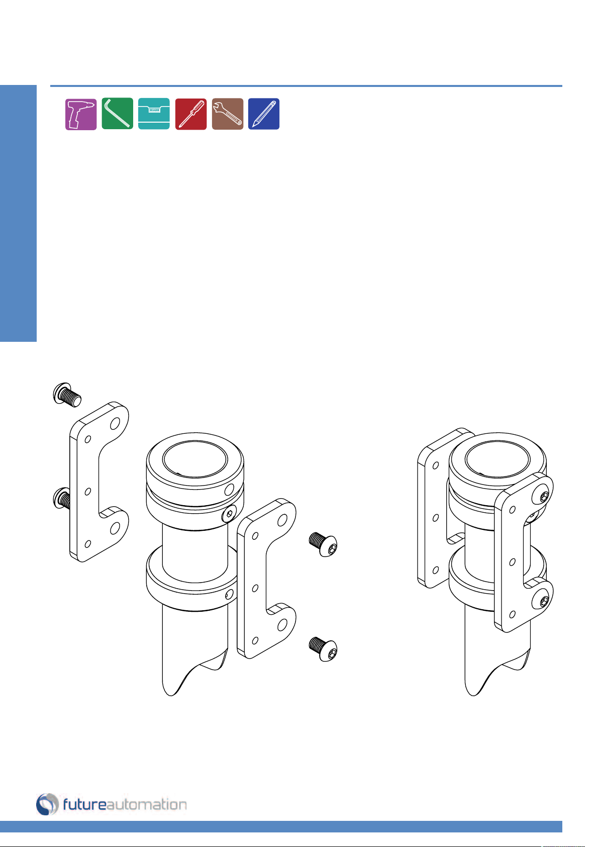
Fixing The Collars and Washer
Arrange the Collars and Washer into the
correct order as shown to the right.
Slide onto the pole and fix through the
Middle Collar using 2 M8 nuts inside the
pole and 2 M8X25mm CKS bolts
through the Middle Collar.
The Washer and Top Collar can sit on
the fixed Middle Collar, but the Bottom
Collar will be loose at this point.
TOP COLLAR
WASHER
MIDDLE COLLAR
BOTTOM COLLAR
Page 6 of 11 // email info@futureautomation.co.uk tel: +44 (0) 1438 833577 fax: +44 (0) 1438 833565
FM - Floor Mount
Fixing The Frame Brackets
Fix the Frame Brackets to the Top and Bottom Collar as shown below.
Fix the Frame Brackets to the Top Collar first then you can slide the Bottom Collar
up the pole and align with the lower mount holes.
Use 4 M10X16mm Button Head bolts which are provided with the product.
Installation: Stage 3
Page 7 of 11 // email info@futureautomation.co.uk tel: +44 (0) 1438 833577 fax: +44 (0) 1438 833565

FM - Floor Mount
Attaching The Screen Mount
First decide what height you want to fix the Screen Mount by using the
multiple height fixing holes. Use 4 M6 Nuts and 4 M6X20mm Button
Head bolts to secure onto the Frame Brackets.
Installation: Stage 4
Page 8 of 11 // email info@futureautomation.co.uk tel: +44 (0) 1438 833577 fax: +44 (0) 1438 833565
FM - Floor Mount
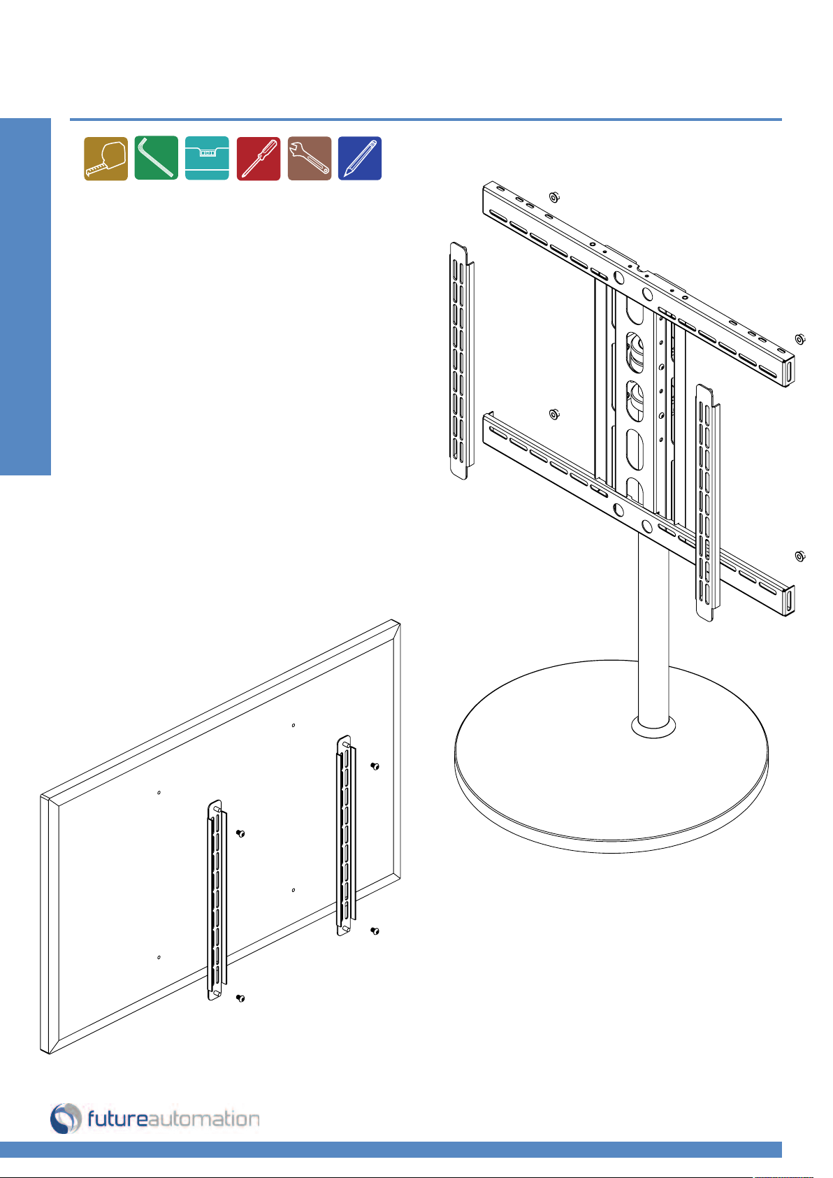
Assembling The Uprights
Remove the Uprights from the Frame
Mount by removing the 4 M6 nuts shown
on the right.
Fix the Uprights to the rear of the screen, a
variety of bolts will be provided with the
product.
Installation: Stage 5
Page 9 of 11 // email info@futureautomation.co.uk tel: +44 (0) 1438 833577 fax: +44 (0) 1438 833565

FM - Floor Mount
Mounting The Screen &
Cable Management
Mount the screen and Uprights
back onto the Frame Mount
using the M6 nuts removed in the
previous stage.
Finally connect all the cables to
the screen and run down through
the pole and out at the rear of the
Base Mount.
Installation: Stage 6
Page 10 of 11 // email info@futureautomation.co.uk tel: +44 (0) 1438 833577 fax: +44 (0) 1438 833565

Future Automation
Unit 2 Kimpton Enterprise Park
Claggy Road
Kimpton
Hertfordshire
SG4 8HP
United Kingdom
Tel: +44 (0) 1438 833 577
Fax: +44 (0) 1438 833 565
Email: info@futureautomation.co.uk
www.futureautomation.co.uk
 Loading...