

It is the responsibility of
the installer to warn all
potential end users of
the dangers of interfering
with mechanisms during
operation
WARNING
IMPORTANT
Mechanisms which lift
or move weights need
to be checked on a
yearly basis for any
damage which may
result in an accident
www.futureautomation.co.uk tel: +44 (0) 1438 833 577 fax: +44 (0) 1438 833 565
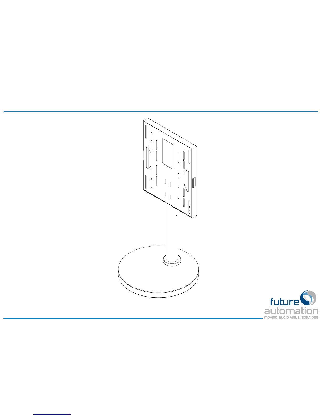
FME - Floor Mount Electric
Installation Guide
ISSUE 001
SHEET 1 of 7

SCREEN MOUNT PLATE
BASE TOP
BOTTOM COVER FLANGE
TRANSPORT BRACKET
UPPER PLATE
BASE PLATE
SCREEN MOUNT COVER
CENTRE TUBE
IR RECEIVER
BASE SUB-ASSEMBLY
MOUNT SUB-ASSEMBLY
Package Contents
Each FME will be shipped in two subassemblies; mount and base, along with
all necessary fixings and cables.
Before installing the mechanism ensure
that the instructions are read carefully and
that all parts and wiring are undamaged
and secure.
www.futureautomation.co.uk tel: +44 (0) 1438 833 577 fax: +44 (0) 1438 833 565
FME - Floor Mount Electric
Installation Guide
ISSUE 001
SHEET 2 of 7
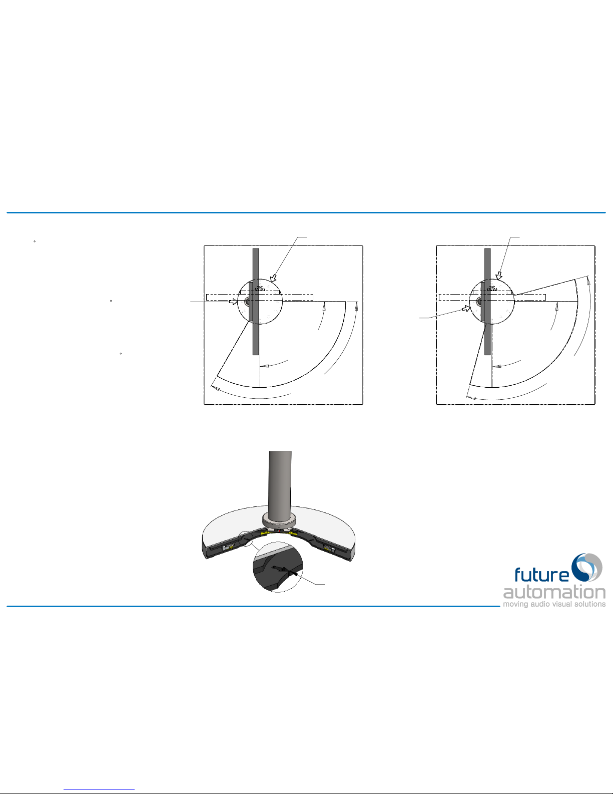
90°
Install Sweep
120°
Max Sweep
RIGHT
Limit Switch
LEFT
Limit Switch
CORRECT INSTALLATION
The installation sweep angle shares an end point
with the maximum sweep angle, allowing the
RIGHT limit switch to be seen.
90°
Install Sweep
120°
Max Sweep
RIGHT
Limit Switch
LEFT
Limit Switch
INCORRECT INSTALLATION
The installation sweep angle works within the
maximum sweep angle so neither limit switch can
be seen during normal operation.
Cut-outs in base plate identify
limit switch positions
Mechanism Positioning
The FME enables a screen to be rotated
up to 60
in both directions from center.
Software allows intermediate positions to
be learnt and selected using the IR
remote.
! IMPORTANT !
In installations where the full 120
of
travel is not required or possible it is
important that the RIGHT end switche can
be seen to ensure accurate and
consistent positioning of the mechanism.
If there are obstructions that prevent the
mechanism being able to rotate 120
the
RIGHT limit switch must be positioned
within the installation sweep angle.
A new LEFT limit position can be set
using the IR remote (see Page 4).
Arrow cut-outs in the base plate show
each limit switch position, these should be
used when positioning the mechanism.
www.futureautomation.co.uk tel: +44 (0) 1438 833 577 fax: +44 (0) 1438 833 565
FME - Floor Mount Electric
Installation Guide
ISSUE 001
SHEET 3 of 7

LEFT
A
B
C D
E
F
RIGHT
PRESET
Mechanism Control
PRESET POSITIONS
Preset positions become active once the
mechanism has travelled fully LEFT and fully
RIGHT or a maximum LEFT limit is set.
To adjust presets press STOP in the desired
position then STORE and you’ll have a 2 sec
window to press PRESET or buttons A-F to
save that position to that particular button.
If the power is cut while the mechanism is
moving its position will need to be rereferenced (see Mechanism Reset).
Until referenced, the mechanism will not be
able to access stored positions and will only
be able to move right in short pulses.
MECHANISM RESET
If the mechanism does not see one of the limit
switches for a long period of time its position
counting may lose accuracy.
To re-reference the position counting simply
send the mechanism to the RIGHT position.
If the full 120
sweep is not being used the
mechanism must be able to be sent to the
RIGHT limit (see Page 3 for details).
SETTING LEFT LIMIT
If the full 120
travel cannot be used because
of physical obstructions the LEFT limit can be
programmed by stopping the mechanism at
the desired position and pressing STORE then
LEFT.
This limit can be cleared by pressing STORE
then STOP then LEFT.
If the LEFT limit is set by the installer the
preset positions will be equally spaced
between this new travel sweep.
www.futureautomation.co.uk tel: +44 (0) 1438 833 577 fax: +44 (0) 1438 833 565
FME - Floor Mount Electric
Installation Guide
ISSUE 001
SHEET 4 of 7

1.
Remove Base Top from Base sub-assembly.
3.
Mount the Center Tube to the Base Top Plate using
4 x M6x12 bolts supplied.
Note:
The tube must be orientated so that the IR
receiver is facing in the direction shown.
4.
Remove the red Transport Bracket from the base.
! IMPORTANT !
This must be removed before operating the
mechanism.
Installation
2.
Remove 4 x M4 bolts from Center Tube and lift off
screen mount.
www.futureautomation.co.uk tel: +44 (0) 1438 833 577 fax: +44 (0) 1438 833 565
FME - Floor Mount Electric
Installation Guide
ISSUE 001
SHEET 5 of 7

SCREEN MOUNT COVER
SCREEN MOUNT PLATE
SCREEN
6.
Remove Cover from Screen Mount by releasing 4 x
M6 CSK bolts.
7.
Fix screen to Screen Mount using appropriate fixings.
Note:
Spacers may be required if the screen
mounting holes are recessed or if the back of the
screen is not flat.
5.
Run screen cables up Center Tube.
Screen and power cables can terminate in the center
of the mechanism or run out underneath to another
location.
SIDE ELEVATION
8.
Slide Base Top and Bottom Cover over Center Tube
before remounting Screen Mount (screen not shown)
Installation
www.futureautomation.co.uk tel: +44 (0) 1438 833 577 fax: +44 (0) 1438 833 565
FME - Floor Mount Electric
Installation Guide
ISSUE 001
SHEET 6 of 7

12 0.5
TYP
10.
Return mechanism to its central position, rotate base
top as shown and fix to the floor through 4 x
12mm
fixing holes.
11.
Make any adjustments to the vertical position of the
TV and remount Back Cover.
Installation
9.
Power mechanism to the RIGHT position and
position the base so that all criteria mentioned on
Page 3
are satisfied.
www.futureautomation.co.uk tel: +44 (0) 1438 833 577 fax: +44 (0) 1438 833 565
FME - Floor Mount Electric
Installation Guide
ISSUE 001
SHEET 7 of 7
 Loading...