


Installation Instructions
ET / ET60 - Electric Tilt Mechanism
Design Highlights
-Downward Tilt Up To 20 Degrees
-Smooth Quiet Motion
-Onboard Electronics
Wall Mounts
Thank you for choosing
futureautomation
email info@futureautomation.co.uk tel: +44 (0) 1438 833577 fax: +44 (0) 1438 833565 ISSUE 001

ET / ET60 - Electric Tilt Mechanism
Safety Disclaimer
Important Safety Instructions
Explanation of graphical symbols
-(Electric Shock Symbol) = The lightning flash within an equilateral triangle is intended to alert you to the presence of un-insulated
“dangerous voltage” within the products enclosure that may be of sufficient magnitude to constitute an electric shock to persons
-(Caution Symbol) = The exclamation point within an equilateral triangle is intended to alert you to the presence of important
operating and maintenance (servicing) instructions in the literature accompanying the product
-(Tools Symbols) = The tools symbol within a coloured square are intended to highlight the required tools necessary for correct and
safe installation of the product. These are intended as a
guide only, and it is at the installer’s discretion as to which tools are used.
WARNING: RISK OF ELECTRIC SHOCK, ONLY AUTHORIZED INSTALLERS TO OPEN THE POWER CONTROL BOX.
WARNING: To reduce the risk of fire or electric shock, do not expose electrical parts to rain or moisture, unless the
product has been specifically designed to do so.
Introduction: Safety disclaimer
WARNING: Failure to provide adequate structural strengthening, prior to installation can result in serious personal injury or damage to the
equipment. It is the installer’s responsibility to ensure the structure to which the component is affixed can support the four times the
weight of the component.
WARNING: Do not exceed the weight capacity. This can result in serious personal injury or damage to the equipment. It is the installer’s
responsibility to ensure that the total combined weight of all attached components does not exceed that of the maximum figure stated.
WARNING: Failure to provide adequate structural strength for this component can result in serious personal injury or damage to equipment! It is the installer’s responsibility to make sure the structure to which this component is attached can support five times the combined
weight of all equipment. Reinforce the structure as required before installing the component.
Warnings:
1. Read all technical instructions fully before installation and use. It is the installer’s responsibility to ensure that all
documentation is passed on the end user and read fully before operation.
2. Keep all documentation.
3. Heed all warnings.
4. Follow all technical specifications and instructions during installation.
5. Do not use near water unless the product has been specifically designed to do so.
6. Clean only with a dry cloth.
7. Do not defeat the purpose of the polarized or grounding type plug. A polarized plug has two blades, one wider
than the other. A grounding type plug has two blades and a grounding prong. The wide blade or third prong are
provided for your safety. If the provided plug does not fit your outlet, consult an electrician or contact the
manufacturer.
8. Protect the power cord from being walked on or pinched, particularly at plugs, convenience receptacles, and the
point where the exit from the apparatus.
9. Unplug the apparatus during lightning storms or when unused for long periods of time.
10. Only use attachments/accessories specified by the manufacturer.
11. Refer all servicing to qualified personnel. Servicing is required regularly on an annual basis, when the apparatus is
damaged in any way, liquid has been spilled or objects have fallen into the apparatus, the apparatus has been
exposed to rain or moisture, does not operate normally, or has been dropped.
12. To completely disconnect the apparatus form the AC mains, disconnect the power cord plug from the AC
receptacle on the power control box.
13. To prevent overheating, do not cover the apparatus. Install in accordance with the instructions.
14. UK, Ireland and Hong Kong only – The power cord is supplied with a 13A plug having an earthing pin. The
apparatus is earthed and this pin is not required for safety, merely to operate the safety shutter of mains outlet.
15. No naked flames such as lit candles should be placed on the unit.
16. Observe and follow the local regulations when disposing of batteries.
17. Do not expose the unit to dripping or splashing fluids.
18. Do not place objects filled with liquid, such as vases, on the unit.
19. Do not expose the batteries to excessive heat such as sunshine, fire or the like.
20. For all mounted apparatus, the apparatus should be installed on solid wood, bricks, concrete or solid wood
columns and battens.
21. Always turn off power at source before putting on or taking off parts and cleaning.
22. Do not use outdoors unless marked for outdoor use.
23. Exceeding the weight capacity can result in serious personal injury or damage to equipment.
Caution
Warning
Beware of
Moving Parts
Danger
Electricity
Keep Hands
Clear
Future Sound & Vision trading as Future Automation intend to make this and all documentation as accurate as possible. However, Future
Automation makes no claim that the information contained herein covers all details, conditions or variations, nor does it provide for every
possible contingency in connection with the installation or use of this product. The information contained in this document is subject to
change without prior notice or obligation of any kind. Future Automation makes no representation of warranty, expressed or implied,
regarding the information contained herein. Future Automation assumes no responsibility for accuracy, completeness or sufficiency of the
information contained in this document.
Page 1 of 18 // email info@futureautomation.co.uk tel: +44 (0) 1438 833577 fax: +44 (0) 1438 833565

ET / ET60 - Electric Tilt Mechanism
Contents Page
Introduction
Safety Disclaimer 1
Warning Icons 1
Contents 2
Contents 2
Tool Indicator Icons 3
Installation
Package Contents
Before You Start Check 4
Stage 1
Decide On The Mechanism Position 5
Positioning The First Hole In The Wall 5
Stage 2
Fixing To The Wall 6
Stage 3
Removing The Uprights 7
Stage 4
Fitting The Uprights To The Screen 8
Stage 5
Fitting The Screen To The Mechanism 9
Stage 6
Adjusting The Out Position 10
Electrical Connections
Electrical Connections In The Control Box 11
Contact Closure 12
Warning Lights 12
RS232
Wiring & Control Box Detail 13
Introduction: Contents
Operation
Operation Details 14
Remote Control 15
Trouble Shooting 15/16
Technical Overview 16
Product Warranty and Notes 17
Page 2 of 18 // email info@futureautomation.co.uk tel: +44 (0) 1438 833577 fax: +44 (0) 1438 833565

ET / ET60 - Electric Tilt Mechanism
Contents Page
Installation: Package Contents
Tool Indicator Icons
1. 2. 3. 4. 5. 6.
1. - Drill 3. - Allen Keys 5. - Screwdrivers 7. - Pencil
2. - Tape measure 4. - Spirit Level 6. - Spanners 8. - Saw
Page 3 of 18 // email info@futureautomation.co.uk tel: +44 (0) 1438 833577 fax: +44 (0) 1438 833565
7.
8.

ET / ET60 - Electric Tilt Mechanism
Installation: Stage 1
Before you start, check the following:
- The product is in good condition
- No damage to any parts
- Wiring is all secure
- The unit is in the closed position
Package Contents
1 - Mechanism
1.1 - Wall Mount Plate
1.2 - Control Box
1.3 - Strap
1.4 - Motor Tube
1.5 - Screen Uprights
2 - IR Remote
Not Shown On Page
3 - Multi pack of nuts and bolts
1.4
1.3
ET Mechanism
The only difference between
the ET & ET60 is the length
of the uprights as shown.
ET60 Mechanism
1.5
2
1.1
1.2
1.5
1
Important
Make sure to test that the
mechanism is working correctly.
Page 4 of 18 // email info@futureautomation.co.uk tel: +44 (0) 1438 833577 fax: +44 (0) 1438 833565

ET / ET60 - Electric Tilt Mechanism
Decide on the mechanism position
Before the mechanism can be fitted, it is important to decide on it’s exact position relative to
the screen. Place the screen face down on the floor and lay the mechanism on the back.
Measure from the top of the screen to a fixing hole so you can work out the positioning on
Installation: Stage 2
the wall.
Make sure that the screen is within 140mm from the bottom of the mechanism so it doesn't
foul on the wall when in the out position. For further details and dimensions please refer to
the technical sheets.
Mount offset
140mm MAX
Remember to account for any horizontal
off set on the screen mounting holes.
Page 5 of 18 // email info@futureautomation.co.uk tel: +44 (0) 1438 833577 fax: +44 (0) 1438 833565

ET / ET60 - Electric Tilt Mechanism
Fixing to the wall
After you have measured the screen positioning on the wall mark where the first fixing will go.
With the bracket hanging by the one fixing, make sure that the bracket is square and level by
using a spirit level. Once square, mark the other holes and fix accordingly.
Installation: Stage 3
Always use appropriate fixing types. Suitability of wall fixings will depend on the type of wall
the product is to be fixed to. If unsure, please seek instruction from your supply dealer.
Page 6 of 18 // email info@futureautomation.co.uk tel: +44 (0) 1438 833577 fax: +44 (0) 1438 833565

ET / ET60 - Electric Tilt Mechanism
Removing the uprights
Firstly remove the aluminium retaining collars. This will allow
the uprights to unhook off the mechanism, to then be fitted to
the rear of the screen.
Installation: Stage 4
Page 7 of 18 // email info@futureautomation.co.uk tel: +44 (0) 1438 833577 fax: +44 (0) 1438 833565
Retaining
collar X 4

ET / ET60 - Electric Tilt Mechanism
Fitting the uprights to the screen
Bolt the uprights to the back of the screen
using the appropriate fixings as shown below.
Installation: Stage 5
Page 8 of 18 // email info@futureautomation.co.uk tel: +44 (0) 1438 833577 fax: +44 (0) 1438 833565

ET / ET60 - Electric Tilt Mechanism
Fitting the screen to the mechanism
Hook the uprights back over the horizontal bars on the mechanism.
Installation: Stage 6
It is important that the aluminium retainers, which were removed in the earlier stage,
are replaced so that the screen can not be knocked off the bracket accidently.
Tighten the grub screws in the retainers so that the screen cannot slide left or right.
Page 9 of 18 // email info@futureautomation.co.uk tel: +44 (0) 1438 833577 fax: +44 (0) 1438 833565

ET / ET60 - Electric Tilt Mechanism
Adjusting the Out Position
Below in the detailed view you can see the motor control adjustment switches, using a
thin flat head screwdriver you can adjust the switches to alter the IN & OUT position.
Adjuster 1, adjusts the IN position.
Adjuster 2, adjusts the OUT position.
IN Position
Installation: Stage 7
Rotate anticlockwise to
stop higher
OUT Position
Rotate anticlockwise to
stop lower
Rotate
clockwise to
stop lower
Rotate
clockwise to
stop higher
Page 10 of 18 // email info@futureautomation.co.uk tel: +44 (0) 1438 833577 fax: +44 (0) 1438 833565
ET / ET60 - Electric Tilt Mechanism
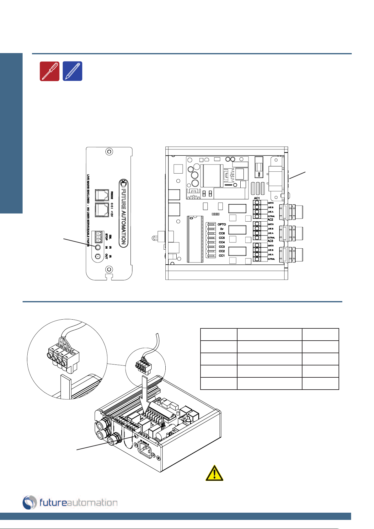
Connections
- The mechanism must be connected to the AC1.
Connect IEC
Installation: Electrical Connection
power lead here
Connect infrared
sensor here
240v AC2 Connection 110v
Earth Green
Brown Live B Black
Black Live A Red
Blue Neutral White
Remove this screw
to release the lid
Page 11 of 18 // email info@futureautomation.co.uk tel: +44 (0) 1438 833577 fax: +44 (0) 1438 833565
Ensure the plug is connected
correctly and secure

ET / ET60 - Electric Tilt Mechanism
S
LQV
568A 568B
1 12V SUPPLY
12V SUPPLY - CURRENT LIMITED
W/G W/O
2 12V LATCH
When 12V attached, device will go OUT. When
12V removed, device will go IN.
GO
3GROUND GROUND W/OW/G
4 PIN 4 NOT USED BL BL
5 DEVICE LATCH
Short to GROUND (pin 3), device will go OUT,
remove short device will go IN.
W/BL W/BL LED 4
6 DEVICE STOP
Momentary short to GROUND (pin 3), stops
device in current position.
O G LED 3
7 DEVICE OUT
Momentary short to GROUND (pin 3), makes
device go OUT.
W/BR W/BR LED 2
8 DEVICE IN
Momentary short to GROUND (pin 3), makes
device go IN.
BR BR LED 1
PIN DESCRIPTION ACTION
WIRE / CABLE
CONTACT CLOSURE
LED INDICATOR
Contact Closure
- Use an RJ45 connector in the CCI
socket on the control box to operate
via contact closure
Installation: Electrical Connections
NOTE:
LED 1
LED 2
LED 3
LED 4
LED 5
Earlier versions of the control board
may not have these contact closure
LED indicators.
Page 12 of 18 // email info@futureautomation.co.uk tel: +44 (0) 1438 833577 fax: +44 (0) 1438 833565
CONTACT CLOSURE INPUT

ET / ET60 - Electric Tilt Mechanism
SLQV
RS232
- Use an RJ25 connector
in the socket marked
RS232 on the control box
to operate using RS232
Pin 1: RX
Pin 6 : TX
Pin 3 & 4: GROUND
Details
Baud rate: 9600
Installation: RS232 and Operation details
Stop bit: 1
RJ25 9 PIN D
Parity: None
Databits: 8
PIN 1: RX TO PIN 2: TX
PIN 6: TX TO PIN 3: RX
IMPORTANT
Ensure protocol is entered exactly
PIN 3: GROUND TO PIN 5: GROUND
PIN 4: GROUND TO PIN 5: GROUND
as written, including Carriage Return
(Enter / ASCII 13).
Pin 2: TX
Pin 3: RX
Pin 5: GROUND
Protocol Action
fa_in Carriage Return (Enter ) Device IN
fa_out Carriage Return (Enter ) Device OUT
fa_stop Carriage Return (Enter ) Device STOP (At any position)
Operation Details
AC1
Gives an output of 240V
(or 110V).
AC2
Outputs stay live for 120
seconds after the OUT or
IN functions are selected.
EMERGENCY STOP
This connection will stop all
functions of the mechanism once
broken / removed. This is where we
recommend wiring a safety device For a range of safety devices see
control, safety & accessories section
in product brochure.
Page 13 of 18 // email info@futureautomation.co.uk tel: +44 (0) 1438 833577 fax: +44 (0) 1438 833565
ET / ET60 - Electric Tilt Mechanism
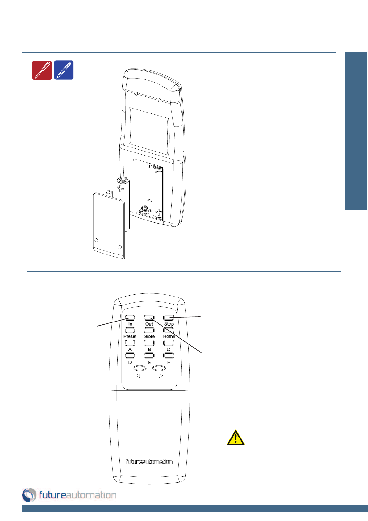
Replacing batteries
Future Automation IR Remote
Controller needs x2 AAA batteries
which are provided within the
packaging
Operation: Remote Control
Operation Buttons
In - Raises
the screen
Stop - Will stop
the operation at
any point
Out - Lowers
the screen
Safety Note
When the mechanism is moving
if you press any button apart
from IN and OUT it will stop the
operation.
Page 14 of 18 // email info@futureautomation.co.uk tel: +44 (0) 1438 833577 fax: +44 (0) 1438 833565

ET / ET60 - Electric Tilt Mechanism
SymptomCause RemedyPage
Emergency stop removed Replace emergency stop 13
Remote control or batteries
faulty
Replace batteries or remote 14
Motor or control box faulty
Apply mains power directly, via AC1
on control box
16
Incorrect pin configuration
Terminate 8-pin RJ45 to 568/b pin
configuration
12
Faulty wiring Replace connector or cable 12
Faulty control box Test contact closure on control box 12
Incorrect settings Refer to instructions 13
Incorrect pin configuration
Terminate 6-pin RJ11 to
configuration supplied
13
ASC11 protocol error Amend Protocol 13
Mechanism not working
Contact closure not working
RS232 not working
ET Electric Tilt Mechanism - Trouble shooting guide
Having problems? - Check the following:
1. Are all the connections correct?
Trouble Shooting:
If the mechanism does not operate correctly, check the items listed in the table below.
Should the problem persist, there may be a malfunction. If this is the case, disconnect the
mains power immediately and contact your installer
2. Is the mechanism being operated correctly?
Page 15 of 18 // email info@futureautomation.co.uk tel: +44 (0) 1438 833577 fax: +44 (0) 1438 833565
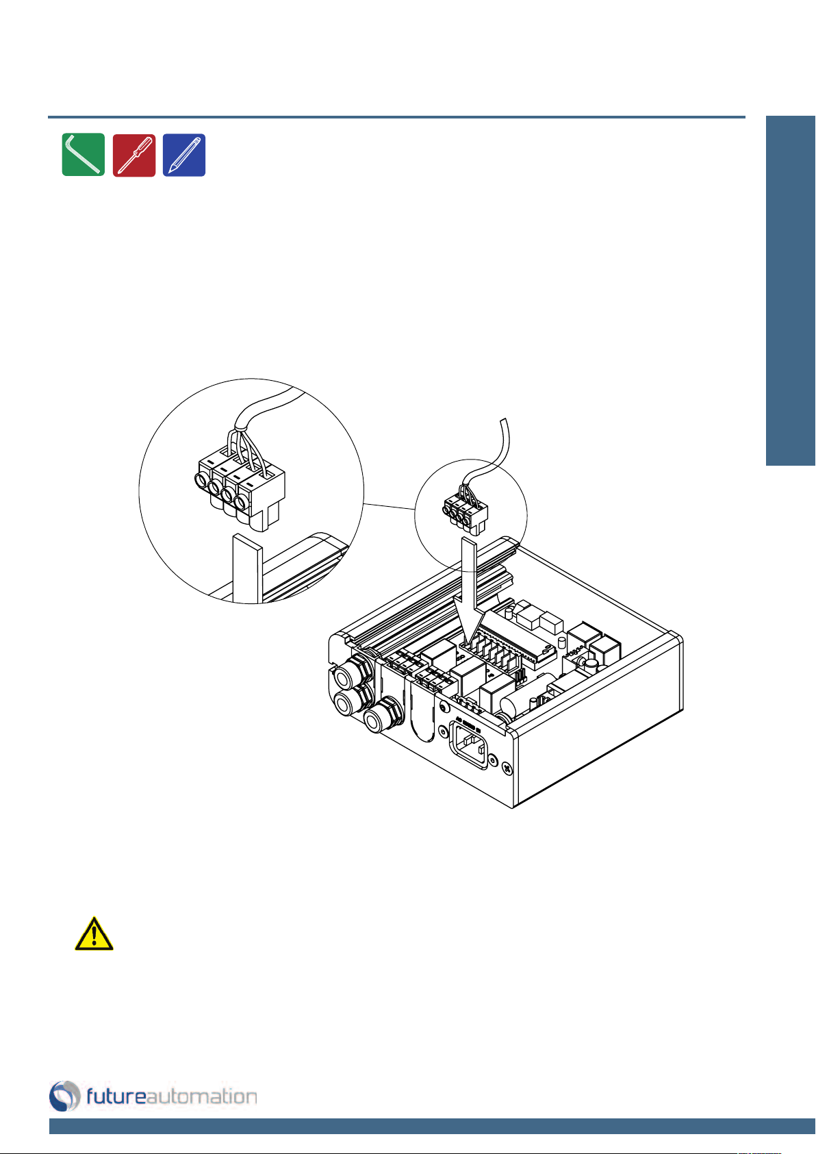
ET / ET60 - Electric Tilt Mechanism
Test motor operation
If the mechanism is not working, you can test the motor directly. To do so, you will need to
locate and open the control box.
Trouble Shooting:
CAUTION. Apply mains voltage taking all necessary grounding precautions.
Use live (brown) and switch live (black) to change direction of motor. If the
motor works, contact manufacture to replace control box.
Page 16 of 18 // email info@futureautomation.co.uk tel: +44 (0) 1438 833577 fax: +44 (0) 1438 833565

ET / ET60 - Electric Tilt Mechanism
ET ET60
Product Dimensions (W,D,H)
685x57x495mm
[27x2.2x19.5"]
685x57x605mm
[27x2.2x23.8"]
Weight (Kg) 12Kg [26.5lb] 13Kg [28.7lb]
Power Consumption 110W 110W
Power Consumption on Standby 3W 3W
Lifting Capacity 50Kg [110.2lb] 50Kg [110.2lb]
Standard Colour Black Black
Max Drop Angle 20 Degrees 20 Degrees
Screen Size Range 32" - 50" 50" - 70"
Control
IR Remote, RS232 &
Contact Closure
IR Remote, RS232 &
Contact Closure
Power Supply 240V or 110V 240V or 110V
Control of 3rd Party Product Yes Yes
Output Power supply 12V - 240V 12V - 240V
Control Box Size (W,D,H)
150x150x52mm
[5.9x5.9x2"]
150x150x52mm
[5.9x5.9x2"]
Shipping Details
Dimensions (W,D,H)
800x200x600mm
[31.5x7.9x23.6"]
800x200x700mm
[31.5x7.9x27.6"]
Weight (Kg)
15Kg [33.1lb] 16Kg [35.3lb]
A general technical overview of the ET & ET60 electric tilt bracket
Technical overview:
Page 17 of 18 // email info@futureautomation.co.uk tel: +44 (0) 1438 833577 fax: +44 (0) 1438 833565

ET / ET60 - Electric Tilt Mechanism
Notes...
This product carries a warranty that covers the cost of labour and spare parts incurred by any defects in materials and workmanship under normal use
during a two year period from date of purchase. Support for any problems that are not hardware faults are excluded from the warranty entitlement.
This warranty does not affect your statutory consumer rights.
The following is excluded from warranty service:
• Malfunctioning caused by misuse or damage, accidental or otherwise, or service modification by persons not authorised by Future Automation,
or the use of any non Future Automation supplied parts;
• Any electrical, or other environmental work external to your Future Automation mechanism including power cuts, surges or lightning strikes;
• Additional items not supplied by Future Automation although they may have been supplied together by the retailer;
• Any 3rd party software products controlling your mechanism;
• Any transfer of ownership. Warranty is provided only to the initial purchaser;
• Compensation for loss of use of the product, and consequential loss of any kind;
• Use of the product over the specified weight capacity;
• Any damage to products during transit that is not checked and notified as “unchecked” or “damaged” upon receipt of delivery.
Any part of your system that needs to be replaced during a warranty repair becomes the property of Future Automation.
Page 18 of 18 // email info@futureautomation.co.uk tel: +44 (0) 1438 833577 fax: +44 (0) 1438 833565
Product Warranty

Future Automation
Unit 2 Kimpton Enterprise Park
Claggy Road
Kimpton
Hertfordshire
SG4 8HP
United Kingdom
Tel: +44 (0) 1438 833 577
Fax: +44 (0) 1438 833 565
Email: info@futureautomation.co.uk
www.futureautomation.co.uk
 Loading...