

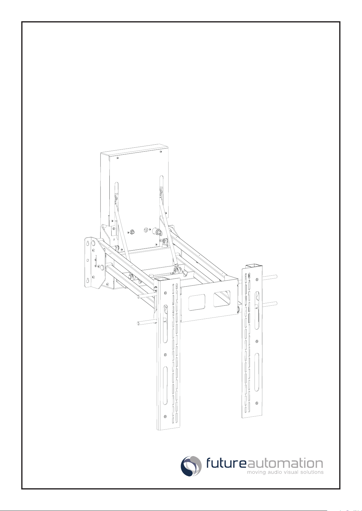
EAD3
Electric Advance and Drop TV Wall Mount
Installation Instructions
Issue 002
Safety Disclaimer
Product Safety Disclaimer - IMPORTANT SAFETY INSTRUCTIONS BELOW
WARNING: Failure to provide adequate structural strengthening, prior to installation can result in serious personal injury or damage to the
equipment. It is the installer’s responsibility to ensure the structure to which the component is axed can support four times the weight of
the component and any additional apparatus mounted to the component.
WARNING: Do not exceed the weight capacity for this product as listed below. This can result in serious personal injury or damage to the
equipment. It is the installer’s responsibility to ensure that the total combined weight of all attached components does not exceed that of
the maximum gure stated.
WARNING: Risk of death or serious injury may occur when children climb on audio and/or video equipment or furniture. A remote control
or toys placed on the furnishing may encourage a child to climb on the furnishing and as a result the furnishing may tip over on to the child.
WARNING: Risk of death or serious injury may occur. Relocating audio and/or video equipment to furniture not specically designed to
support audio and/or video equipment may result in death or serious injury due to the furnishing collapsing or over turning onto a child
or adult.
Warning – Risk of Injury!
Only for use with screens weighing
Use with heavier screens/equipment may lead to instability causing
tip over or failure resulting in death or serious injury.
Bracket Suitable for Residential and Commercial Use.
176lbs (80kg) OR LESS.
WARNING:
1. Keep all documentation/instructions after tting.
2. Read all technical instructions fully before installation and use. It is the installer’s responsibility to ensure that all documentation is
passed on the end user and read fully before operation.
3. Do not use near water or outdoors unless the product has been specically designed to do so.
4. Protect the any cables or cords being used near this bracket from being walked on or pinched to prevent damage and risk of injury.
5. Use this product only for its intended purpose as described in these instructions and only use attachments/accessories specied by
the manufacturer.
6. Refer all servicing to qualied personnel. Servicing is required regularly on an annual basis.
7. Do not operate the product if it is damaged in any way, liquid has been spilled or objects have fallen into the apparatus, the
apparatus has been exposed to rain or moisture, does not operate normally, or has been dropped. Contact the original installer/
manufacturer to arrange repair or return.
WARNING - To reduce the risk of burns, re, electric shock, or injury to persons:
1. Clean only with a dry cloth and always unplug any electrical items being used in conjunction with this product before cleaning.
Future Sound & Vision trading as Future Automation intend to make this and all documentation as accurate as possible. However, Future
Automation makes no claim that the information contained herein covers all details, conditions or variations, nor does it provide for every
possible contingency in connection with the installation or use of this product. The information contained in this document is subject to
change without prior notice or obligation of any kind. Future Automation makes no representation of warranty, expressed or implied,
regarding the information contained herein. Future Automation assumes no responsibility for accuracy, completeness or suciency of the
information contained in this document.
Page 2 of 17 // Installation Instructions - EAD3

Contents
Table Of Contents
Safety Disclaimer 2
Contents 3
Package Contents 5
Mechanism Quick-start Guide 6
Installation Instructions 7
1 - Mechanism Positioning 7
2 - Fixing To The Wall 8
3 - Screen Mounting 9
4 - Screen Position Adjustment 10
5 - Setting Mechanism Limits 11
6 - Cable Management 12
Mechanism Control 13
1 - General 13
2 - Infrared (IR) Operation 14
3 - Contact Closure Operation 15
4 - RS232 Operation 16
Contact Information 17
Page 3 of 17 // Installation Instructions - EAD3

Product Warranty
Future Automation - Product Warranty Details
Your warranty covers the cost of labour and spare parts incurred by any defects in materials and workmanship under normal use during a
two year period from date of purchase.
Under the warranty, we aim to either solve the issue remotely (via telephone or email support) or if the mechanism requires a part, arrange
a visit to your premises by a Future Automation approved engineer or send replacement items where appropriate.
Support for any problems that are not hardware or software faults are excluded from the warranty entitlement.
Warranty repairs will be carried out as rapidly as possible, but subject to parts availability.
Some things are not covered under warranty, the following is excluded from warranty service:
• Malfunctioning caused by misuse or damage, accidental or otherwise, or service modication by persons not authorised by Future
Automation, or the use of any non Future Automation supplied parts;
• Any electrical, or other environmental work external to your Future Automation mechanism including power cuts, surges or lightning
strikes;
• Additional items not supplied by Future Automation although they may have been supplied together by the retailer;
• Any 3rd party software products controlling your mechanism;
• Any transfer of ownership. Warranty is provided only to the initial purchaser;
• Compensation for loss of use of the product, and consequential loss of any kind.
Any part of your system that needs to be replaced during a warranty repair becomes the property of Future Automation.
Customer Support - Contact Details
European Oce
Address:
Unit 6-8
Brunel Road
Bedford
Bedfordshire
MK41 9TG
Phone: +44 (0) 1438 833577
Email: info@futureautomation.co.uk
Oce Hours:
Mon - Fri 8:00 to 17:30 GMT
Saturday & Sunday - Closed
North American Oce
Address:
Enterprise Park
127 Venture Drive
Dover
NH
03820
Phone: +1 (603) 742 9181
Email: info@futureautomation.net
Oce Hours:
Mon - Fri 7:00 to 17:00 EST
Saturday & Sunday - Closed
Product/Installer Details - To be Complete By Original Installer
Installer Contact Details:
Contact Address:
Contact Phone:
Contact Email:
Original Installation Date:
Product Serial Number:
Page 4 of 17 // Installation Instructions - EAD3
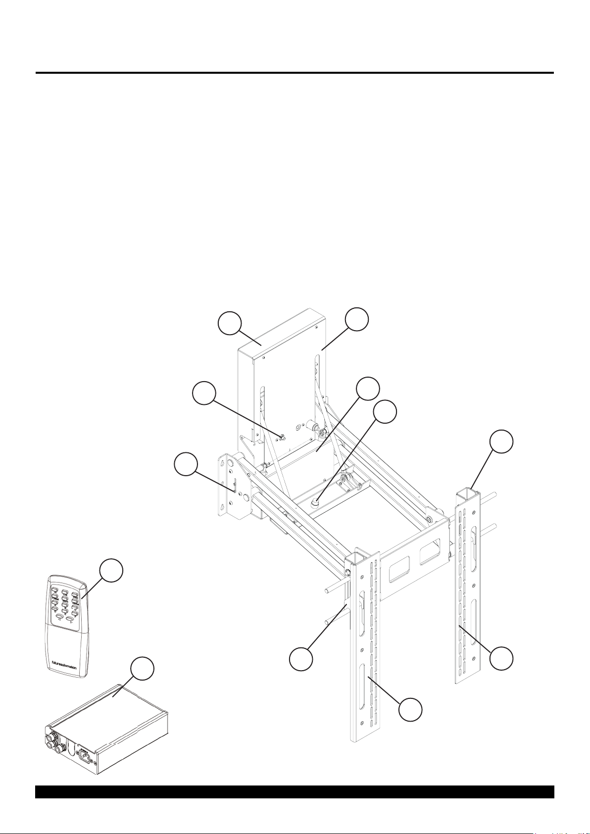
Package Contents
Package Contents:
1 - EAD3 Mechanism
1.1 - Wall Plate
1.2 - Top Cover
1.3 - Bottom Cover
1.4 - Screen Mount Uprights
1.5 - Down Position Switch
1.6 - Up Position Switch
1.7 - Up Position Switch Adjuster
1.8 - Main Uprights
2 - Control Box (Size and Style May Vary)
3 - Infrared (IR) Remote Control
Items Not Shown On Page:
4 - EAD3 Accessory Pack
4.1 - x2 AAA Batteries
4.2 - Mains Power Lead
4.3 - Infra-Ref Control Lead
4.5 - CAT5 Lead with RJ45 Connector
4.6 - Screen Fixings Pack (Multi-pack of Nuts,
Bolts and Washers)
1.1
1.6
1.5
3
1.2
1.3
1.7
1.8
2
Page 5 of 17 // Installation Instructions - EAD3
1.8
1.4
1.4
Mechanism Quick-start Guide
Quick-start Guide
Some Future Automation mechanisms may ship with the control box disconnected to prevent damage during
transit. In order to operate the mechanism, the control box will need to reconnected, then have mains power
applied along with the desired control method.
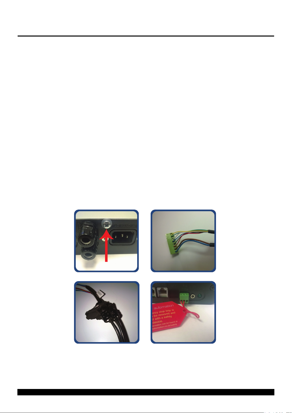
Reconnecting The Control Box
To reconnect the mechanism control box, follow the below steps:
1. Make sure the power is disconnected from the control box.
2. Remove the retaining screw and washer from the end of the control box to allow removal of the control box
lid. (Image 1 Below).
3. Slide o the control box lid to reveal the control board inside.
4. Locate the green connector on the end of the loom leading from the lift mechanism. This plug will have a
small tag attached stating the correct connecting socket on the control board (e.g. “AC1”, “DC2”...) (Image 2
Below).
5. Plug the green connector into the corresponding socket on the control board. This plug is handed and will
only connect correctly one way. Do NOT force the connector into the socket, this can cause serious damage
to the control board and mechanism.
6. Route the wiring loom out of the end of the control box by inserting the black plastic inserts into the slots
provided. (Image 3 Below).
7. Slide the control box cover back over the control board and replace the xing screw and washer.
Image 1.
Image 2.
Image 3.
Image 4.
IMPORTANT
For the mechanism to operate, the green three way safety connector with the loop of wire
attached, must also be plugged into the end of the control box. (Image 4 above). If this
connector is not plugged in, a bright red LED will be visible inside control board and the Input
Con rmation Input LED will be permanently illuminated.
Page 6 of 17 // Installation Instructions - EAD3

Installation Instructions
5.9
150
28.5
724
12.0
305
2.0
50
12.0
305
2.0
50
1 - Mechanism Positioning
Before mounting the EAD3 it is important to ensure there are no obstructions through the full travel of
the mechanism.
1. With the mechanism laid at, oer the screen onto the Screen Uprights and measure from the bottom of
the screen to the bottom of the wall plate to determine the mechanisms position on the wall.
(Note: the screen should be mounted as high up on the mechanism as possible to reduce the amount of
wall plate that remains visible behind the screen in the DOWN position.)
2. The screen must start a minimum of 50mm [2.0"] above any objects (such as a mantelpiece) that protrude
305mm [12.0"] or less from the wall - for deeper obstructions the screen must start higher.
3. Refer to page 2 of the EAD3 Technical Sheet to determine the nal wall xing hole positions.
25.4
645
22.2
564
19.1
484
5.9
150
724
28.5
12.0
305
2.0
50
27.1
689
Page 7 of 17 // Installation Instructions - EAD3
Installation Instructions
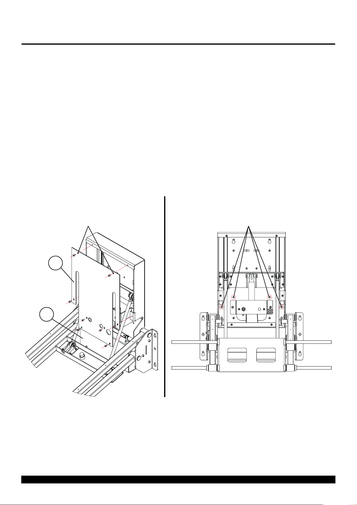
2 - Fixing To The Wall
The mechanism must be securely xed to a solid, load bearing surface using the mounting holes provided
on the mechanism's wall plate.
1. Unhook the Screen Uprights (Not Shown Below) from the Main Uprights (Not Shown Below),then remove
the Top Cover (1.2) and Bottom Cover (1.3) by removing the 8 x M5 xings shown below, to access the rear
xing holes.
2. Fix the mechanism to the wall using suitable xings (Not Provided) in as many mounting holes as possible.
Note: The highlighted xing holes shown below MUST be used in any installation.
3. The mechanism may need to be powered out to a mid position to access some central xing holes (See
Mechanism Control section of the installation instructions) - Note: this should only be done after all
other xings are in place.
1. 2.
Remove 8 x M5 Bolts
to Release Covers and
Access Mounting Holes.
1.2
1.3
Circled Fixing Holes MUST
Be Used.
Page 8 of 17 // Installation Instructions - EAD3

Installation Instructions
Measure distance between
Mount Bobbins and set
spacing of Main Uprights
on mechanism accordingly.
Switch plates over for
VESA 600 and above.
Mount Bobbin
Spacing
3 - Screen Mounting
1. Lay your screen face down on a padded surface and place the Screen Uprights (1.4 - removed in Step 2)onto
your screens four VESA mount holes. Secure using the bolts and washers provided in the Fixings Pack as
shown below. If your screen has recessed mount holes or if you need to space the uprights o for clearance,
use the spacers provided in the Fixings Pack. The standard mount conguration is VESA400 compatible, to
achieve VESA600 or wider, you will need to swap the left and right Mount Uprights (1.4) over.
2. On the back of each Mount Upright (1.4) will be three Mount Bobbins. Once the uprights are attached to
the back of the screen, measure the horizontal distance between the these Bobbins and adjust the Main
Uprights (1.8 - still attached to the EAD3) so the keyholes xings on these are the same horizontal distance
apart as the Mount bobbins.
3. Lift and hook the Screen onto the EAD3. The Mount Bobbins should locate into the keyholes on the Main
Uprights (1.8) to secure the screen to the bracket.
1./2.
1.4
3.
Page 9 of 17 // Installation Instructions - EAD3
1.8

Installation Instructions
A
DETAIL A
SCALE 1 : 2
4 - Screen Position Adjustment
1. Once the screen has been attached to the EAD3, it can be adjustment horizontally by sliding the screen and
Uprights left or right along the stainless steel Mount Bars shown below. The s lots in the Screen Uprights
(1.4) allow for vertical position adjustment by loosening screen xings and raising or lowering screen to the
desired position.
2. Tighten of the lower 2 xings on the rear of Main Uprights (1.8) will lock o horizontal adjustments.
3. The top xings on the rear of the Main Uprights (1.8) can be adjusted in or out to alter the tilt angle of the
screen (up to ±5º).
1.4
1.8
Screen Tilt Adjustment
Horizontal
Adjustment Lock
O
Mount Bars
Page 10 of 17 // Installation Instructions - EAD3

Installation Instructions
5 - Setting Mechanism Limits
The mechanism's IN position is factory set at 152mm [6"]. This is the mechanism furthest most IN
position and can only be adjusted outwards. Adjustment of the IN Switch buers is very sensitive, so
should always be adjusted in small increments for safety reasons. All IN position adjustments must be
carried out using the rubber buer ONLY and NOT the IN Switch itself.
To adjust the IN position:
1. Wind the two rubber buer stops mounted on the wall plate IN as far as possible.
2. Wind the rubber In Switch Buer in or out in small increments to adjust where the contacts hits the In
Switch.
3. Once the desired IN position has been achieved, the two rubber buer stops on the wall plate must then be
wound out to contact the upper arm rest when the bracket is in the IN position.
To adjust the OUT position:
1. Loosen the 2 x M5 Nuts on the left of the mechanism shown below to release the OUT Limit switch.
2. Slide the OUT Limit Switch UP to RAISE the OUT position or DOWN to LOWER the OUT position.
3. Once the desired OUT position has been achieved, re-tighten the 2 x M5 Nuts loosened in step 1.
Wall Plate Buers.
IN Switch - This must
NOT be adjusted.
IN Switch Buer
Page 11 of 17 // Installation Instructions - EAD3
OUT Limit Switch Slider.

Installation Instructions
250
150
100
C
L
SYM
6 - Cable Management
All Cables must be correctly managed and secured as shown below to prevent any risk of snagging or
trapping during the mechanisms normal travel.
1. The mechanism's control box will be supplied with a 2.5m [8 ' 2"] ying lead. This control box will need to
be placed in an easily accessible location for future maintenance.
2. Both screen cables and mechanism cables should ideally enter/exit the mechanism through the cable cut
cut-out in the center of the Wall Plate (1.1).
3. After entering from the Cable Cut out in the Wall Plate (1.1), cables should be routed along the underside
of the Upper Arms (following the dotted line below) and xed using cable ties secured to the tie blocks
supplied.
1.1
Page 12 of 17 // Installation Instructions - EAD3

Mechanism Control
1 - General
This mechanism has multiple standard control methods, each of which requires a di erent input method to the
control box. For ease, the input sockets on the control board are labelled below.
(Control box size and style may vary to image shown)
Control Box Inputs
RS232 (RJ11/RJ25)
Contact Closure (RJ45)
Input Con rmation LED
IR Input Jack (3.5mm)Emergency Stop Connector
Mains Voltage Input
Mechanism Emergency Stop Connector
This mechanism features an Emergency Stop Connector, which MUST be plugged into the control box in the
connector labelled above for the mechanism to operate. If this connector is not plugged in, the Input Con rmation
LED will be permanently lit. As per the red plastic tag attached to the Emergency Stop Connector (and shown
below), the small loop of wire in this connector is designed to be replaced by a third party safety mechanism.
Replacing Mechanism Batteries
The standard Future Automation Infrared (IR) remote control required x2 AAA batteries to operate. These are
provided with the mechanism in the Accessories Pack. These batteries can be replaced as the per the image
below.
Page 13 of 17 // Installation Instructions - EAD3

Mechanism Control
2 - Infrared (IR) Operation
This Mechanism can be controlled via the supplied 14 button Infrared (IR) Remote Control, pair with the supplied
Infrared (IR) lead and sensor.
The mechanism's functions can be controlled by plugging the Infrared (IR) lead and sensor into the 3.5mm IR
Input Jack shown on the General Mechanism Control page.
Con rmation of Infrared (IR) input will be shown by a single ash of the large green LED located on the end of
the control box.
As Infrared (IR) control works over line of site, the Infrared (IR) sensor must be directly viewable from what ever
location the remote control is being used from.
Infrared (IR) Remote Control Button Layout
IN - Brings the mechanism into
the cabinet.
OUT - Brings the mechanism
out of the cabinet, without
swivelling.
STOP - Will stop the operation of
the mechanism at ANY position.
IMPORTANT
Only buttons indicated above are functional with the product. Any other button press will STOP the
mechanism.
Page 14 of 17 // Installation Instructions - EAD3

Mechanism Control
3 - Contact Closure Operation
This Mechanism can be controlled via Contact Closure, utilising an 8 Pin RJ45 Connector attached to a length of
CAT5 (Type 568A or 568B) cable.
The mechanism's functions can be controlled by plugging this into the RJ45 port on the mechanism control
board, then shorting pins 1-8 on this connector as shown in the Contact Closure Input Table below.
Con rmation of Contact Closure input will be shown by a single ash of the large green LED located on the end
of the control box, as well as illumination of the corresponding Contact Closure LED on the printed circuit board
as shown below.
RJ45 Pin Layout
Contact Closure Input Table
Contact Closure LED Layout
LED 1
LED 2
LED 3
LED 4
LED 5
(NOT USED)
Contact Closure
Input Port
Page 15 of 17 // Installation Instructions - EAD3

4 - RS232 Operation
This Mechanism can be controlled via RS232, utilising a 6 Pin RJ11/RJ25 connector OR 9 Pin Serial connector
attached to a length of 6 core cable.
The mechanism's functions can be controlled by plugging this into the RJ11/RJ25 port on the mechanism control
box, then inputting the RS232 commands shown in the RS232 Input Table below.
Con rmation of Contact Closure input will be shown by a single ash of the large green LED located on the end
of the control box.
RJ11/RJ25 Pin Layout
PIN 1: RX
PIN 6: TX
PIN 3 & 4: GROUND
RS232 Programming Details
Baud Rate: 9600
Stop Bit: 1
Parity: None
Databits: 8
Serial Pin Layout
PIN 2: RX
PIN 3: TX
PIN 5: GROUND
RJ11/RJ25 Func. 9 PIN Serial Colour
PIN 1 TX-RX PIN 2 Blue
PIN 3 GROUND PIN 5 Green
PIN 4 GROUND PIN 5 Red
PIN 6 RX-TX PIN 3 White
RS232 Input Table
IMPORTANT - Ensure all protocols are entered exactly as written below, including Carriage Return (ENTER / ASCII 13)
Protocol Action
fa_in Carriage Return (Enter / ASCII 13) Device IN
fa_out Carriage Return (Enter / ASCII 13) Device OUT
fa_stop Carriage Return (Enter / ASCII 13) Device STOP (At any position)
Page 16 of 17 // Installation Instructions - EAD3

Contact Information
European Oce
Address:
Unit 6-8
Brunel Road
Bedford
Bedfordshire
MK41 9TG
Phone: +44 (0) 1438 833577
Email: info@futureautomation.co.uk
Oce Hours:
Mon - Fri 8:00 to 17:30 GMT
Saturday & Sunday - Closed
Page 17 of 17 // Installation Instructions - EAD3
North American Oce
Address:
Enterprise Park
127 Venture Drive
Dover
NH
03820
Phone: +1 (603) 742 9181
Email: info@futureautomation.net
Oce Hours:
Mon - Fri 7:00 to 17:00 EST
Saturday & Sunday - Closed
 Loading...