

Page 1

Installation Instructions
AL965 Actuator Lift
Design Highlights
-Push up lid
-Full cable management
-Compact design for minimum spatial requirements
-Only 20mm of height above television required
-Near silent motor system
Lift Mechanisms
Thank you for choosing
futureautomation
email info@futureautomation.co.uk tel: +44 (0) 1438 833577 fax: +44 (0) 1438 833565 ISSUE 012
Page 2

AL965 Actuator Lift
Safety Disclaimer
Important Safety Instructions
Explanation of graphical symbols
-(Electric Shock Symbol) = The lightning flash within an equilateral triangle is intended to alert you to the presence of un-insulated
“dangerous voltage” within the products enclosure that may be of sufficient magnitude to constitute an electric shock to persons
-(Caution Symbol) = The exclamation point within an equilateral triangle is intended to alert you to the presence of important
operating and maintenance (servicing) instructions in the literature accompanying the product
-(Tools Symbols) = The tools symbol within a coloured square are intended to highlight the required tools necessary for correct and
safe installation of the product. These are intended as a
guide only, and it is at the installer’s discretion as to which tools are used.
WARNING: RISK OF ELECTRIC SHOCK, ONLY AUTHORIZED INSTALLERS TO OPEN THE POWER CONTROL BOX.
WARNING: To reduce the risk of fire or electric shock, do not expose electrical parts to rain or moisture, unless the
product has been specifically designed to do so.
Introduction: Safety Information
WARNING: Failure to provide adequate structural strengthening, prior to installation can result in serious personal injury or damage to the
equipment. It is the installer’s responsibility to ensure the structure to which the component is affixed can support the four times the
weight of the component.
WARNING: Do not exceed the weight capacity. This can result in serious personal injury or damage to the equipment. It is the installer’s
responsibility to ensure that the total combined weight of all attached components does not exceed that of the maximum figure stated.
WARNING: Failure to provide adequate structural strength for this component can result in serious personal injury or damage to equipment! It is the installer’s responsibility to make sure the structure to which this component is attached can support five times the combined
weight of all equipment. Reinforce the structure as required before installing the component.
Warnings:
1. Read all technical instructions fully before installation and use. It is the installer’s responsibility to ensure that all
documentation is passed on the end user and read fully before operation.
2. Keep all documentation.
3. Heed all warnings.
4. Follow all technical specifications and instructions during installation.
5. Do not use near water unless the product has been specifically designed to do so.
6. Clean only with a dry cloth.
7. Do not defeat the purpose of the polarized or grounding type plug. A polarized plug has two blades, one wider
than the other. A grounding type plug has two blades and a grounding prong. The wide blade or third prong are
provided for your safety. If the provided plug does not fit your outlet, consult an electrician or contact the
manufacturer.
8. Protect the power cord from being walked on or pinched, particularly at plugs, convenience receptacles, and the
point where the exit from the apparatus.
9. Unplug the apparatus during lightning storms or when unused for long periods of time.
10. Only use attachments/accessories specified by the manufacturer.
11. Refer all servicing to qualified personnel. Servicing is required regularly on an annual basis, when the apparatus is
damaged in any way, liquid has been spilled or objects have fallen into the apparatus, the apparatus has been
exposed to rain or moisture, does not operate normally, or has been dropped.
12. To completely disconnect the apparatus form the AC mains, disconnect the power cord plug from the AC
receptacle on the power control box.
13. To prevent overheating, do not cover the apparatus. Install in accordance with the instructions.
14. UK, Ireland and Hong Kong only – The power cord is supplied with a 13A plug having an earthing pin. The
apparatus is earthed and this pin is not required for safety, merely to operate the safety shutter of mains outlet.
15. No naked flames such as lit candles should be placed on the unit.
16. Observe and follow the local regulations when disposing of batteries.
17. Do not expose the unit to dripping or splashing fluids.
18. Do not place objects filled with liquid, such as vases, on the unit.
19. Do not expose the batteries to excessive heat such as sunshine, fire or the like.
20. For all mounted apparatus, the apparatus should be installed on solid wood, bricks, concrete or solid wood
columns and battens.
21. Always turn off power at source before putting on or taking off parts and cleaning.
22. Do not use outdoors unless marked for outdoor use.
23. Exceeding the weight capacity can result in serious personal injury or damage to equipment.
Caution
Warning
Beware of
Moving Parts
Danger
Electricity
Keep Hands
Clear
Future Sound & Vision trading as Future Automation intend to make this and all documentation as accurate as possible. However, Future
Automation makes no claim that the information contained herein covers all details, conditions or variations, nor does it provide for every
possible contingency in connection with the installation or use of this product. The information contained in this document is subject to
change without prior notice or obligation of any kind. Future Automation makes no representation of warranty, expressed or implied,
regarding the information contained herein. Future Automation assumes no responsibility for accuracy, completeness or sufficiency of the
information contained in this document.
Page 1 of 18 // email info@futureautomation.co.uk tel: +44 (0) 1438 833577 fax: +44 (0) 1438 833565
Page 3

AL965 Actuator Lift
Contents Page
Introduction
Safety Information 1
Contents 2
Contents 3
Tool Indicator Icons 3
Installation
Parts List
Package Contents 4
Stage 1
Before You Start 5
Stage 2
Fixings To The Cabinet 6
Stage 3
Releasing The Screen Uprights 7
Stage 4
Inserting The Shelf 8
Stage 5
Aligning The Screen 9
Stage 6
Mounting The Screen 10
Stage 7
Adjusting The Push Bars 11
Stage 8
Final Checks 12
Electrical Connections
Contact Closure 13
IR Controls 14
RF Controls 15
Introduction: Contents
Operations
IR Control 14
Storing Positions 14
Changing Batteries 14
RF Control 15`
Trouble Shooting 16
Technical Overview 17
Page 2 of 18 // email info@futureautomation.co.uk tel: +44 (0) 1438 833577 fax: +44 (0) 1438 833565
Page 4

AL965 Actuator Lift
Introduction: Contents / Tool Indicator
Tool Indicator Icons
1. 2. 3. 4. 5. 6.
7.
8.
1. - Drill 3. - Allen Keys 5. - Screwdrivers 7. - Pencil
2. - Tape measure 4. - Spirit Level 6. - Spanners 8. - Saw
This product carries a warranty that covers the cost of labour and spare parts incurred by any defects in materials and workmanship under normal use
during a two year period from date of purchase. Support for any problems that are not hardware faults are excluded from the warranty entitlement.
This warranty does not affect your statutory consumer rights.
The following is excluded from warranty service:
• Malfunctioning caused by misuse or damage, accidental or otherwise, or service modification by persons not authorised by Future Automation,
or the use of any non Future Automation supplied parts;
• Any electrical, or other environmental work external to your Future Automation mechanism including power cuts, surges or lightning strikes;
• Additional items not supplied by Future Automation although they may have been supplied together by the retailer;
• Any 3rd party software products controlling your mechanism;
• Any transfer of ownership. Warranty is provided only to the initial purchaser;
• Compensation for loss of use of the product, and consequential loss of any kind;
• Use of the product over the specified weight capacity;
• Any damage to products during transit that is not checked and notified as “unchecked” or “damaged” upon receipt of delivery.
Product Warranty
Any part of your system that needs to be replaced during a warranty repair becomes the property of Future Automation.
Page 3 of 18 // email info@futureautomation.co.uk tel: +44 (0) 1438 833577 fax: +44 (0) 1438 833565
Page 5
AL965 Actuator Lift
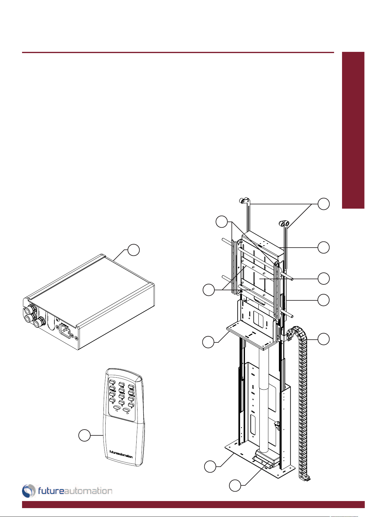
Package Contents
1 - Mechanism
1.1 - Base Plate
1.2 - Linear Actuator
1.3 - Base Shelf
1.4 - Locking Strip
1.5 - Screen Plate
1.6 - Screen Uprights
1.7 - Top Bracket
1.8 - Push Bar
1.9 - Cable Management
2 - IR Controller
5 - Control Box
Not Shown On Page
8 - x2 AAA Batteries
9 - Multi Pack Of Nuts, Bolts & Washers
10 - Mains Power & Other Leads
Nuts & Bolts Multipack:
A range of nuts, bolts, washers
and spacers to help add in the
mounting for your screen
1.6
Installation: Package Contents
1.8
3
1.4
1.3
1.7
1.5
1
1.9
2
1.1
1.2
Page 4 of 18 // email info@futureautomation.co.uk tel: +44 (0) 1438 833577 fax: +44 (0) 1438 833565
Page 6

AL965 Actuator Lift
Before you start
Prior to installation, check the following:
-The product is in good condition
-No damage to any parts
-Wiring is all secure
-The unit is in the closed position
Installation: Stage 1
-Test the mechanism by running it up and down
-Refer to pages 13-15 for mechanism control
Page 5 of 18 // email info@futureautomation.co.uk tel: +44 (0) 1438 833577 fax: +44 (0) 1438 833565
Page 7
AL965 Actuator Lift
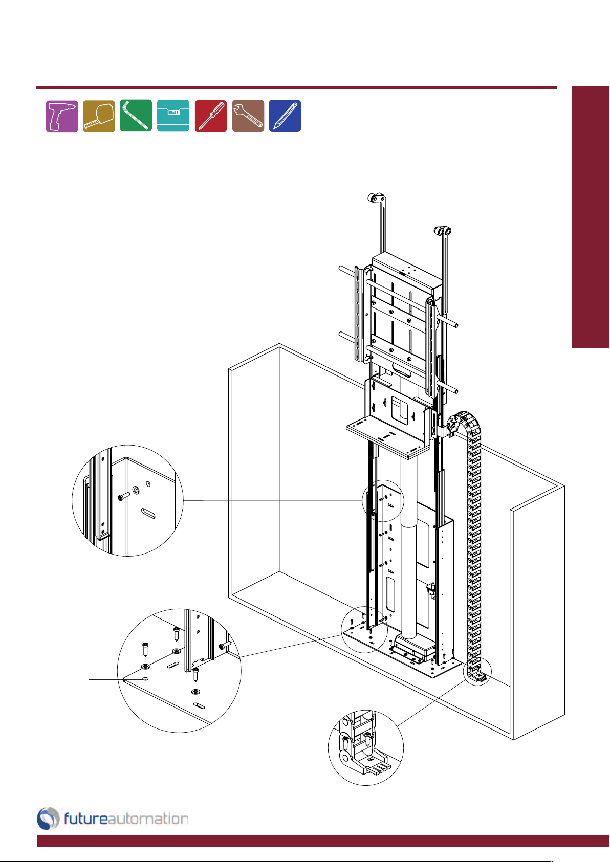
Fixing to the cabinet
-Place the mechanism into the cabinet and
fix into place,(fixings not supplied.)
- Check the measurements of the cabinet
to the technical sheet
- x9 optional fixing holes in base plate
Installation: Stage 2
Secure the mechanism
to the back of the cabinet
Fixing
holes
Secure the mechanism
to the base of the cabinet
Secure the cable management
chain to the base of the cabinet
Page 6 of 18 // email info@futureautomation.co.uk tel: +44 (0) 1438 833577 fax: +44 (0) 1438 833565
Page 8
AL965 Actuator Lift
Screen
Plates
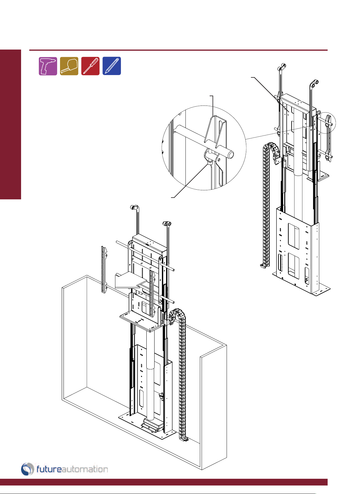
Releasing the screen uprights
Installation: Stage 3
Loosen upright bolts as
shown to release screen
uprights from the screen
plate
Upright
Bolts
Screen
Uprights
Remove screen up rights
by unhooking over the
horizontal bars
Page 7 of 18 // email info@futureautomation.co.uk tel: +44 (0) 1438 833577 fax: +44 (0) 1438 833565
Page 9

AL965 Actuator Lift
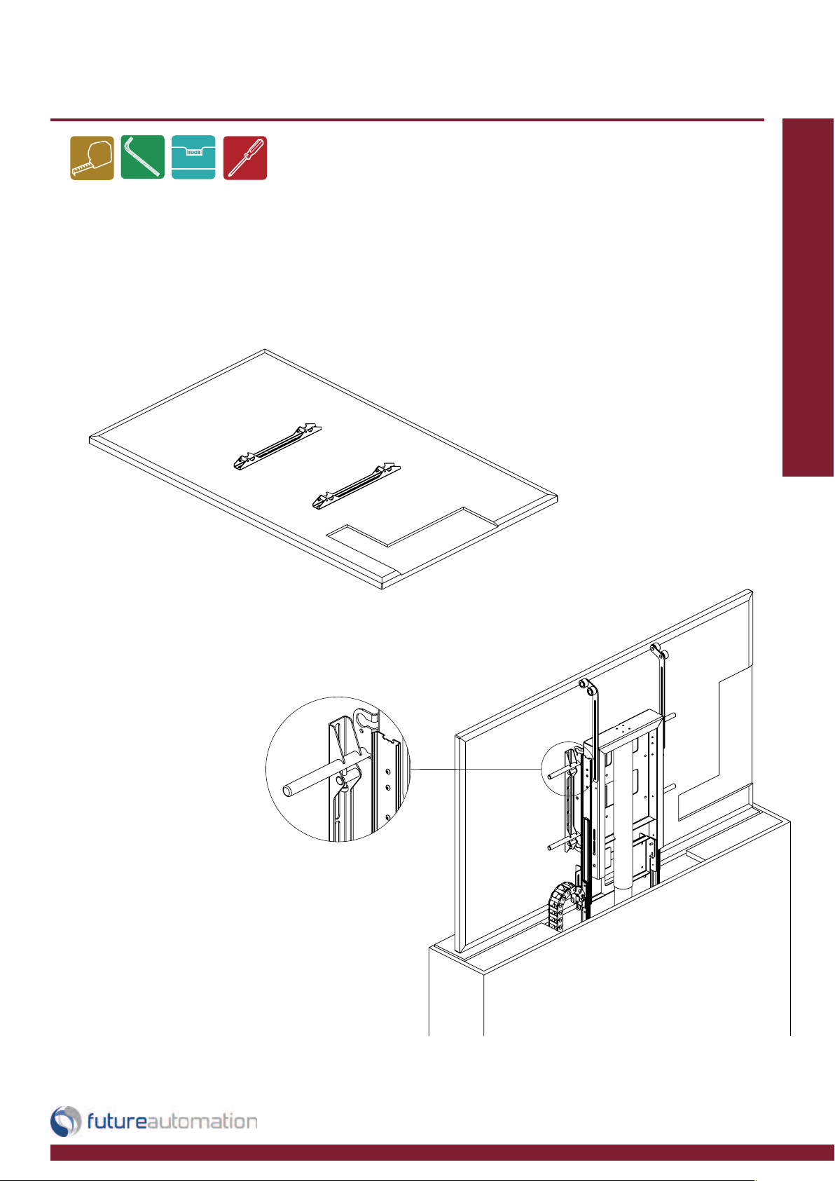
Inserting the shelf
Insert the base panel onto the shelf bracket
and fix from the underside. Loosen the nuts
shown in the detailed view to adjust the
height of the base panel.
Installation: Stage 4
Page 8 of 18 // email info@futureautomation.co.uk tel: +44 (0) 1438 833577 fax: +44 (0) 1438 833565
Page 10

AL965 Actuator Lift
Aligning the screen
Align the top of the screen so that it’s just
below the underside of the lid when the
mechanism is in the IN position
Installation: Stage 5
When the lift is fully down the screen needs
to be just under the top lid
To change the height of the screen plate
loosen the 4 nuts so the locking strips can
run freely. Move the screen plate up or
down to the desired height then tighten the
nuts back up
Nuts x8
Locking strips
Page 9 of 18 // email info@futureautomation.co.uk tel: +44 (0) 1438 833577 fax: +44 (0) 1438 833565
Mounting slots for
adjusting the screen
plate height
Page 11
AL965 Actuator Lift
M
ount
i
n
g
t
he
s
c
re
e
n
-
P
l
a
ce
t
h
e
scr
e
e
n
u
p
r
i
g
h
t
s
i
n
t
o
p
o
si
t
i
o
-
S
e
cu
r
e
i
n
t
o
p
l
a
ce
u
si
n
g
t
h
e
r
a
n
g
e
o
f
Installation: Stage 6
n
o
n
t
h
e
b
a
ck
o
f
t
h
e
scr
e
e
n
n
u
t
s,
b
o
l
t
s
a
n
d
w
a
sh
e
r
s
p
r
o
vi
d
e
d
-Once the screen uprights are attached,
overlap the screen over the horizontal bars
the same way as they were taken off
-Tighten x4 bolts back up to lock the screen
into position as shown in the detail view
-Make sure the screen is centralized in the
middle of the mechanism
Page 10 of 18 // email info@futureautomation.co.uk tel: +44 (0) 1438 833577 fax: +44 (0) 1438 833565
Page 12

AL965 Actuator Lift
Adjusting the push bars
Make sure that when the mechanism opens the push bar is in
contact with the flap at all times and that the flap does not all
Installation: Stage 7
past 90 degrees.
Approx
5mm [0. 2”]
-Loosen the 2 screws shown
above to move the push bar up
and down
-Adjust the push bar so when
the screen is in the lN position
the push bar is just short from
touching the underside of the lid
Page 11 of 18 // email info@futureautomation.co.uk tel: +44 (0) 1438 833577 fax: +44 (0) 1438 833565
Page 13

AL965 Actuator Lift
Final checks
Final movement.
Make sure the unit runs and that
the push bars hit and open the flap
smoothly
-Make sure that the lid doesn’t
fall back over its self when the
unit opens.
-Product is level and square in
the cabinet
-The mechanism runs smoothly
and to the stored positions
Installation: Stage 8
The mechanism movement should
look like this:
Page 12 of 18 // email info@futureautomation.co.uk tel: +44 (0) 1438 833577 fax: +44 (0) 1438 833565
Page 14

AL965 Actuator Lift
SLQV
568A 568B
1 12V SUPPLY 12V SUPPLY - CURRENT LIMITED W/G W/O
2 12V LATCH
When 12V attached, device will go OUT.
When 12V removed device will go IN.
GO
3GROUND GROUND W/OW/G
4 PIN 4 NOT USED BL BL
5 DEVICE LATCH
Momentary short to GROUND (pin 3), stops
device in current position.
W/BL W/BL LED 4
6 DEVICE STOP
Momentary short to GROUND (pin 3), stops
device in current position.
O G LED 3
7 DEVICE OUT
Momentary short to GROUND (pin 3), makes
device go OUT.
W/BR W/BR LED 2
8 DEVICE IN
Momentary short to GROUND (pin 3), makes
device go IN.
BR BR LED 1
PIN
DESCRIPTION
ACTION
WIRE / CABLE
CONTACT CLOSURE
LED INDICATOR
Contact Closure
- Use an RJ45 connector in the
appropriate socket on the control
box to operate via contact closure
Installation: Electrical Connection
Page 13 of 18 // email info@futureautomation.co.uk tel: +44 (0) 1438 833577 fax: +44 (0) 1438 833565
Page 15
AL965 Actuator Lift
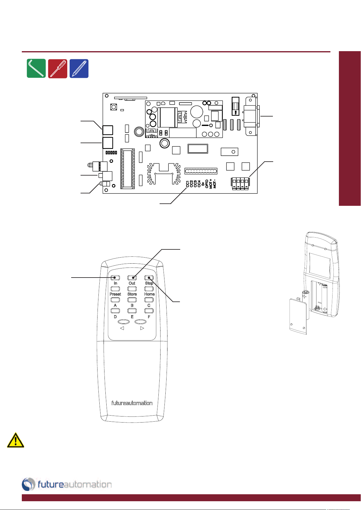
IR Controls
General Wiring
Installation: IR Control
RJ11 Connection
for RS232
RJ45 Connection
for Contact Closure
IR Input Jack
IR LED
In - Lowers
the screen to
stored position
DC1
Low voltage power output for motor
drive. LED’s to show operation of limit
switches and positional counters
Out - Raises
the screen to
stored position
AC Mains
Power Input
AC Mains
Power Output
Replacing batteries
Safety Note
When the mechanism is moving, if any button
is pressed apart from those already assigned,
the mechanism will stop immediately.
Stop - Will stop
the operation at
any point
Future Automation IR Remote
Controller needs x2 AAA batteries which
are provided within the packaging
Storing positions
Press STORE + STORE + C to set
height, current position will be stored
after lift has fully lowered uninterrupted.
An interruption of this movement will
cancel height setting.
Press STORE + STORE + B to clear
set height.
Page 14 of 18 // email info@futureautomation.co.uk tel: +44 (0) 1438 833577 fax: +44 (0) 1438 833565
Page 16

AL965 Actuator Lift
RF Controls
The RF aerial is integrated
into the circuit board.
Installation: RF Control
If power is cut the
mechanism can only
go down.
Press - Stops
Press STORE + STORE + C to set height, current position will be
An interruption of this movement will cancel height setting.
Moves
mechanism
UP
mechanism
stored after lift has fully lowered uninterrupted.
Press STORE + STORE + B to clear set height.
RF Remote Control
Moves
mechanism
DOWN
Press - Stops
mechanism
Storing positions
Mechanism Output Power Supply
It is possible for the power to the screen to be switched by the
control box. Use this connector to take power to the screen.
Earth
Live
Neutral
Page 15 of 18 // email info@futureautomation.co.uk tel: +44 (0) 1438 833577 fax: +44 (0) 1438 833565
Page 17

AL965 Actuator Lift
SLQV
RS232
- Use an RJ25 connector in the socket marked
RS232 on the control box to operate using RS232
Details
Baud rate: 9600
Stop bit: 1
Parity: None
Databits: 8
PIN 3: GROUND TO PIN 5: GROUND
PIN 4: GROUND TO PIN 5: GROUND
IMPORTANT
Ensure protocol is entered exactly
as written.
Trouble Shooting:
RJ25 9 PIN D
PIN 1: RX TO PIN 2: TX
PIN 6: TX TO PIN 3: RX
Protocol Action
fa_in Carriage Return (Enter ) Device IN
fa_out Carriage Return (Enter ) Device OUT
fa_stop Carriage Return (Enter ) Device STOP (At any position)
Pin 1: RX
Pin 6 : TX
Pin 3 & 4: GROUND
Pin 2: TX
Pin 3: RX
Page 16 of 18 // email info@futureautomation.co.uk tel: +44 (0) 1438 833577 fax: +44 (0) 1438 833565
Pin 5: GROUND
Page 18
AL965 Actuator Lift
SymptomCause RemedyPage
IR receiver not plugged in
Connect IR receiver into 'IR IN' on
interface
15
Remote control or batteries
faulty
Replace batteries or remote 15
Control unit faulty Contact manufacture
Lid falls back when open Incorrect cabinet dimensions Check cabinet dimensions 13
Rubbing noise when opening
Push bars not at equal
distance from flap
Re-position push bar 12
Remote control faulty or
batteries
Replace batteries or remote 15
Procedure not followed
correctly
Refer to instructions 15
Lift not working
Unable to store positions
Actuator lift 965 - Trouble shooting guide
Having problems? - Check the following:
1. Are all the connections correct?
2. Is the mechanism being operated correctly?
Technical overview:
If the mechanism does not operate correctly, check the items listed in the table below.
Should the problem persist, there may be a malfunction. If this is the case, disconnect the
mains power immediately and contact your installer
Page 17 of 18 // email info@futureautomation.co.uk tel: +44 (0) 1438 833577 fax: +44 (0) 1438 833565
Page 19

AL965 Actuator Lift
AL965
Product Dimensions (W,D,H When
Closed & Fully Assembled)
740x230x800mm
[29.1x9.1x31.5"]
Weight (Kg) 20Kg [44.1lb]
Power Consumption Max 200W
Power Consumption On Standby 3W
Lifting Capacity (Kg) 50Kg [110.2lb]
Standard Colour Black
Drop Distance 965mm [38"]
Max Television Size (W,H) 1750x965mm [68.9x38"]
Control
IR Remote, RF Remote &
Contact Closure
Power Supply 240V or 110V
Control Of 3rd Party Product No
Output Power Supply Yes
Control Box Size (W,D,H) 210x150x50mm [8.3x5.9x2"]
Shipping Details
Dimensions (W,D,H)
1100x380x860mm
[43.3x15x33.9"]
Weight (Kg) 45Kg [99.2lb]
A general technical overview of the AL965 actuator lift
Technical overview:
Notes...
Page 18 of 18 // email info@futureautomation.co.uk tel: +44 (0) 1438 833577 fax: +44 (0) 1438 833565
Page 20

Future Automation
Unit 2 Kimpton Enterprise Park
Claggy Road
Kimpton
Hertfordshire
SG4 8HP
United Kingdom
Tel: +44 (0) 1438 833 577
Fax: +44 (0) 1438 833 565
Email: info@futureautomation.co.uk
www.futureautomation.co.uk
 Loading...