

Page 1
WXTECH
Technical Instructions Printers OEM Info Tools 1
CORPORATE
LOS ANGELES, USA
U
S 1 800 394.9900
Int’l +1 818 837.8100
FAX 1 800 394.9910
Int’l +1 818 838.7047
ATLANTA, USA
U
S 1 877 676.4223
t’l +1 770 516.9488
In
FAX 1 877 337.7976
Int’l +1 770 516.7794
DALLAS, USA
US 1 877 499.4989
Int’l +1 972 840.4989
FAX 1 877 774.1750
Int’l +1 972 840.1750
MIAMI, USA
US 1 800 595.429
Int’l +1 305 594.3396
FAX 1 800 522.8640
Int’l +1 305 594.3309
NEW YORK, USA
US 1 800 431.7884
Int’l +1 631 345.0121
FAX 1 800 431.8812
Int’l +1 631345.0690
SANFORD,USA
US 1 800 786.9049
Int’l +1 919 775.4584
FAX 1 800 786.9049
Int’l +1 919 775.4584
TORONTO, CAN
CAN 1 877 848.0818
Int’l +1 905 712.9501
FAX 1 877 772.6773
Int’l +1 905 712.9502
BUENOS AIRES, ARG
ARG 0810 444.2656
Int’l +011 4583.5900
FAX +011 4584.3100
MELBOURNE, AUS
AUS 1 800 003. 100
Int’l +62 03 9561.8102
X 1 800 004.302
A
F
Int’l +62 03 9561-7751
SYDNEY, AUS
US 1 800 003.100
A
Int’l +62 02 9648.2630
FAX 1800 004.302
Int’l +62 02 9548.2635
MONTEVIDEO,URY
URY 02 902.7206
Int’l +5982 900.8358
FAX +5982 908.3816
JOHANNESBURG, S.A.
S.A. +27 11 974.6155
FAX +27 11 974.3593
Canon LBP-2460
Data Products DD524
P 5Si, 5Si MX, 5Si Mopier
H
IBM Network Printer 24
Lexmark Optra N Model 240
QMS 2425-2425 EX
Troy 524
Photo 1
Photo 2a
Photo 2b
Part Number: C3909A
Gram Load: 840 grams
Yield @ 5%: 15,000 pgs
Pages/Min.: 24ppm
Resolution: 600 dpi
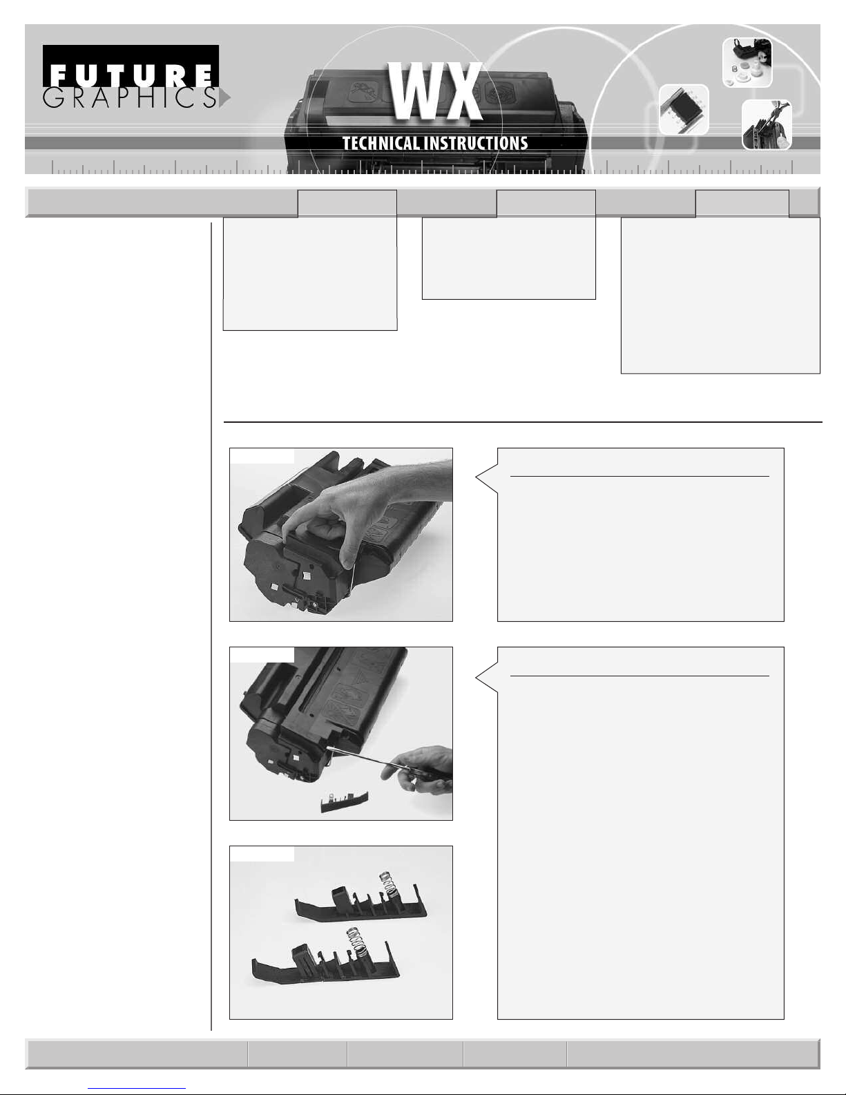
Step 1
Locate and remove the cartridge clips on
both sides of the cartridge using your finger. Gently pry up on the clip until it pops
up.
(See Photo 1)
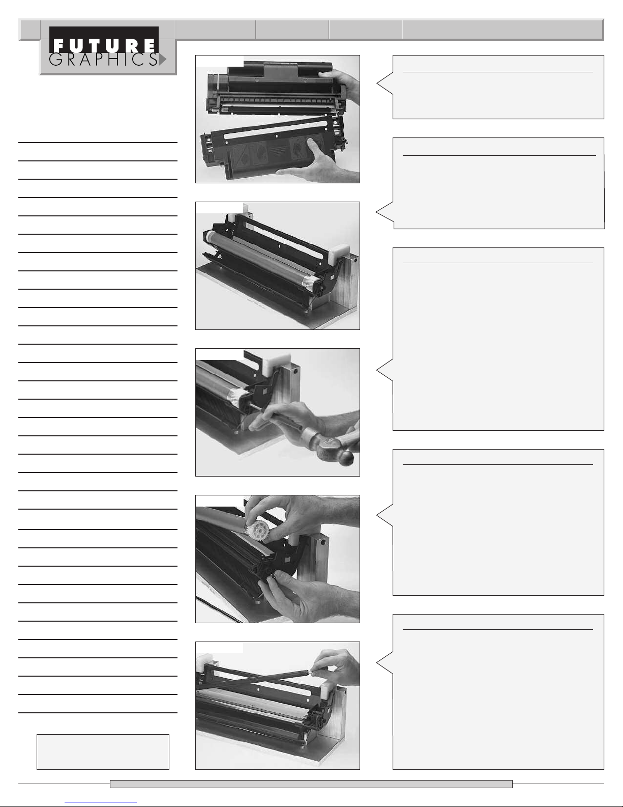
ep 2
St
Using a flat blade screwdriver, pry up on
the other clip and remove it.
(See Photo 2a)
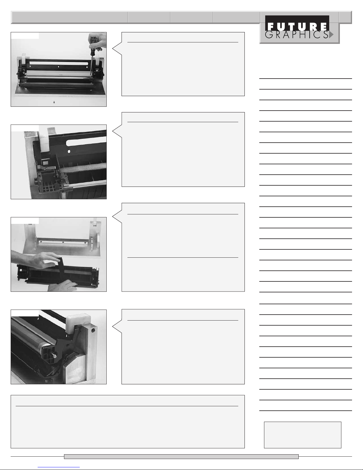
NOTE: I
eak while the
br
these break, replace with aftermarket
part. You may need to use the springs
om the OEM clip
fr
(See Photo 2b)
Needle Nose Pliers
mall Flat Blade Screwdriver
S
#2 Phillips Head Screwdriver
Small Hammer
Soft Lint-Free Cloth/ Damp Cloth
5/32” Drift Punch
Anhydrous Isopropyl Alcohol
800gms 5Si Toner
Nu-Finish (optional)
Damp Cloth
t is very likely that these clips will
eing removed. If
e b
y ar
.
E-mail: info@futuregraphicsllc.com Website: www.futuregraphicsllc.com
Page 2
2 WX Technical Instructions
Notes
Photo 3
Photo 4
Photo 5
Step 3
Just like the HP4 cartridge, the two halves
of the cartridge can now be separated.
(See Photo 3)
Step 4
Set the hopper aside. If you have a waste
hopper fixture, set the waste hopper in the
fixture. If not, place the waste hopper on
the table.
(See Photo 4)
Step 5
The drum axle is a metal rod that goes
through the center of the drum end to
end. On the large gear end of the axle is a
small white plastic retaining ring. Using a
drift punch and a hammer, tap directly on
the shaft (large gear side) and drive it out
the other end. (See Photo 5)
NOTE: Make sure you don’t lose the retaining ring. The ring fits into a groove on the
drum shaft to hold the shaft in position.
Repeated removal will wear this ring and
the ring will no longer snap into position.
If the ring does not snap, replace it.
Need trust-worthy, detailed Technical
Instructions for another engine?
Visit: www.futuregraphicsllc.com
o 6
hot
P
Photo 7
ep 6
St
Remove the drum, blow off excess toner
with compressed air and clean with isopropyl alcohol. Wrap the drum in a protective paper or cloth and set it aside in a dark,
ted place. (S
ec
ot
pr
ee P
o 6)
hot
NOTE: We were able to use the OEM drum
ter the Oem cycle with no loss in
e af
onc
density, however, you may choose to
recoat or replace the drum after the first
recharge.
Step 7
Remove the primary charge roller from its
lean clips with isopr
clips.
C
and a cotton swab. Inspect the primary
charge roller for damage. Clean the pri-
y charge roller with a mild soap and
mar
water and set it aside.
ee Photo 7)
(S
NOTE: We have had no problems using the
OEM primary charge roller three cycles in
mild weather climates.
opyl alcohol
Page 3
WX Technical Instructions 3
Photo 8
Photo 9
S
tep 8
Remove the two Phillips head screws holding the wiper blade and remove the blade.
Be careful not to break the plastic positioning posts.
(See Photo 8)
Step 9
Empty out the waste toner and clean felts
and foam with a vacuum or compressed
air.
(See Photo 9)
NOTE: Be careful not to damage felts,
foam or the mylar recovery blade, as this
can cause leaks. If the felts or foam are
damaged or worn, replace.
Notes
Photo 10
hoto 12
P
Step 10
Apply OPC protector felt to the drum
shutter door. You will need to remove the
cartridge from the fixture.
(See Photo10)
Step 11
Apply padding powder on wiper blade
and reinstall.
NOTE: If you are going to use a new aftermarket drum, always replace wiper blade.
Step 12
Apply padding powder to the OPC drum
and install. The big helical gear will go on
the right side of the waste hopper. Install
the drum axle only far enough to hold the
drum against the wiper blade. Rotate
drum so the wiper blade wipes the
padding powder off the drum.
(See Photo12)
Step 13
Once again, remove the drum axle and the drum. Reinstall the primary charge roller
then reinstall the drum and drum axle.
NOTE: When reinstalling the drum axle, the axle slides through the drum from the
left side. Make sure you install the axle in the right way. The notched end of the axle
goes on the large gear end.
N
eed help with a particular remanu-
facturing problem?
Call the Technical Resource Center from
8am - 5pm PST: 800 394.9900
Page 4

4 WX Technical Instructions
Notes
Photo 14
Photo 17
Photo 18
Step 14
Install the retaining ring.
(See Photo 14)
Step 15
Set waste hopper aside and cover.
Step 16
If you have a toner hopper fixture, place
toner hopper in fixture or place toner
hopper on the workbench.
Step 17
Remove the two screws holding the end
cap on the gear side of the toner hopper.
(See Photo 17)
Step 18
Before removing the end cap, lift the bias
strip off its positioning post next to the
doctor blade.
(See Photo 18)
Need trust-worthy, detailed Technical
Instructions for another engine?
Visit: www.futuregraphicsllc.com
o 19
hot
P
Photo 20
Step 19
Slide the end cap off. Note the position of
the white gears, then remove the four
largest ones and set them aside.
(See Photo 19)
Step 20
n the c
ur
T
two screws that hold the other end cap
on and remove.
(See Photo 20)
artridge around. Remove the
Page 5

WX Technical Instructions 5
Photo 21a
Photo 21b
Step 21
Lift out mag roller. Remove the mag roller
tabilizer, mag roller sleeve bearing and
s
mag roller sleeve bushing from the nongear side of the mag roller and clean.
(See Photo 21a and 21b)
Use compressed air or a vacuum and
remove the extra toner off the mag roller.
Use mag roller cleaner to remove any
residue built up on mag roller.
NOTE: If you are going to have your mag
rollers coated or replaced, you’ll need to
remove the mag roller contact, the gear,
mag roller stabilizer, the bearing and the
bushing from the other side of the mag
oller.
r
To remove the gear off the mag roller, use
a very small flat blade screwdriver to pry
back the prong on the gear. Remove the
non-gear side hub and send in mag roller
to be coated.
The mag roller bearings have a difference
in the inner diameter size and are not
interchangeable. HP also made two different mag rollers. The only difference is
in the length of the shaft and the hub.It
is very important to keep the parts
together. The long shaft uses a shorter
hub. When the mag rollers are put
together correctly,they can be used interchangeably in different cartridges.
Notes
o 22
hot
P
Photo 23
Step 22
Remove the two screws that hold the
doctor blade and lift it out. Clean and set
he doctor blade can wear out
T
.
aside
after a few cycles, check and replace if
necessary.
(See Photo 22)
ep 23
St
Turn the cartridge around to the gear
side once again. Remove the two other
gears. Remember which gear goes
where. These gears turn the toner paddle
bars inside the toner hopper. The bars
will fall into the toner hopper. Remove
these t
t
oner paddle bars from inside the
.
oner hopp
er
(S
ee P
hot
o 23)
N
eed help with a particular remanu-
facturing problem?
Call the Technical Resource Center from
8am - 5pm PST: 800 394.9900
Page 6

6 WX Technical Instructions
Notes
Photo 24
Photo 25
Photo 26
S
tep 24
The bars are the same so don’t worry
about getting them mixed up. Also,
emove the toner paddle bar felt washers.
r
Look at the washers to make sure toner is
not leaking through them. After a few
cycles, these felt washers will wear out
and need to be replaced.
(See Photo 24)
Step 25
Remove toner sensing bar. Make sure you
don’t lose the toner sensor bar seal. Clean
the sensor bar with a cloth and alc
NOTE: Do not bend the sensor bar.
(See Photo 25)
ohol.
Step 26
Remove leftover toner and clean the felts
and foam seals with compressed air or
vacuum. Be careful not to damage any of
the foam, felt strips, or the thin mylar strip
on the bottom lip of the toner hopper. If
these are damaged, the cartridge will
leak.
(See Photo 26)
hoto 27
P
Photo 28a
Step 27
At this point, if you are not going to seal
this cartridge, you can fill it with toner
now through the mag roller opening
then start reassembling cartridge.
(See Photo 27)
If you wish to split and seal the toner hop-
er first, proceed to the next step.
p
Step 28
Place cartridge in splitter fixture. Hold
cartridge in place and slide cutting unit
along the guide t
.
split
hoto 28a)
ee P
(S
o ensur
e a good clean
Page 7

WX Technical Instructions 7
Photo 28b
Photo 29
Photo 30
S
tep 28 cont.
NOTE: The two halves of the toner hopper
are still held together by two pins.
arefully pull the two halves apart.
C
See Photo 28b)
(
Step 29
Use a razor knife to cut off plastic posts at
the base on the non-plug side of the cartridge. These are removed so a seal can
be used.
ee Photo 29)
(S
Step 30
Using needle nose pliers,pinch the retaining clips of the agitator, and remove the
agitator drive assembly. Remove the
toner agitator felt washer. If toner is leaking through opening, replace the washer.
(See Photo 30)
Notes
o 31
hot
P
Photo 32
Step 31
Use isopropyl alcohol and clean surface
of toner hopper where cartridge was
.
split
o 31)
hot
ee P
(S
Step 32
Remove backing from the seal. With the
tail of the seal on the lef
idge (the plug side),
tr
t side of the c
e seal t
adher
toner hopper.
o 32)
hot
ee P
(S
TE:Use your finger to press around
NO
the seal t
o mak
e sur
e of a go
od adhesion.
ar
o the
-
N
eed help with a particular remanu-
facturing problem?
Call the Technical Resource Center from
8am - 5pm PST: 800 394.9900
Page 8

8 WX Technical Instructions
Notes
Photo 33
Photo 34
Photo 35
S
tep 33
Remove fill plug and fill with toner.
See Photo 33)
(
Step 34
Use compressed air or a vacuum and
clean the toner hopper seal channel end
oam on the back of the mag roller sec-
f
tion. Wipe off the back of the mag roller
section.
(See Photo 34)
NOTE: If these foam pads are damaged,
they need to be replaced.
Step 35
These foam strips stop the cartridge from
leaking after it has been split. The foam
strips are applied right across the seal
channel end foam.
(See Photo 35)
hoto 36
P
Photo 37
Step 36
Fold the seal back across the toner hopper. Now re-join the mag roller section
and the toner hopper section.
(S
ee Photo 36)
NOTE: The posts on the mag roller section
needs to fit back into the holes on the
oner hopper section.
t
Step 37
Using the toner hopper clips, clip the two
sections together.
o 37)
hot
ee P
(S
Page 9

WX Technical Instructions 9
Photo 38
Photo 39
Photo 40
S
tep 38
Reinstall the toner paddle bar felts and
the bar gears that hold them in. Then
nstall toner sensor bar.
i
See Photo 38)
(
Step 39
Put a little fresh toner on the doctor blade
and reinstall.
(See Photo 39)
Step 40
Place the mag roller bushing, mag roller
bearing,and the mag roller stabilizer back
on the mag roller. Install mag roller back
onto toner hopper.
(See Photo 40)
Notes
o 41
hot
P
Photo 42
Step 41
Reinstall all the gears on the toner hopper.
(See Photo 41)
ep 42
St
Now install the gear side end cap, aligning the “flat sided shaft” of the magnet
with its “D”shaped hole and the positioning pins thr
ough the mag r
holes and then pr
ess do
oller stabiliz
Install t
wn.
Phillips head screws. Align the metal bias
o the plastic pin next to the doctor
ap t
str
osition so tha
o p
t
blade and pr
ess in
contacts the doctor blade.
o 42)
hot
ee P
(S
er
w
t it
o
N
eed help with a particular remanu-
facturing problem?
Call the Technical Resource Center from
8am - 5pm PST: 800 394.9900
Page 10

10 WX Technical Instructions
Notes
Photo 43
Photo 45
S
tep 43
Do the same with the end cap on the
other side and apply pull tab to seal.
(See Photo 43)
Step 44
Align the toner hopper and waste hopper
assemblies together.
Step 45
Snap the OEM or aftermarket cartridge
clip back into position.
(See Photo 45)
Future Graphics (FG) is a distributor of compatible replacement parts and products for imagining equipment. None of FG's
o
pr
duc
ts ar
e genuine OEM r
eplac
emen
ts and no affilia
t par
onsorship is to be implied between FG and any OEM.
tion or sp
E-mail: info@futuregraphicsllc.com Website: www.futuregraphicsllc.com
 Loading...