

Page 1

510 REV03 REV DATE: 08/20/2013
USER MANUAL
Page 2

CONTENTS
570 REV03 REV DATE: 08/20/2013 2 Stellato
1 General ................................................................................................................................................................................ 4
Operating Safety Warnings ..................................................................................................................................................... 5
Features ................................................................................................................................................................................... 6
Safety Inspection Checklist ...................................................................................................................................................... 7
Troubleshooting ...................................................................................................................................................................... 9
Labels ..................................................................................................................................................................................... 10
2 Front Riggings .................................................................................................................................................................... 11
Installing: ............................................................................................................................................................................... 11
Removing: .............................................................................................................................................................................. 12
3 Foot Plate Height Adjustment ........................................................................................................................................... 13
4 Elevating Leg Rest Operation ............................................................................................................................................ 14
5 Arms .................................................................................................................................................................................. 15
6 Flip up Arm Rests .............................................................................................................................................................. 16
7 Replacing Upholstery ........................................................................................................................................................ 17
REPLACING THE SEAT UPHOLSTERY ...................................................................................................................................... 17
REPLACING THE BACK UPHOSTERY ....................................................................................................................................... 18
8 Rear Wheel Adjustments .................................................................................................................................................. 19
9 Unfolding and Folding the Wheel Chair ............................................................................................................................ 21
Unfolding: .............................................................................................................................................................................. 21
Page 3

CONTENTS
570 REV03 REV DATE: 08/20/2013 3 Stellato
10 Front Casters ..................................................................................................................................................................... 22
INSTALLING/REPLACING FRONT CASTERS AND FORKS ......................................................................................................... 22
Adjusting Front Caster Angle ................................................................................................................................................. 23
11 Anti-Tippers ....................................................................................................................................................................... 24
Installing/Adjusting The Anti-Tippers .................................................................................................................................... 24
Installing Anti-Tippers............................................................................................................................................................ 25
ADJUSTING THE ANTI-TIPPERS .............................................................................................................................................. 26
12 Wheel Locks Operation ..................................................................................................................................................... 27
ADJUSTING THE PATIENT OPERATED WHEEL LOCKS – .......................................................................................................... 28
13 Operating Information ...................................................................................................................................................... 29
14 Weight Training ................................................................................................................................................................. 31
15 Warranty ........................................................................................................................................................................... 32
Page 4
1 GENERAL
570 REV03 REV DATE: 08/20/2013 4 Stellato
1 General
NOTE: Check all parts for shipping damages before using.
In case of damage, do NOT use the equipment.
Contact the Equipment Supplier for further instructions.
WARNING:
DO NOT install this equipment without first reading and understanding
this instruction booklet. If you are unable to understand these
instructions, contact a healthcare professional, dealer or technical
personnel before attempting to install this equipment - otherwise, injury
or damage may occur.
NOTE: Information contained within this document is subject to change
without notice.
Page 5

1 GENERAL
570 REV03 REV DATE: 08/20/2013 5 Stellato
Operating Safety Warnings
Please read and obey all instructions and warnings listed in this manual, ignoring these warnings could result in serious
injury to the patient or attendants.
Ensure anti-tippers are always installed in the correct position when using the wheelchair.
Never lift the wheelchair by the armrests or front rigging.
Any change of seat depth may require repositioning of the rear wheels; always test the stability of the chair before use.
Never stand on the footplates during transfers in and out of the wheelchair.
Ensure wheel locks are fully engaged while stopped on any incline/decline and while patient is transferring to and from
the wheelchair.
Never tilt the wheelchair on two wheels without assistance. When in any tilt or recline position, this chair must be
operated by an attendant.
Never use the wheel locks to stop a moving wheelchair.
It is not recommended to transport users in vehicles of any kind while seated in the wheelchair. Do not use any kind of
wheelchair Tie-Down restraints that are not approved by the FDA.
Page 6

1 GENERAL
570 REV03 REV DATE: 08/20/2013 6 Stellato
Features
SPECIFICATIONS
FEATURES
SEAT WIDTHS: 14”-20”, 22”
SEAT DEPTHS: 15” – 20”
CHAIR DEPTH: Seat width +9”
SEAT TO FLOOR HEIGHT
Small frame: 13 ¼ “ – 18”
Large frame: 15 ½” – 19”
REAR WHEELS: 20”, 22” or 24” composite urethane
CASTER SIZE: 4”, 5”, 6”, 7”, 8” Urethane
BACK HEIGHTS: 19” – 22” Low, 22” – 25” High
BACK STYLE: Slip on back upholstery
ADJUSTABLE BACK ANGLE: -5
o
, 0o 7o, 14o, 21o
ARM STYLES: Full length adjustable T-Style or Flip
back.
FRONT RIGGINGS: Pin Style, swing away, dual swing
away elevating headrests
WEIGHT CAPACITY: 250lbs (114kg)
PRODUCT WEIGHT: 31 lbs.
OVERALL DIMENSIONS: 18” x 16” tilt, 16” STF)
FRAME COLORS: Black or Silver
Adjustment of caster housing angle.
Removable rear wheels with stainless steel or
plastic coated hand rims.
60 or 70 swing away upgraded front riggings
Aluminum or composite foot plates
Wheels locks push or pull to lock with extension
handles
Adjustable rear anti-tippers
Optional quick release axles
Heel loops
FRAME: Lightweight Aluminum
Page 7

1 GENERAL
570 REV03 REV DATE: 08/20/2013 7 Stellato
Safety Inspection Checklist
Initial adjustments should be made to suit your personal body structure needs and preference. Thereafter follow these
maintenance procedures:
Item
Initially
Weekly
Monthly
Periodically
GENERAL
Wheelchair rolls straight (no excessive drag or pull
to one side)
√
√
FRAME AND CROSSBRACES
Inspect for loose or missing hardware
Inspect for bent frame or cross braces
√
√
√
√
WHEEL LOCKS
Do not interfere with tires when rolling
Pivot points free of wear and looseness
Wheel locks easy to engage
Wheel locks prevent chair from moving when
engaged
√
√
√
√
√
√
√
√
SEAT AND BACK
Inspect for rips or sagging
Inspect for loose or broken hardware
Inspect cane and hand grips for wear/looseness
√
√
√
√
√
√
Page 8

1 GENERAL
570 REV03 REV DATE: 08/20/2013 8 Stellato
TIRES
Inspect for flat spots, cracks and wear
Caution: as with any vehicle, the wheels and tires
should be checked periodically for cracks and
wear and should be replaced.
√ √
√
REAR WHEELS
If equipped, quick-release axles lock properly
No excessive side movement or binding when
lifted and spun
Inspect for cracked, bent or broken spokes
√
√
√
√
√
√
HANDRIMS
Inspect for signs of rough edges or peeling
√
√
FRONT CASTERS/FORKS
Inspect axle assembly for proper tension by
spinning caster; caster should come to a gradual
stop
Adjust bearing system if wheel wobbles or binds
to a stop. Ensure wheel bearings are clean and
free of moisture.
Check head tube locknuts for tightness
Inspect casters for cracks and wear
Inspect for cracked, bent or broken spokes
√
√
√
√
√
√
√
√
√
√
√
CLEANING
Clean upholstery and armrests
√
√
Page 9

1 GENERAL
570 REV03 REV DATE: 08/20/2013 9 Stellato
Troubleshooting
Please refer to the chart below for a fix to the problem with the wheel chair.
Chair Veers
Right/Left
Chair
Wheels
Sluggish
Turn or
Performance
Caster
Flutter
Squeaks and
Rattles
Looseness in
Chair
Solutions
√ √ √ √
Check tires for correct and
equal pressure.
√ √ √
√
Check for loose nuts and
bolts
√ √ √
Check caster head tube
angle.
√ √
Check that rear wheels are
equally spaced away from
seat frame.
Page 10

1 GENERAL
570 REV03 REV DATE: 08/20/2013 10 Stellato
Labels
Stellato Labels can be found on the lower frame underneath the seating bed of the wheel chair.
WARNING
Do not operate without anti-tippers
mechanism in place. Unit may tip
backwards.
WEIGHT CAPACITY
250lbs (114 kilos) Refer to the owner’s
manual
Page 11

2 FRONT RIGGINGS
QSF: 390 – UM 1024404 REV03 08/20/13 11 Stellato
2 Front Riggings
WARNING
After ANY adjustments, repair or service and BEFORE
use, make sure all attaching hardware is tightened
securely – otherwise injury or damage may occur.
Installing:
1. Turn the front rigging assembly to the side (open
front rigging is perpendicular to wheelchair)
2. Install the hinge plates on the front rigging
assembly onto the hinge pins on the wheelchair
frame.
3. Push the front rigging assembly towards the inside
of the wheelchair until it locks into place.
4. Repeat this procedure for the other front rigging
assembly.
5. To release the front rigging, pull the front rigging
release lever outward, rotate front rigging outward.
Figure 1: Upgraded Leg Rest
Page 12
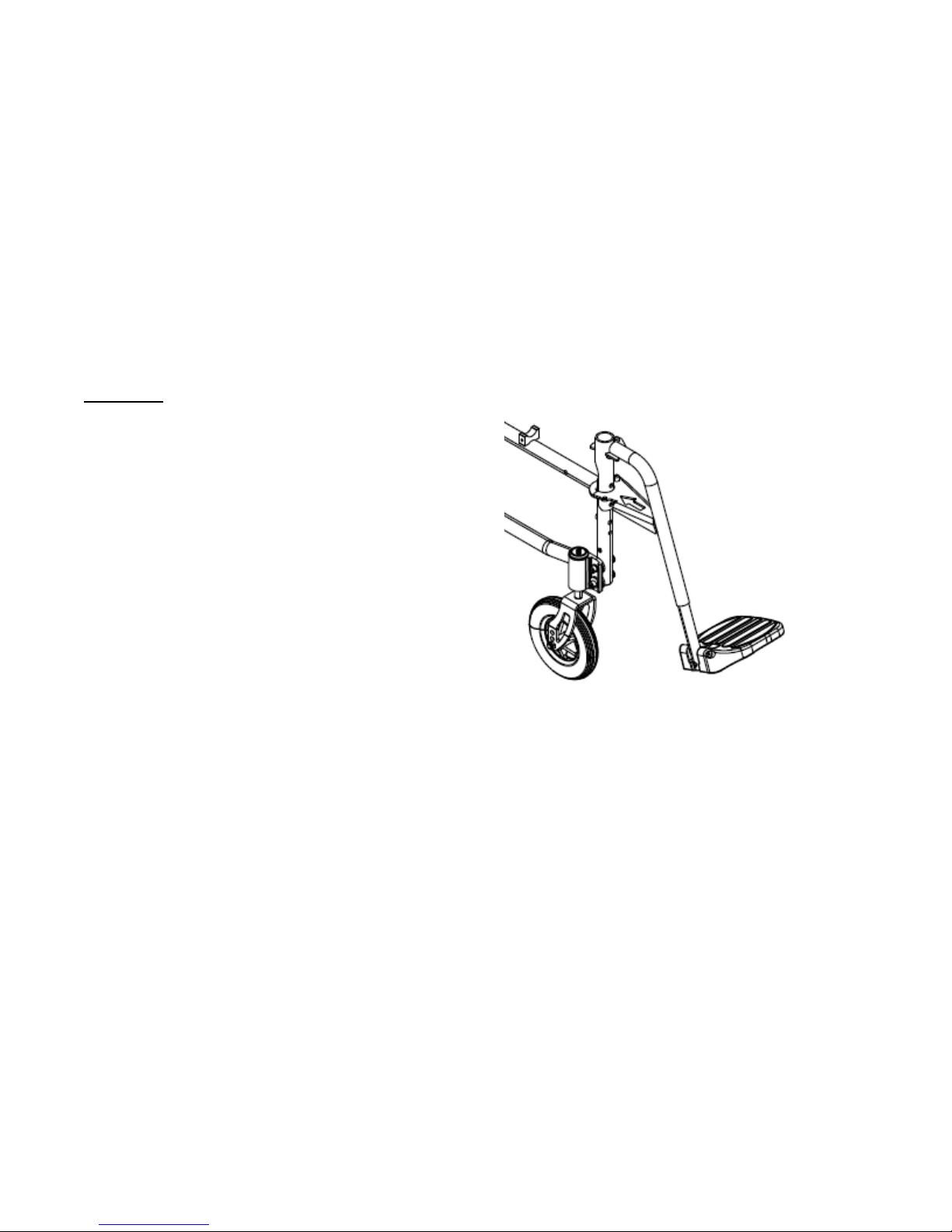
2 FRONT RIGGINGS
QSF: 390 – UM 1024404 REV03 08/20/13 12 Stellato
Removing:
1. Pull the front rigging release lever
outward.Rotate swingaway front rigging
assembly outward.
2. Lift the swingaway front rigging assembly off
the hinge pins.
Figure 2: Pin Stlye Leg Rest
Page 13
3 FOOT PLATE HEIGHT ADJUSTMENT
QSF: 390 – UM 1024404 REV03 08/20/13 13 Stellato
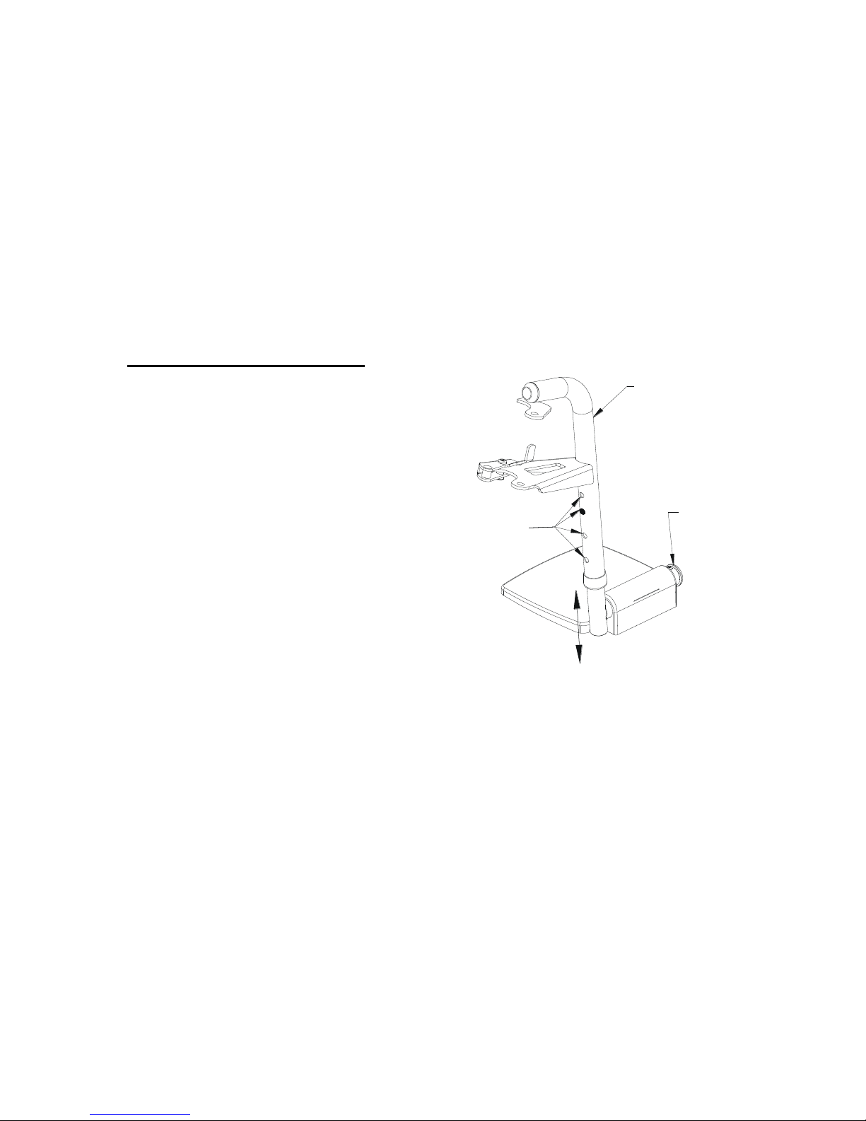
3 Foot Plate Height Adjustment
Note: This procedure applies to the swingaway front
riggings and swingaway elevating legrest.
1. Remove the front rigging assembly. Refer to
INSTALLING/REMOVING THE FRONT RIGGING in
this section of the manual.
2. Remove footrest bracket bolt. Slide footrest
extension tube up or down to desired height.
3. Re-tighten bolt.
FRONT RIGGING
SUPPORT
FOOTPLATE ASS'Y
ADJUSTMENT
HOLES
Figure 3: Height Adjustable FootPlate
Page 14
4 ELEVATING LEG REST OPERATION
QSF: 390 – UM 1024404 REV03 08/20/13 14 Stellato
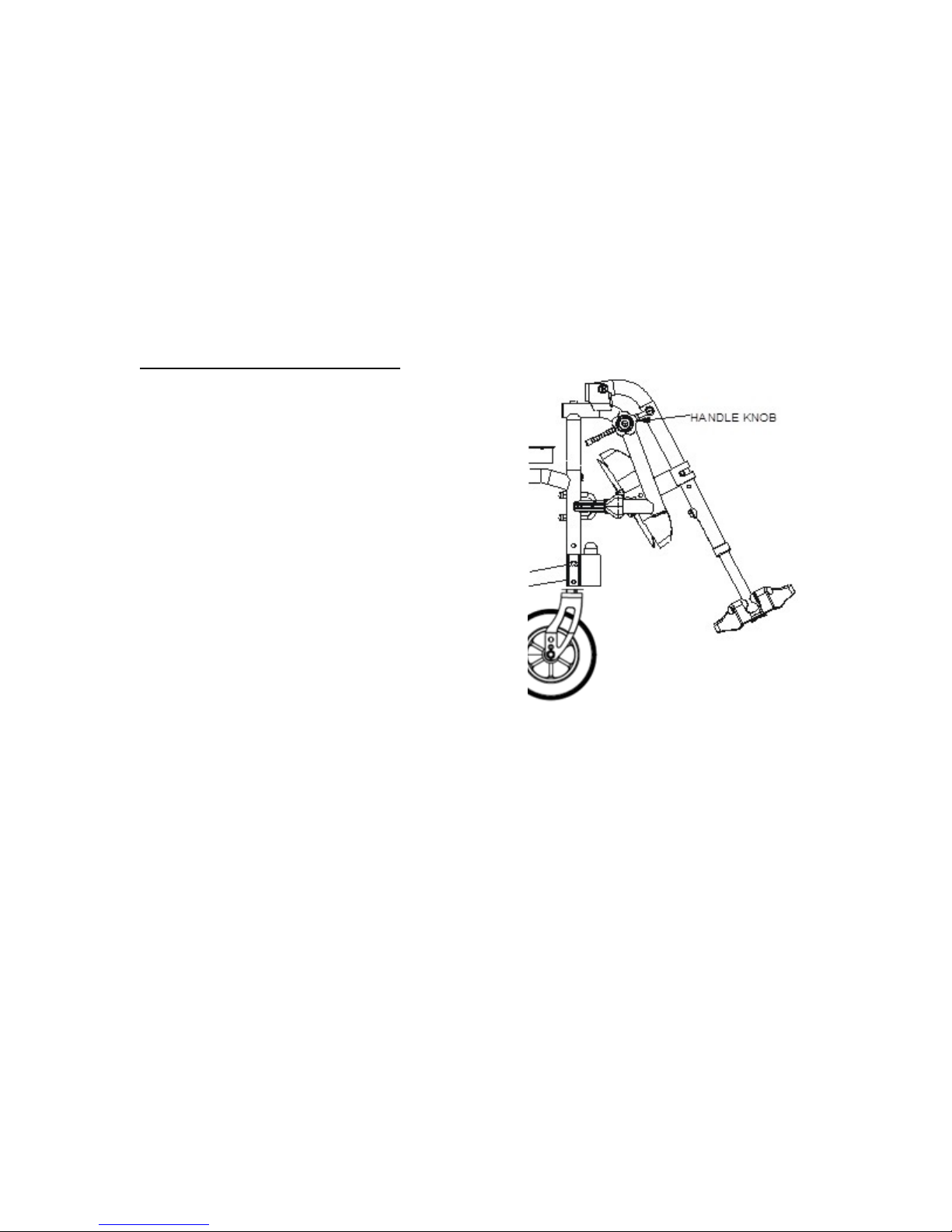
4 Elevating Leg Rest Operation
Instructions: Raising/Lowering the Elevating Leg rest
1. To adjust the angle of the elevating leg rest, turn
the handle knob counter-clockwise to disengage
from the index rod.
2. Lift the leg rest to the desired angle.
3. Re-tighten the handle knob such that the leg rest
arm remains firmly in position.
4. Swing inwards until the latch engages and locks
into the “U – Bolt”.
Figure 4: Elevating Leg Rest
Page 15
5 ARMS
QSF: 390 – UM 1024404 REV03 08/20/13 15 Stellato
5 Arms
WARNING
After ANY adjustments, repair or service and BEFORE use,
make sure all attaching hardware is tightened securely –
otherwise injury or damage may occur.
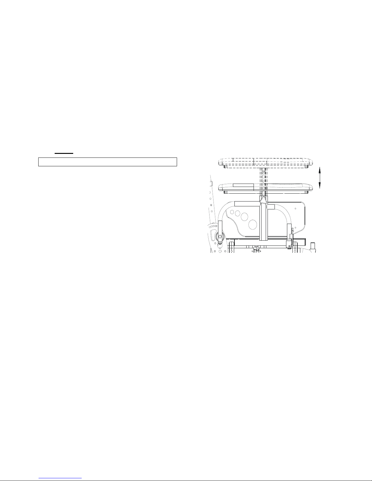
Arm Height Adjustment; Height Adjustable Arm Rest
1. Loosen knob.
2. Lift armrest until desired position is acquired
(ranges from 9 ½” – 14” in ½” increments).
3. Re-tighten knob.
Figure 5: Height Adjustment
Page 16
6 FLIP UP ARM RESTS
QSF: 390 – UM 1024404 REV03 08/20/13 16 Stellato
6 Flip up Arm Rests
After ANY adjustments, repair or service and BEFORE use,
make sure all attaching hardware is tightened securely –
otherwise injury or damage may occur.
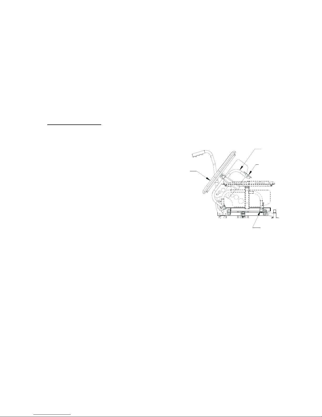
Arm Height Adjustment; Height Adjustable Arm Rest
4. Loosen knob.
5. Lift armrest until desired position is acquired
(ranges from 9 ½” – 14” in ½” increments).
6. Re-tighten knob.
ARMREST
RELEASE
LEVER
ARMREST
SOCKET
SWING
BACK
ARM
FRONT
Figure 6: Engaging Flip Up Arm Rest
Page 17
7 REPLACING UPHOLSTERY
QSF: 390 – UM 1024404 REV03 08/20/13 17 Stellato
7 Replacing Upholstery
WARNING
After ANY adjustments, repair or service and BEFORE use,
make sure all attaching hardware is tightened securely –
otherwise injury or damage may occur.
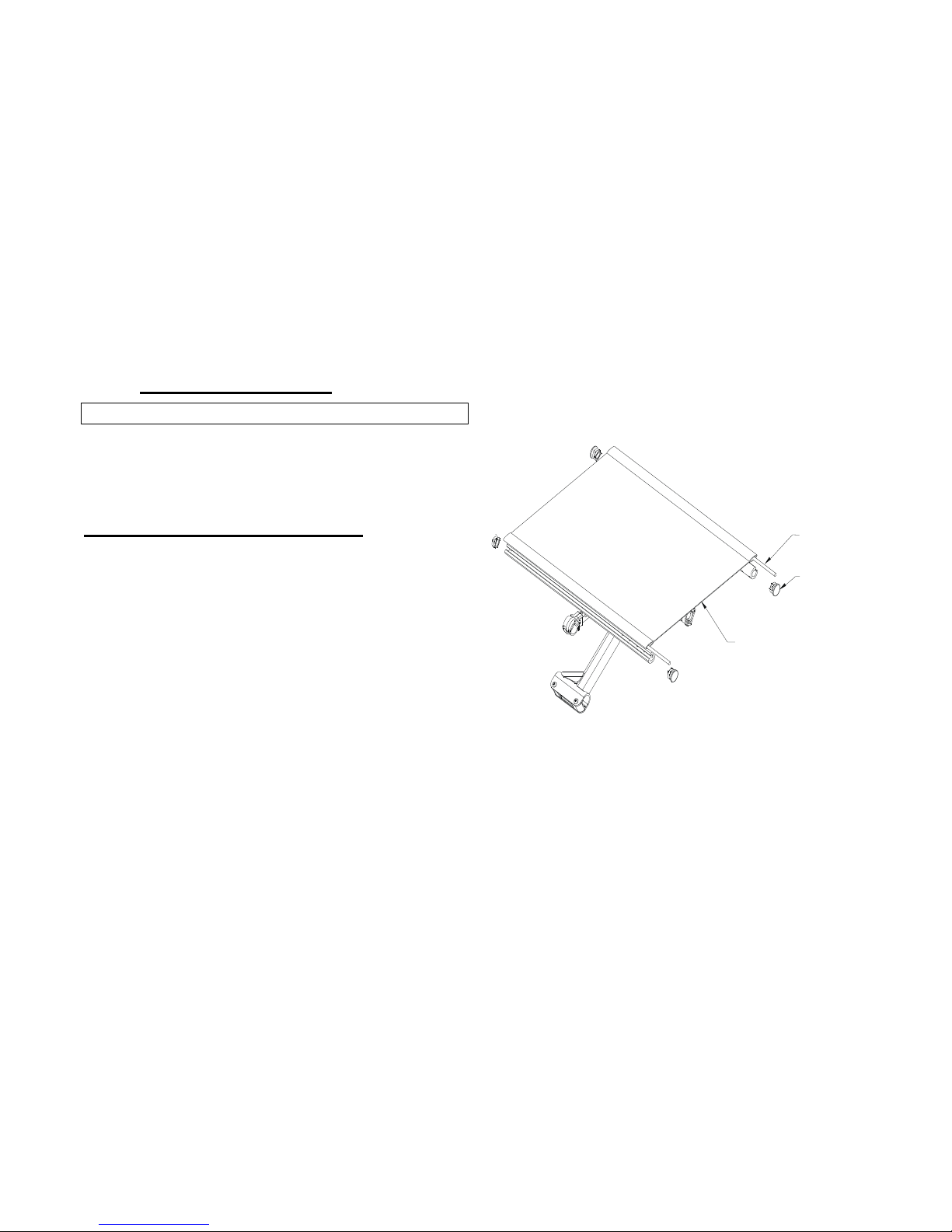
REPLACING THE SEAT UPHOLSTERY
1. Remove the front universal plugs that retain the
existing insert rod to the wheelchair seat rail.
2. Remove the existing seat upholstery from the seat
rail.
3. Install NEW seat upholstery by reversing steps 1
and 2.
SEAT UPHOLSTERY
INSERT ROD
PLUG UNIVERSAL
Figure 7: Seat Upholstery
Page 18
7 REPLACING UPHOLSTERY
QSF: 390 – UM 1024404 REV03 08/20/13 18 Stellato
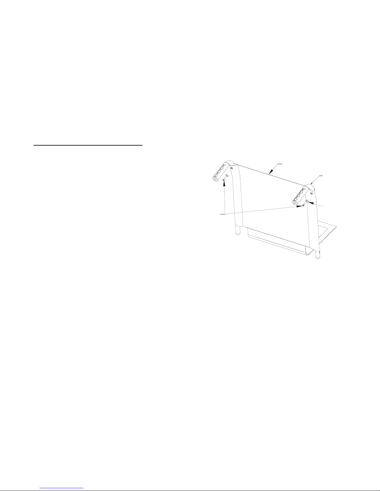
REPLACING THE BACK UPHOSTERY
Slip on Back Upholstery
1. Remove the two (2) mounting screws and washers
that secure the existing back upholstery to the back
canes.
2. Pull the loose back cane out of the existing back
upholstery.
3. Pull the existing back upholstery up and over the
mounted back cane.
4. Install the NEW back upholstery over the mounted
back cane.
5. Slide the loose back cane through the NEW back
upholstery.
6. Secure the back cane to the wheelchair frame with
the two (2) allen screws and locknuts.
7. Secure the NEW back upholstery to the back canes
with the existing mounting screws and washers.
BACK CANE
BACK UPHOLSTERY
MOUNTING SCREWS
WASHER
Figure 8: Back Slide on Upholstery
Page 19

8 REAR WHEEL ADJUSTMENTS
QSF: 390 – UM 1024404 REV03 08/20/13 19 Stellato
8 Rear Wheel Adjustments
WARNING
After ANY adjustments, repair or service and BEFORE use,
make sure all attaching hardware is tightened securely –
otherwise injury or damage may occur.
WARNING
If changing the size of the rear wheel or a change in the
seat-to-floor height is desired, this procedure MUST be
performed by a qualified technician.
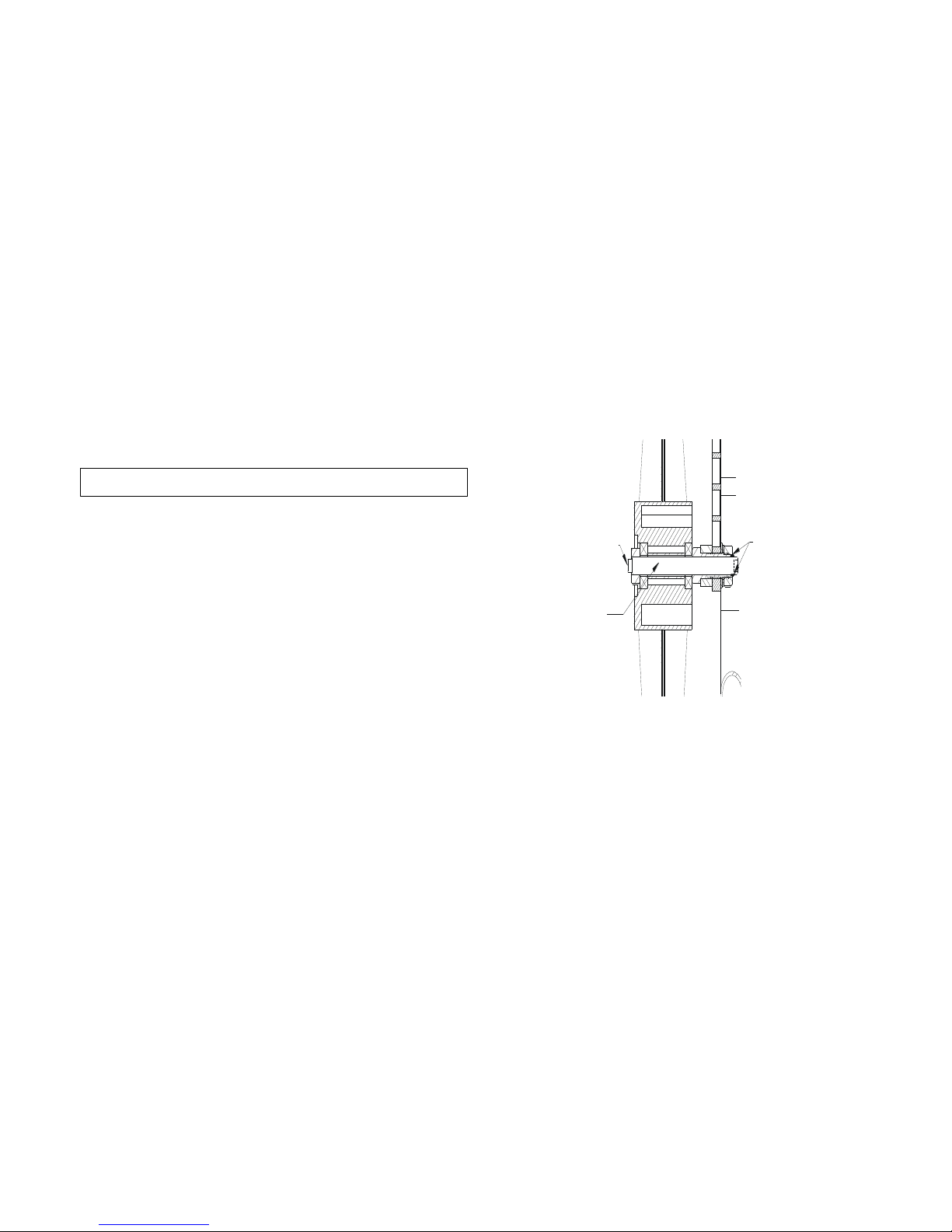
QUICK-RELEASE AXLES
1. Push in the detent pin of the quick-release axle
(with wheel) and pull the axle out through the
opening in the center of the rear wheel and axle
spacer.
2. Push in the detent pin of the quick-release axle
Figure 9: Rear Wheel Installation
QUICK-RELEASE AXLE
REAR WHEEL
AXLE SPACER
AXLE MOUNTING
PLATE-front position
REAR AXLE
THREADED
BUSHING
WHEELCHAIR
FRAME
AXLE MOUNTING
PLATE-back position
Page 20
8 REAR WHEEL ADJUSTMENTS
QSF: 390 – UM 1024404 REV03 08/20/13 20 Stellato
3. Repeats steps 1 & 2 for the opposite rear wheel.
4. To reinstall the rear wheel onto the wheelchair,
reverse steps 1 to 3.
WARNING
Make sure the detent pin and locking pins of the quickrelease axle are fully released BEFORE operating the
wheelchair.
The locking pins MUST be protruding past the inside of the
rear wheel axle bushing for a positive lock.
Keep locking pins clean.
Future Mobility Healthcare Inc. recommends inserting
quick-release axles with the detent pin to the inside of the
wheelchair to prevent accidental release during contact
activities.
DETENT PIN
LOCKING PIN
QUICK-RELEASE
AXLE
OUTSIDE OF
WHEELCHAIR
INSIDE OF
WHEELCHAIR
Figure 10: Locking Pin and Detent Pin
Page 21
9 UNFOLDING AND FOLDING THE WHEEL CHAIR
QSF: 390 – UM 1024404 REV03 08/20/13 21 Stellato
9 Unfolding and Folding the Wheel Chair
WARNING
1. Keep hands and fingers clear of moving parts to
avoid injury. DO NOT sit or transfer into the
wheelchair unless it is fully open and the seat
frame rails are fully seated into the side frame Hblocks.
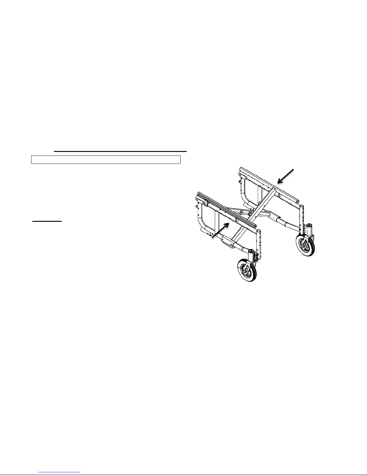
Unfolding:
2. Open the wheelchair by grasping the armrest of the
wheelchair closest to you
3. Tilt the wheelchair towards you (raising the
opposite wheel and caster off the ground/floor).
4. Push downward on the TOP of the seat rail closest
until the wheelchair is fully open and locked into Hblocks.
5. Engage both wheel locks, open the footrest/legrest
for clearance and transfer into the wheelchair.
6. Swing footrest/legrest in locked position to the
7. For folding the chair follow the above directions in
reverse.
Figure 11: Folding and Unfolding Chair: push or pull to fold and
unfold chair
Page 22
10 FRONT CASTERS
QSF: 390 – UM 1024404 REV03 08/20/13 22 Stellato
10 Front Casters
WARNING
After ANY adjustments, repair or service and BEFORE use,
make sure all attaching hardware is tightened securely –
otherwise injury or damage may occur.
INSTALLING/REPLACING FRONT CASTERS AND
FORKS
Note: This procedure can be performed if replacing the
exact same size front caster.
1. Remove dust cover.
2. Remove the locknut that secures the fork to the
caster headtube.
3. Drop the front caster and fork out of the caster
headtube.
4. Slide in the new six/eight inch front caster and fork.
5. Reassemble by reversing STEPS 1 to 3.
6. Repeat STEPS 1 to 5 for the opposite front caster.
7. To properly tighten caster journal system and
guard against flutter, perform the following check:
Figure 12: Fork
Page 23

10 FRONT CASTERS
QSF: 390 – UM 1024404 REV03 08/20/13 23 Stellato
a. Tip back of wheelchair to floor
b. Pivot both forks and casters to top of their arc
simultaneously.
c. Let casters drop to bottom of arc (wheels
should swing once to one-side, then
immediately rest in a straight downward
position).
d. Adjust locknuts according to freedom of caster
swing.
8. Test wheelchair for maneuverability.
9. Readjust locknuts if necessary and repeat STEPS 7
to 8 until correct.
10. Snap dust cover over the locknut and stem.
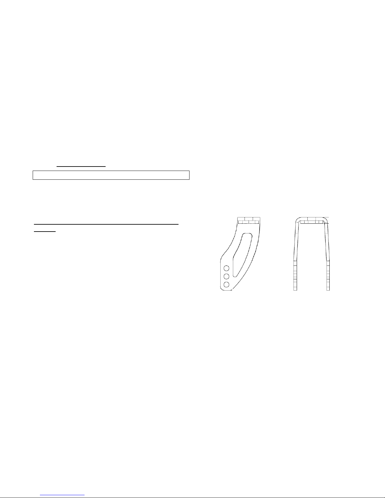
Adjusting Front Caster Angle
1. Remove bolt and loosen locknut.
2. Adjust cam plate for angle.
3. Reinsert bolt, tighten locknut.
Figure 13: Plate Adjustable Angle
Position 1
Position 2
Position 3
0 degrees
4 degrees
7 degrees
Page 24
11 ANTI-TIPPERS
QSF: 390 – UM 1024404 REV03 08/20/13 24 Stellato
11 Anti-Tippers
WARNING
After ANY adjustments, repair or service and BEFORE use,
make sure all attaching hardware is tightened securely –
otherwise injury or damage may occur.
Installing/Adjusting The Anti-Tippers
WARNING
Anti-tippers are specific to the different seat-to floor angles
and/or seat-to-floor heights. Refer to the chart in this
section of the manual for correct usage and adjustment. If
these requirements CANNOT be achieved, DO NOT us the
wheelchair. Contact a qualified technician. If changing the
seat-to-floor height with or without a change to seat-tofloor angle, the correct anti-tippers MUST be used to
maintain a 1 ½ “to 2” ground clearance.
Seat-to-floor angle of 0 degrees to 3 degrees: if so
equipped, anti-tippers MUST be attached at all times. In as
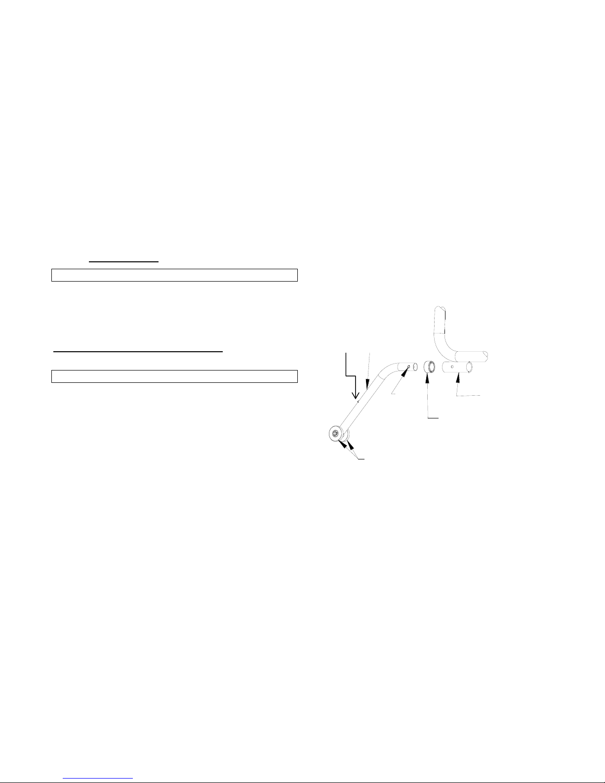
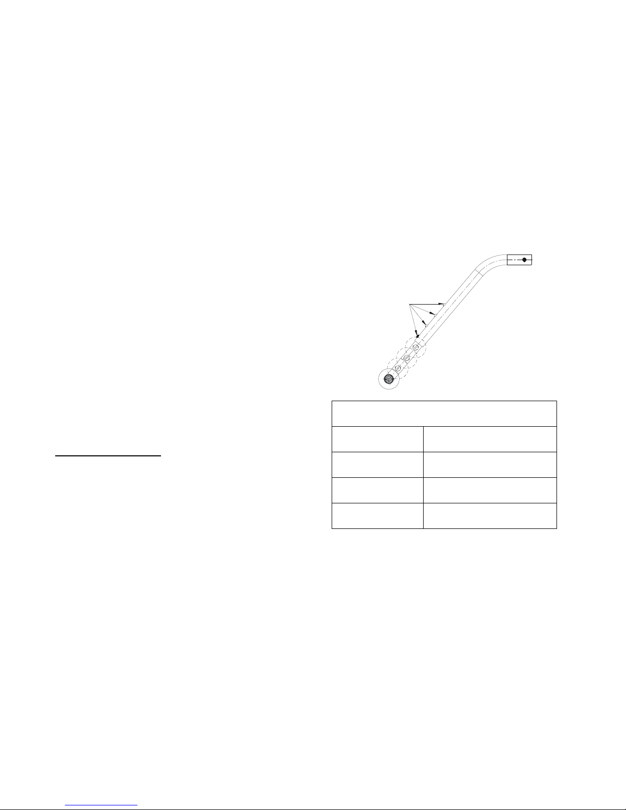
Figure 14: Anti Tippers
FRAME TUBING
GLIDE BUSHING
RELEASE
BUTTONS
ANTI-TIPPER
ANTI-TIPPER WHEELS
Push button
Page 25
11 ANTI-TIPPERS
QSF: 390 – UM 1024404 REV03 08/20/13 25 Stellato
much as the anti-tippers are an option for 0 degrees or 3
degrees on this wheelchair (you may order with or without
the anti-tippers), Future Mobility Healthcare Inc. strongly
recommends ordering the anti-tippers as a safeguard for the
wheelchair user.
Seat-to-floor angle of 6 degrees: if changing the seat-tofloor angle to 6 degrees, anti-tippers MUST be ordered and
installed.
Anti-tippers MUST be fully engaged and release buttons
fully protruding out of adjustment holes.
Ensure both anti-tippers are adjusted to the same mounting
hole.
Installing Anti-Tippers
Press the release buttons IN and insert the anti-tippers with
the anti-tipper wheels pointing toward the ground/floor into
the rear frame tubing until the bottom release button locks
in place.
Measure the distance between the bottom of the antitipper wheels and the ground/floor.
RELEASE BUTTON
Figure 15: Anti Tippers Adjustment Criteria
STELLATO
Seat to Floor
Height
Anti-Tippers
13.25” – 14.5”
Small Anti-tip assembly
(1003816)
15” – 16.5”
Medium Anti-tip assembly
(1006351)
17” – 19.0”
Large Anti-tip assembly
(1003815)
Page 26

11 ANTI-TIPPERS
QSF: 390 – UM 1024404 REV03 08/20/13 26 Stellato
If the distance between the bottom of the anti-tipper
wheels and the ground/floor is not 1 ½ “ to 2”, adjust the
anti-tippers. Refer to ADJUSTING THE ANTI-TIPPERS in this
section of the manual.
Note: A 1 ½ “to 2” clearance between the bottom of the
anti-tipper wheels and the ground/floor MUST be
maintained at all times.
ADJUSTING THE ANTI-TIPPERS
1. Press the release buttons on the wheeled portion of the
anti-tipper and slide it up or down to achieve the 1 ½
“to 2” clearance.
2. Check to make sure that the release buttons are fully
engaged in adjustment holes.
NOTE: Refer to the following chart to ensure the correct
anti-tipper is installed in the wheelchair. Seat-to-floor
heights are approximate depending on front caster size
and type. Also note the anti-tippers come in various
bends for various height ratios.
Page 27
12 WHEEL LOCKS OPERATION
QSF: 390 – UM 1024404 REV03 08/20/13 27 Stellato
12 Wheel Locks Operation
WARNING
DO NOT attempt to stop a moving wheelchair with the
wheel locks. WHEEL LOCKS ARE NOT BRAKES – otherwise
injury or damage may occur.
1. Ensure the wheelchair is not moving before
engaging the wheel locks.
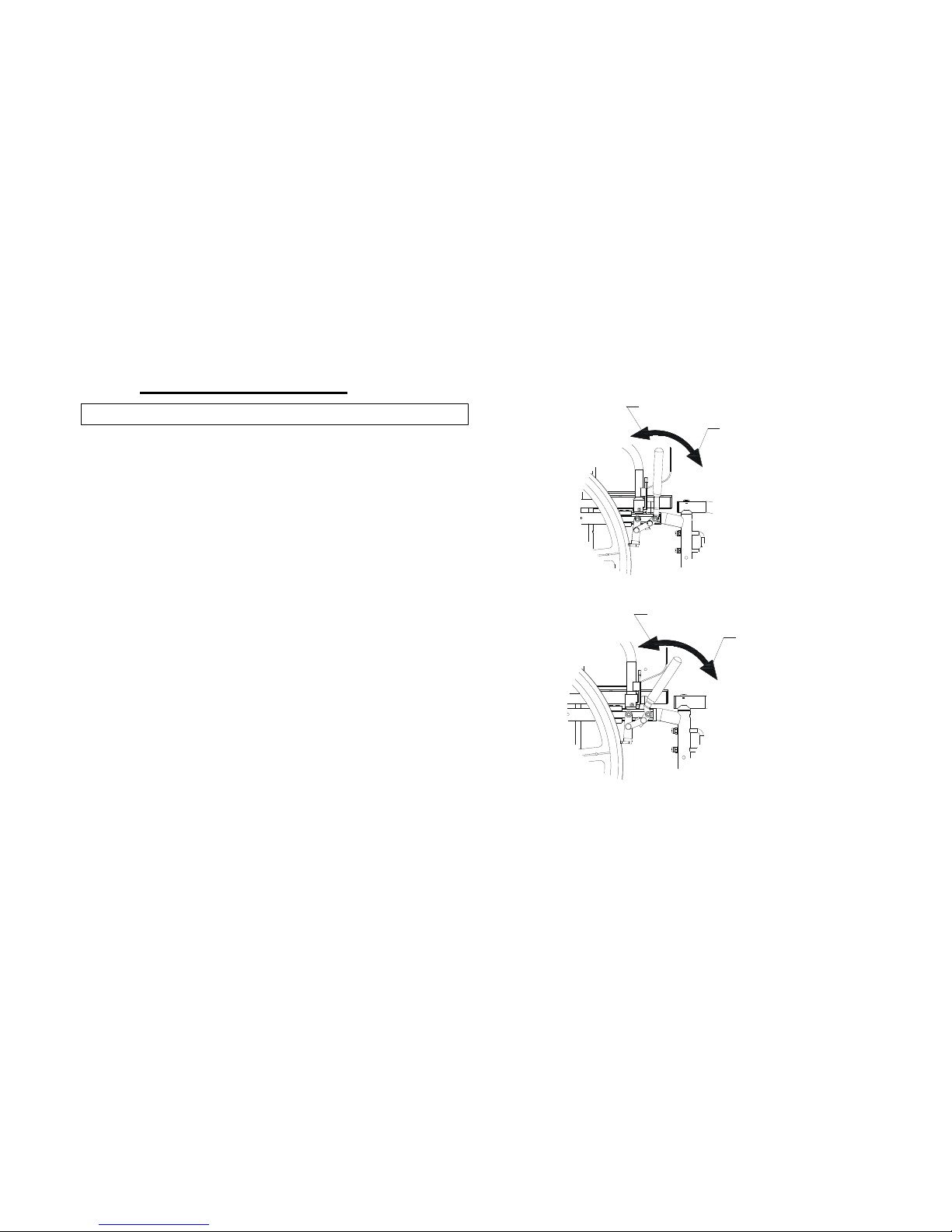
2. Perform one (1) of the following:
a. Push-to-Lock – to engage, push the wheel
lock handle forward
b. Pull-to-Lock – to engage, pull the wheel
lock handle backward
3. Disengage the wheel locks by reversing STEP 2.
LOCKED
POSITION
UNLOCKED
POSITION
Figure 16: Pull to Lock
LOCKED
POSITION
UNLOCKED
POSITION
Figure 17: Push to Lock
Page 28

12 WHEEL LOCKS OPERATION
QSF: 390 – UM 1024404 REV03 08/20/13 28 Stellato
ADJUSTING THE PATIENT OPERATED WHEEL
LOCKS –
1. Disengage the wheel locks.
2. CLAMP-ON Wheel Locks – loosen the two (2)
socket screws that secure the wheel lock to the
wheelchair frame.
3. Reposition the wheel lock so that when engaged,
the wheel lock shoe embeds the tire 1/8” (3/16”
for pneumatic tires) and HOLDS the occupied
wheelchair in place when pushed.
4. Securely tighten the bolt and locknut or socket
screws securing the wheel lock to the wheelchair
frame.
5. Engage the wheel lock.
6. Measure the distance the wheel lock is embedded
into the tire
7. Repeat STEPS 1 to 6 until the wheel lock shoe
embeds the tire and HOLDS the occupied
wheelchair in place when pushed.
8. Engage both wheel locks and ensure the occupied
wheelchair is held in place when pushed.
SOCKET
SCREWS
WHEEL LOCK
CLAMP
WHEELCHAIR
FRAME
Figure 18: Positioning the Wheel Locks
Page 29

13 OPERATING INFORMATION
QSF: 390 – UM 1024404 REV03 08/20/13 29 Stellato
13 Operating Information
Unless otherwise noted, all service and adjustment should be performed while the wheelchair is unoccupied.
To determine and establish your particular safety limits, practice bending, reaching and transferring activities in several
combinations in the presence of a qualified healthcare professional BEFORE attempting active use of the wheelchair.
Always verify that hand grips on the rear cane are secure PRIOR to use when an attendant is used to propel or lift the chair.
Check for any signs of looseness or deterioration and if found, contact a qualified technician. DO NOT attempt to move the
wheelchair by hand grips if they are broken.
DO NOT sit or transfer into the wheelchair unless it is fully open and the seat frame rails are fully seated into the
side frame H-blocks.
DO NOT TRAVERSE, CLIMB or GO DOWN ramps or slopes greater than 9 degrees
DO NOT attempt to move up or down an incline with a water, ice or oil film
DO NOT operate on roads, streets or highways
DO NOT attempt to ride over curbs or obstacles. Doing so may cause your wheelchair to tip over and cause bodily
harm to you or damage to the wheelchair.
DO NOT attempt to reach objects if you have to move forward in the seat.
DO NOT attempt to reach objects if you have to pick them up from the floor by reaching down between your
knees.
WARNING
Page 30

13 OPERATING INFORMATION
QSF: 390 – UM 1024404 REV03 08/20/13 30 Stellato
DO NOT lean over the top of the back upholstery. This will change your center of gravity and may cause you to tip
over.
DO NOT shift your weight or sitting position toward direction you are reaching as the wheelchair may tip over.
WHEEL LOCKS ARE NOT BRAKES. DO NOT attempt to stop a moving wheelchair with wheel locks.
DO NOT tip the wheelchair without assistance.
DO NOT use an escalator to move a wheelchair between floors. Serious bodily injury may occur.
Before attempting to transfer in and out of the wheelchair, every precaution should be taken to reduce the gap
distance. Turn both casters parallel to the object you are transferring onto. When transferring to and from the
wheelchair, ALWAYS ENGAGE BOTH WHEEL LOCKS.
DO NOT use parts, accessories or adapters other than those authorized by Future Mobility Healthcare Inc.
Otherwise, the warranty is void.
DO NOT attempt to lift the wheelchair by any removable (detachable) part. Lifting by means of any removable
(detachable) parts of a wheelchair may result in injury to the user and/or assistant or damage to the wheelchair.
DO NOT stand on the frame of the wheelchair.
DO NOT use the footplate as a platform. When getting in or out of the wheelchair, make sure that the footplates
are in the upward position.
Page 31

14 WEIGHT TRAINING
QSF: 390 – UM 1024404 REV03 08/20/13 31 Stellato
14 Weight Training
Future Mobility Healthcare Inc. DOES NOT recommend the use of its wheelchairs as a weight training apparatus. Future
Mobility Healthcare Inc. wheelchairs have NOT been designed or tested as a seat for any kind of weight training. If
occupant uses said wheelchair as a weight training apparatus, Future Mobility Healthcare Inc. shall NOT be liable for bodily
injury or damage to the wheelchair and the warranty is void.
WARNING
Page 32

WARRANTY
15 Warranty
This warranty is extended only to the original purchaser/user of our products.
Future Mobility Healthcare Inc. (“FMHI”) warrants its Stellato II Wheelchair parts and miscellaneous components to be free
from defects in materials and workmanship for one (1) year from the date of purchase. The frame is warranted for the
lifetime of the original purchaser/user. The upholstery is warranted for 90 days, upon normal usage by original purchaser. If
within this warranty period the product shall be proven to be defective, such product shall be repaired or replaced, at FMHI
discretion. FMHI’s sole obligation and your exclusive remedy under this warranty shall be limited to the repair and/or
replacement of the product or its parts. This warranty does not include any labour or shipping charges incurred in
replacement part installation or repair of any product.
For warranty service, please contact the dealer from whom you purchased your FMHI product. In the event you do not
receive satisfactory warranty service, please write directly to FMHI. Provide the dealer's name, address, model number,
date of purchase and indicate the nature of the defect.
DO NOT return products to FMHI without our prior consent. The defective unit or parts must be returned for warranty
inspection within thirty (30) days of the return authorization date. (FMHI will issue a return authorization number). Please
prepay all shipping charges; C.O.D. shipments will be refused.
LIMITATIONS and EXCLUSIONS: This warranty shall not apply to problems arising from normal wear or failure to adhere to
the enclosed instructions. Products subjected to negligence, accident, improper usage, maintenance or storage; or products
modified without FMHI written consent including, but not limited to: modification through the use of any unauthorized
parts or attachments; products damaged by reason or repairs made to any component without the specific consent of
FMHI, or products repaired by anyone other than a FMHI dealer. Such evaluation shall be determined by FMHI.
The foregoing warranty is exclusive and in lieu of all other expressed warranties. It shall not extend beyond the duration of
the expressed warranty provided herein and the remedy for violations of any implied warranty shall be limited to repair or
replacement of the defective product pursuant to the terms contained herein. FMHI shall not be liable for any
consequential or incidental damages whatsoever
Page 33
Page 34

Page 35

Page 36

 Loading...