

Page 1
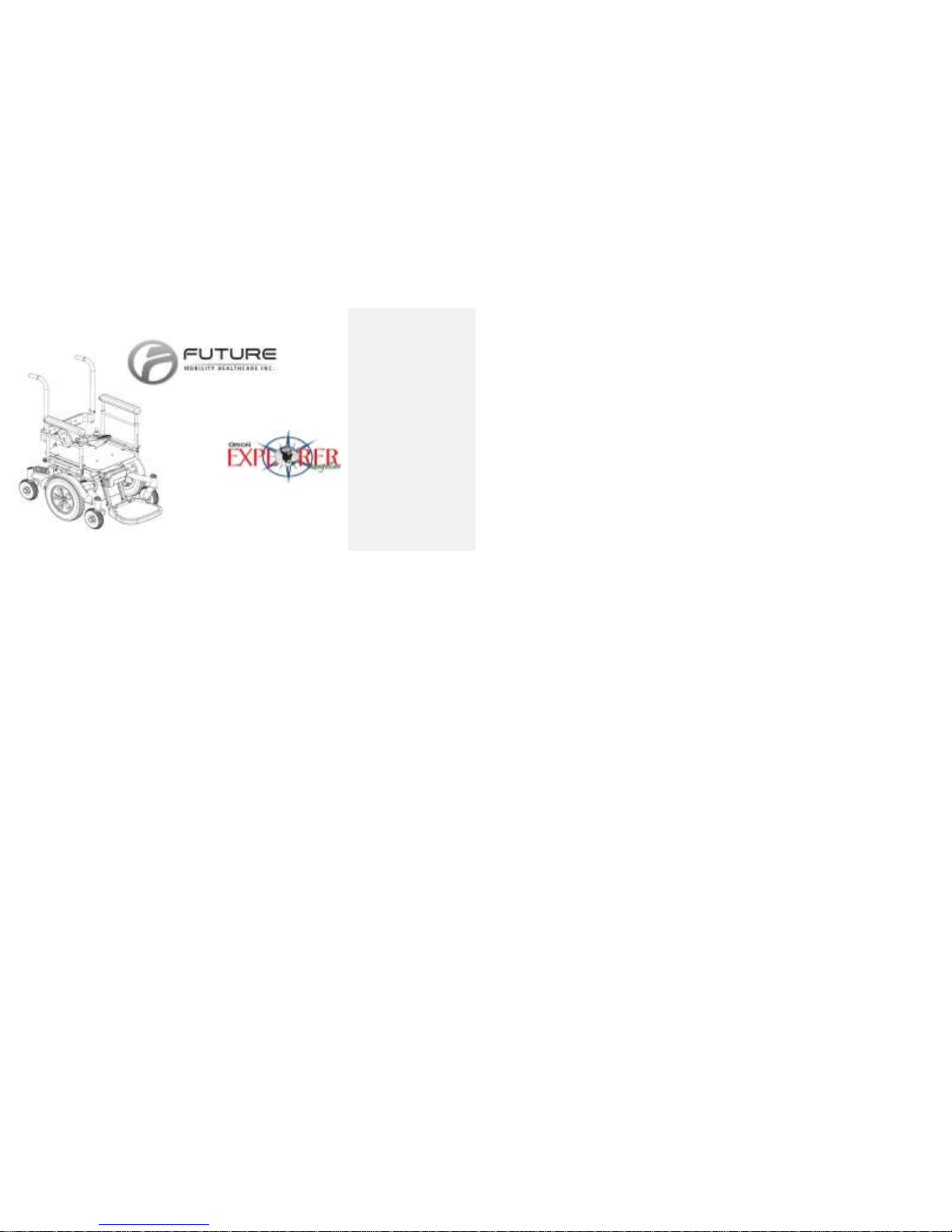
730 REV09 REV DATE: 09-02-2014
USER MANUAL
Page 2

CONTENTS
730 REV 09 DATE REV: 09/02/14 2 POWER CHAIR: EXPLORER MAGELLAN
1 General......................................................................................................................................................................................... 4
Important Safety Precautions ......................................................................................................................................................... 5
Features ............................................................................................................................................................................................ 8
Maintenance and Troubleshooting ................................................................................................................................................ 9
Troubleshooting ............................................................................................................................................................................. 15
2 Electrical and Magnetic Interference ...................................................................................................................................... 18
Electro Magnetic Interference from Radio Wave Sources ......................................................................................................... 18
Power Wheel Chair Electromagnetic Interference ..................................................................................................................... 20
4 Movement and Controls ........................................................................................................................................................... 22
5 Handling ..................................................................................................................................................................................... 27
6 Batteries ..................................................................................................................................................................................... 34
Battery ............................................................................................................................................................................................ 34
Battery Charging ............................................................................................................................................................................ 36
Battery Installation and Removal ................................................................................................................................................. 38
7 Chair Adjustments ..................................................................................................................................................................... 44
Concepts’ Arm Pad Position (Fore/Aft & Lateral) ........................................................................................................................ 44
2 Point Traditional Arm Adjustments ........................................................................................................................................... 45
Back Adjustments .......................................................................................................................................................................... 46
Page 3

CONTENTS
730 REV 09 DATE REV: 09/02/14 3 POWER CHAIR: EXPLORER MAGELLAN
Seat Adjustments ........................................................................................................................................................................... 51
Free Wheel ..................................................................................................................................................................................... 56
Front Riggings ................................................................................................................................................................................ 59
Anchor Brackets ............................................................................................................................................................................. 63
8 Cleaning Instructions ................................................................................................................................................................ 64
9 Limited warranty ....................................................................................................................................................................... 65
Limitations and Exclusions. ........................................................................................................................................................... 66
Page 4

1 GENERAL
730 REV 09 DATE REV: 09/02/14 4 POWER CHAIR: EXPLORER MAGELLAN
1 General
NOTICE: Information contained within this document is subject to
change without notice.
WARNING: DO NOT install this equipment without first reading and
understanding this instruction booklet. If you are unable to
understand these instructions, contact a healthcare professional,
dealer or technical personnel before attempting to install this
equipment - otherwise, injury or damage may occur.
NOTE: Check all parts for shipping damages before using. In case of
damage, DO NOT use the equipment.
Contact the Equipment Supplier for further instructions.
Page 5

1 GENERAL
730 REV 09 DATE REV: 09/02/14 5 POWER CHAIR: EXPLORER MAGELLAN
Important Safety Precautions
Your safety is very important. A power wheelchair can be dangerous if used improperly or under the wrong
conditions. Please always follow the safety precautions listed below.
Safety requires constant attention and it is very important to learn and always use safe methods of performing
basic daily activities. Always consult health care professionals to determine those methods most suitable for your
individual abilities.
Page 6
1 GENERAL
730 REV 09 DATE REV: 09/02/14 6 POWER CHAIR: EXPLORER MAGELLAN
Warning! The maximum user weight for this wheelchair is 136 kg (300 lbs). Do not exceed this
maximum value.
Warning! Do not operate this wheelchair on public roads or highways, hilly or rough terrain, or
wet or icy surfaces.
Warning! Do not attempt to go up, go down, or traverse ramps of more than 9 degrees (15%
grade, or one foot rise in six).
Warning! THIS WHEELCHAIR HAS NOT BEEN APPROVED AS A SEAT IN A MOTORVEHICLE.
Always transfer to an approved vehicle seat, and use the provided motor vehicle
restraints when in a motor vehicle.
Comment [SS1]:
Page 7

1 GENERAL
730 REV 09 DATE REV: 09/02/14 7 POWER CHAIR: EXPLORER MAGELLAN
Warning! Always turn the wheelchair power OFF before transferring. This ensures that the
incidental contact with the joystick during transfers does not move the wheelchair.
Warning! Do not stand or step on the footboard or footrests when transferring to or from the
wheelchair as this could cause the wheelchair to shift or tip.
Warning! If you are reaching for an object, do not shift your weight or seat position in the
direction you are reaching as this could cause the wheelchair to shift or tip.
Warning! Do not tow or “piggyback” passengers or heavy packages. This will compromise the
safety and performance of Explorer Magellan.
Warning! Controller programs or settings should only be made by healthcare professionals or
by persons fully conversant with this process, the driver’s capabilities, and the
environment in which Explorer Magellan is to be used.
Warning! Do not connect accessories to the batteries. This will decrease driving range and
shorten battery life. Do not connect ANYTHING to a single battery. This will cause
premature battery failure.
Warning! Only use Future Mobility Healthcare authorized parts and accessories.
Page 8

1 GENERAL
730 REV 09 DATE REV: 09/02/14 8 POWER CHAIR: EXPLORER MAGELLAN
Features
FEATURES
SPECIFICATIONS
Full suspension base with front and rear
shocks
Designed for two – 12 volt 22NF batteries
PGDT VR2 controller with joystick and 4A
charger on board
Standard seating system consisting of: solid
seatpan, Orion back and Prism Ideal cushion
2 pole right angle motors
Seat width can increase from 16” to 20” or 20”
to 24” as well as seat depth can increase from
17” to 20” without the need of changing frame
members.
Arm heights: 9-3/4” – 12-3/4” (adjustable)
Angle adjustable back (87° to 110°)
70/80 degree pinstyle front riggings or one
piece footboard
Fixed headrest with foam pad Composite
footplates
Heel loops front and rear transit hooks
(optional)
Range per charge: 13.4 miles (21.6km)
Shroud colors: black, blue, green, red
Seat Width: 16” – 24”
Seat Depth: 17” – 20”
Seat Width (including joystick): 22-1/4” – 301/4”
Base Width: 24-1/4”
Length with Footboard in Use: 37”
Length with Swingaway Footrests in Use: 40”
to 45” (3)
Height: 40” to 45”(3)
Seat to Floor: 17” to 19”
Weight (with batteries): 208lbs
Weight (without batteries): 132 lbs
Drive Wheels: 12-1/2” x 2-1/4” pneumatic or
airless
Casters: 6” x 2” semi-pneumatic
Arm Style: Full length adjustable height flip
back (vinyl or multi position foam)
Front Riggings: One piece flip-up footboard, pin
style, swingaway or elevating legrests
Weight Capacity: 300lbs (136kgs)
Maximum Speed: 4.3mph (7km/h)
Ground Clearance: 3” (7.6cm)
Turning Radius: 20.3” (52cm)
Page 9
1 GENERAL
730 REV 09 DATE REV: 09/02/14 9 POWER CHAIR: EXPLORER MAGELLAN
Frame Colours: Black
Maintenance and Troubleshooting
Maintenance.
Explorer Magellan has been designed as a simple, robust product and if you are able to take good care of it, it will
reward you with many years of dependable performance. There is not a separate service manual for Explorer
Magellan. If you feel any part of your power chair is not performing as it should, please contact your Future
Mobility Healthcare dealer as soon as possible. They will quickly be able to diagnose the problem and perform
any service or repairs necessary.
Do-it-yourself maintenance.
If you have a mechanical aptitude and a few simple tools you will probably be able to do many of the scheduled
maintenance tasks yourself. Please refer to the schedule below and if any of the tasks are unclear please contact
your Future Mobility Healthcare dealer for assistance.
Task
Daily
Weekly
Monthly
3 months
6 months
Charge batteries
*
Check joystick
*
Check tire pressure & wear
*
Clean base frame
*
Page 10
1 GENERAL
730 REV 09 DATE REV: 09/02/14 10 POWER CHAIR: EXPLORER MAGELLAN
Check arms *
Clean & check upholstery
*
Check cables and connectors.
*
Clean batteries and terminals
*
Check caster socket rotation
*
Inspect motor brushes
*
Charge batteries.
Charge the batteries daily. This will greatly increase their life and also prevent a number of potential problems that
could result in the poor performance of your power chair. The charger is designed to prevent battery overcharging. No tools required.
Check joystick.
Check the operation of the integrated joystick/control module every week. With the power turned OFF check that
the joystick is not bent or damaged, and that it returns to the neutral (central) position when it is released. Check
the rubber protective boot around the joystick for damage or tears. A visual check is sufficient. Please handle the
boot as little as possible. There are no serviceable parts in the integrated joystick/control module. If you are
experiencing any problems with this component, it is very important to contact your dealer. No tools required.
Page 11

1 GENERAL
730 REV 09 DATE REV: 09/02/14 11 POWER CHAIR: EXPLORER MAGELLAN
Check tire pressures and wear.
Please examine both the drive wheel tires and caster wheel tires on your Explorer Magellan every month. Both
airless and pneumatic tires should be checked for wear and to confirm mechanical integrity. Pneumatic tires
should be checked for proper pressure (30 psi is recommended). A standard automobile or bicycle air-pressure
gauge may be used. Never exceed the pressure specified on the sidewall of the tire. When inflating tires, use a
Page 12
1 GENERAL
730 REV 09 DATE REV: 09/02/14 12 POWER CHAIR: EXPLORER MAGELLAN
hand or foot-powered pump, or a regulated air supply, and do not exceed the recommended pressure of 30 psi.
Tools required: air-pressure gauge, regulated air supply.
Clean base frame.
A soft cloth may be used to clean the base, wheels and plastic components. Keeping the base clean will prevent
the buildup of dust and moisture, which could result in poor performance or premature wear of components. The
soft cloth may be dry, or dampened with a mild soap and water solution. Do not use abrasives on your Explorer
Magellan. Tools required: soft cloth, mild soap, water.
Check arms.
Please inspect the arms for damage and for proper operation every four weeks. Ensure that the arm will lock in
each of the arm heights and that it flips back and returns to the vertical position as intended. Ensure that the arm
pad and controller mounting are secure. No tools required.
Warning! Do not over-inflate pneumatic tires. Over-inflation of tires can result in a burst tube, with a
risk of personal injury or damage to the wheelchair.
Page 13

1 GENERAL
730 REV 09 DATE REV: 09/02/14 13 POWER CHAIR: EXPLORER MAGELLAN
Check & clean upholstery.
Check upholstery at least once every month. Inspect for tears and worn areas. At the same time as this
inspection, it is recommended that the upholstery be cleaned with a mild soap and water solution. Tools required:
soft cloth, mild soap, water.
The cover is designed to protect the foam against a user's incontinence and to provide fire retardency, so the
PRISM Back's must not be used without their covers. If the cover is torn, it must be replaced.
Foam
If the PRISM Back foam becomes contaminated due to incontinence, the foam pad CAN be replaced
independently. Foam can be purchased separately by ordering through Future Mobility Healthcare Customer
Service.
Cables and connectors.
Please inspect all connectors once every three months to ensure that they are securely fastened. It is
recommended that you DO NOT disconnect the cables, just ensure that the connections are secure. No tools
required.
Clean batteries and terminals.
Clean both the batteries and their terminals every three months. This will ensure the integrity of the power
supplied to the controller. Many of the failures reported on wheelchairs can be directly related to batteries and
their connectors.
Page 14

1 GENERAL
730 REV 09 DATE REV: 09/02/14 14 POWER CHAIR: EXPLORER MAGELLAN
A wire brush or emery paper may be used to remove corrosive build-up around terminals. Caution must be used
when working with batteries. If you do not feel comfortable with these activities, contact your Future Mobility
healthcare dealer for assistance. Tools required: wire brush, emery paper, ½” wrench, protective gloves, eye
protection, and face shield.
Warning! It is important that you do not allow any tools or conductive material to directly connect the
two terminals of a battery. Do not wear watches or jewelry when working on batteries. If you
are not confident in your ability to work with batteries, ask your dealer for assistance.
Warning! Each battery weighs more than 14 kg. Be sure to use good body position and lifting
techniques when loading and unloading batteries.
Warning! Some battery components (posts, terminals, etc.) contain lead compounds. Always wash
hands after handling, or wear protective gloves. Eye protection and face shield are also
recommended when working with batteries.
Page 15

1 GENERAL
730 REV 09 DATE REV: 09/02/14 15 POWER CHAIR: EXPLORER MAGELLAN
Troubleshooting
Symptom(s)
Scenarios and Solutions
Explorer Magellan will
not turn on
1. Circuit breaker (white button) on rear battery assembly has tripped. Press
the button in to reset it, and turn the chair on again. If the circuit breaker
continues to trip, contact your dealer for assistance.
2. Not all connectors are attached properly. Check that all connectors are
properly engaged and turn the chair on again.
3. Batteries have been discharged. Charge batteries completely. Remove
charger plug from wall outlet when charging cycle is complete, stow cable,
and turn the chair on again.
Explorer Magellan will
not drive.
1. Controller shows that unit is powered, but Explorer Magellan will not drive.
When joystick is moved, motors click as parking brake disengages, but
wheels do not turn. Check the position of the freewheeling levers. In order
to control Explorer Magellan with the joystick, the free wheel levers on the
top of the fenders must point towards the rear of the wheelchair.
2. Explorer Magellan is plugged into wall outlet for charging. A safety ‘inhibit’
line is included on Explorer Magellan to stop it from driving when it is
plugged into a wall socket.
3. Controller lights are flashing. Consult controller manual for fault code
information.
Page 16

1 GENERAL
730 REV 09 DATE REV: 09/02/14 16 POWER CHAIR: EXPLORER MAGELLAN
Explorer Magellan turns
in a complete circle but
will not drive straight.
1. One of the freewheeling levers is in the position that disengages its motor.
Turn the wheelchair off. Inspect the freewheel levers on the top of the
fenders. Turn them until they both point towards the rear of the wheelchair.
Turn Explorer Magellan on and try again.
Explorer Magellan is
charging but I cannot
drive it with the joystick.
1. The battery charger is not properly connected at the front of Explorer
Magellan. Remove the fabric cover from its hook and loop mounts at the
front of Explorer Magellan.
2. If the Explorer Magellan can still drive, ensure that the connection between
the battery charger and the extension cable is secure. Try the joystick
again.
3. If the Explorer Magellan cannot still drive, please contact your dealer.
4. If the Explorer Magellan can no longer drive and the battery charger lights
indicate proper charging, the connection has been secured. It is possible
to use a tie wrap to hold the charger cable in place so that the connector
cannot loosen itself.
When reinstalling
batteries in their
compartment, the
retention plate will not
close properly.
1. Ensure that the batteries have been reinstalled in Explorer Magellan in the
correct order. The front battery should be oriented so its black connector
is near the front of Explorer Magellan, and the rear battery should be
oriented so its white circuit breaker button is facing the rear of the chair.
2. Ensure that the black connector from the front battery is routed out of the
battery compartment, and into its socket in the controller connector at the
front of Explorer Magellan. If this connector is stuck inside the battery
compartment, it can be responsible for shifting the batteries rearward, and
preventing the battery retention plate from closing properly.
3. Ensure that the cables on the red connectors from the battery lids are not
Page 17
1 GENERAL
730 REV 09 DATE REV: 09/02/14 17 POWER CHAIR: EXPLORER MAGELLAN
caught on the battery retention bushings. Clear any snags, confirm the
connections, push the batteries fully forward, and try again.
Page 18

2 MOVEMENT AND CONTROLS
730 REV 09 DATE REV: 09/02/14 18 POWER CHAIR: EXPLORER MAGELLAN
2 Electrical and Magnetic Interference
Electro Magnetic Interference from Radio Wave Sources
Power wheelchairs may be susceptible to electromagnetic interference (EMI), which is interfering electromagnetic
(EM) energy emitted from sources such as radio stations, TV stations, amateur radio (HAM) transmitters, two-way
radios, and cellular telephones. The interference (from radio wave sources) can cause a powered wheelchair to
release its brakes, move by itself, or move in unintended directions. It can also permanently damage a powered
wheelchair’s control system. The intensity of the interfering EM energy can be measured in volts per meter (V/m).
Each powered wheelchair can resist EMI up to certain intensity. This is called its ‘immunity level’. Th e higher the
immunity level, the greater the protection. At this time, current technology is capable of achieving at least a 20
V/m immunity level, which would provide useful protection from the more common sources of radiated EMI. This
powered wheelchair model as shipped, with a VR2 PG Drives Technology controller, has an immunity level of 20
V/m.
There are a number of sources of relatively intense electromagnetic fields in the everyday environment. Some of
these sources are obvious and easy to avoid. Others are not apparent and exposure is unavoidable. However, we
believe that by taking into account the warnings that follow, your risk to EMI exposure will be minimized.
The sources of radiated EMI can be broadly classified into three types:
Page 19

2 MOVEMENT AND CONTROLS
730 REV 09 DATE REV: 09/02/14 19 POWER CHAIR: EXPLORER MAGELLAN
Hand held portable transceivers (transmitters-receivers) with the antenna mounted directly on the transmitting
unit. Examples include: citizens’ band (CB) radios, “walkie-talkies”, security, fire, and police transceivers, cellular
telephones, and other personal communication devices.
NOTE: Some cellular telephones and similar devices transmit signals while they are on, even when not being
used.
Medium-range mobile transceivers are those that are used in police cars, fire trucks, ambulances, and taxis.
These usually have the antenna mounted on the outside of the vehicle.
Long-range transmitters and transceivers are those that are used in commercial broadcast transmitters (radio
and TV broadcast antenna towers) and amateur (HAM) radios.
NOTE: Other types of hand-held devices, such as cordless phones, laptop computers, AM/FM radios, TV sets,
CD players, cassette players, and small appliances, such as electric shavers and hair dryers, so far as we
know are not likely to cause EMI problems to your wheelchair.
Page 20

2 MOVEMENT AND CONTROLS
730 REV 09 DATE REV: 09/02/14 20 POWER CHAIR: EXPLORER MAGELLAN
Power Wheel Chair Electromagnetic Interference
Since EM energy rapidly becomes more intense as one moves closer to the transmitting antenna (source), the
EM fields from hand-held radio wave sources (transceivers) are of special concern. It is possible to unintentionally
bring high levels of EM energy very close to a powered wheelchair’s control system while using these devices.
This can affect powered wheelchair movement and braking. Therefore, the warnings that follow are
recommended to prevent possible interference with the control system of the powered wheelchair.
EMI Warnings
Electromagnetic interference (EMI) from sources such as radio and TV stations, amateur radio (HAM)
transmitters, two-way radios, and cellular telephones can affect powered wheelchairs. Following the warnings
listed below should reduce the chance of unintended brake release or powered wheelchair movement that could
result in serious injury.
Important Information.
1. Twenty (20) volts per meter (V/m) is a generally achievable and useful immunity level against EMI (the
higher the level the greater the protection).
2. The immunity level of this product is 20 V/m.
Page 21

2 MOVEMENT AND CONTROLS
730 REV 09 DATE REV: 09/02/14 21 POWER CHAIR: EXPLORER MAGELLAN
Warning! Do not operate hand-held transceivers (transmitters-receivers), such as citizens’
band (CB) radios, or turn on personal communication devices, such as cellular
telephones, while the powered wheelchair is turned on.
Warning! Be aware of nearby transmitters, such as radio or TV stations, and try to avoid
coming close to them.
Warning! If unintended movement or brake release occurs, turn the powered wheelchair off as
soon as it is safe to do so.
Warning! Be aware that adding accessories or components, or modifying the powered
wheelchair, may make it more susceptible to EMI (NOTE: There is no easy way to
evaluate their effect on the overall immunity of the powered wheelchair.)
Warning! Report all incidents of unintended movement or brake release to Future Mobility
Healthcare Inc., and note whether there is a source of EMI nearby.
Page 22
3 MOVEMENT AND CONTROLS
730 REV 09 DATE REV: 09/02/14 22 POWER CHAIR: EXPLORER MAGELLAN
3 Movement and Controls
Explorer Magellan is designed to provide independence in mobility. It offers a balance between comfort,
maneuverability, speed and power. Moving and maneuvering the Magellan is easy and is discussed below.
When moving or storing an unoccupied Explorer Magellan, it is sometimes useful to be able to roll the unit without
using the joystick and motors. This condition is known as ‘Freewheeling’, and is achieved by rotating mechanical
drive-release levers through 90 degrees. These levers are located on the top of each motor gearbox, at the front
of Explorer Magellan under the seat. The freewheeling levers are turned by hand.
Energy is supplied by two Group 22NF batteries, which are individually packaged and accessed from the rear of
the chair. Proper use of Explorer Magellan includes charging the batteries nightly.
The drive system consists of two independent drive motor/wheel units and a control module with a joystick. The
motors operate in both the forward and reverse directions. Motor speed and direction are both controlled by the
joystick. Moving the joystick forward (towards the front of the chair) causes the wheelchair to move forward. The
NOTE: In freewheeling mode, the motors are disengaged, the parking brakes do not operate, and
the joystick is unable to steer Explorer Magellan. For these reasons, it is clear that an occupied
Explorer Magellan should NEVER be in freewheel mode.
Page 23

3 MOVEMENT AND CONTROLS
730 REV 09 DATE REV: 09/02/14 23 POWER CHAIR: EXPLORER MAGELLAN
farther forward the joystick is moved, the faster Explorer Magellan will move. (The maximum speed possible is
approximately 7 km/h.). Moving the joystick back will cause the chair to travel in reverse. Reverse speed is always
Page 24

3 MOVEMENT AND CONTROLS
730 REV 09 DATE REV: 09/02/14 24 POWER CHAIR: EXPLORER MAGELLAN
less than forward speed. When the joystick is moved to the right, the chair will turn to the right; when the joystick
is moved to the left, the chair will turn to the left. When the joystick is returned to the center (neutral) position, (it
will do this automatically when it is released) the control system will bring the wheelchair to a smooth stop. Upon
stopping, electromechanical disc brakes will engage to prevent Explorer Magellan from rolling. This is indicated by
an audible ‘click’ from each motor. Work with your mobility device provider to ensure that speeds and controller
responses are programmed to your driving abilities and style.
User Interface.
Explorer Magellan’s controller has been designed to be both accessible and comfortable. The user has control
over power on/off, speed, direction and maximum speed limit. In addition, the user is constantly notified of the
battery charge level and, should they occur, system faults.
Joystick.
The controller incorporates an ergonomically designed joystick for enhanced comfort and control. The palm rest
behind the joystick provides support and aids precise movement of the joystick.
Control System
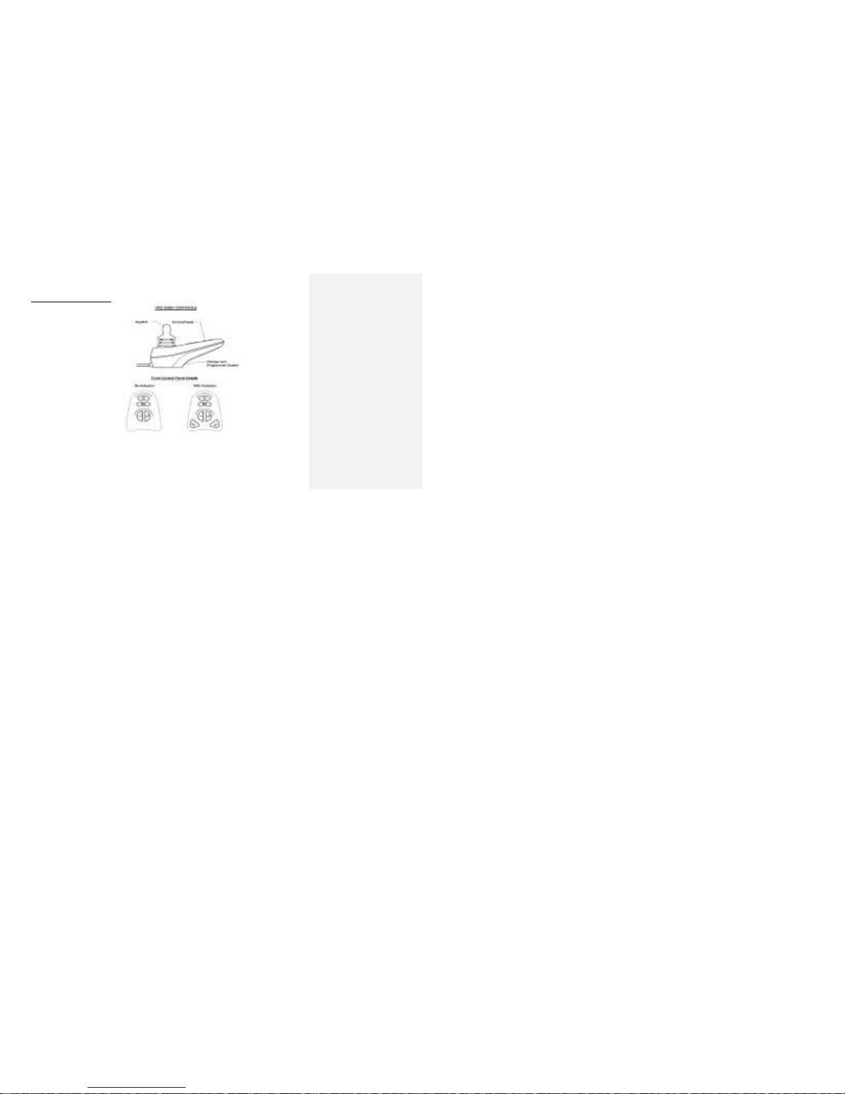
Magellan Explorer comes with the options of two available control system joysticks. See next page.
Page 25
3 MOVEMENT AND CONTROLS
730 REV 09 DATE REV: 09/02/14 25 POWER CHAIR: EXPLORER MAGELLAN
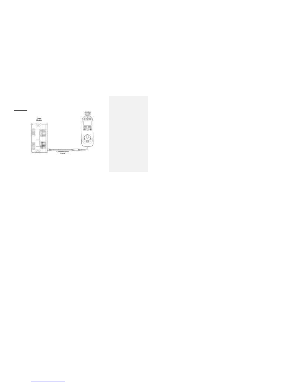
VR2 (standard joystick controller)
Figure 1
Visit http://www.futuremobility.ca/explorer-magellan-p-14.html to refer to VR2 operations manual for
more information.
Page 26
3 MOVEMENT AND CONTROLS
730 REV 09 DATE REV: 09/02/14 26 POWER CHAIR: EXPLORER MAGELLAN
R-NET (Optional - joystick controller with LCD screen)
Figure 2
Visit http://www.futuremobility.ca/explorer-magellan-p-14.html to refer to R-NET operations manual for
Page 27

4 HANDLING
730 REV 09 DATE REV: 09/02/14 27 POWER CHAIR: EXPLORER MAGELLAN
4 Handling
Explorer Magellan has been designed as a small and very stable power chair. If used improperly, however, there
is always the risk of accident or injury. FMH strongly recommends that you learn the characteristics of your
wheelchair and safe methods to perform the daily activities of your lifestyle in a controlled environment. Always
use common sense and good judgment when using Explorer Magellan.
Please consult healthcare professionals for advice and assistance to develop the skills and techniques you need
to safely use Explorer Magellan. Proper balance is the key to maintaining the stability of Explorer Magellan.
Reaching, bending, and transferring to or from the chair will change the weight distribution and center of gravity of
both yourself and Explorer Magellan.
Transfer activities.
Transferring into or out of a wheelchair is a very difficult maneuver and extreme care must be taken when
transferring without the aid of an attendant. Please make sure that the wheelchair is stabilized, and will not move
during your transfer. Take extra care to prevent tipping and use good body mechanics to avoid personal injury.
Seek help for transferring the wheel chair. The wheel chair has an option of transit hooks to prevent the chair from
moving during transit. Future Mobility recommends always using the transit hooks when in transit even when no
occupant is on board to prevent damage to the chair and the vehicle. Transferring while patient is seated on the
chair is difficult given the weight of the power chair alone is 208lbs with batteries. Ask for assistance to transfer
Page 28

4 HANDLING
730 REV 09 DATE REV: 09/02/14 28 POWER CHAIR: EXPLORER MAGELLAN
the chair. The batteries are heavy and to lift the chair would require more than 1 person to move it securely and
smoothly.
Reaching and Bending.
Position Explorer Magellan as close as possible to the object you wish to reach and reach only as far as your arm
will extend without changing your sitting position. If in doubt, reposition Explorer Magellan or ask for assistance.
Warning! Always ensure that the wheelchair is on a stable, level surface, is NOT in the
freewheeling mode, and that the wheelchair power is off before transfer. Remember,
the freewheeling mode disengages the motors and parking brakes, allowing the
wheelchair to roll. This is not a safe condition for transfers.
Warning! Do not step on the footboard or footrests when getting into or out of Explorer
Magellan; this could cause Explorer Magellan to tip forward. When transferring,
always fold the footboard up or swing the footrests away.
Warning! There is a critical moment during transfer when there is little or no seat support
beneath you. Please take every precaution to reduce this unsupported distance
before you attempt to transfer into or out of the wheelchair.
Page 29

4 HANDLING
730 REV 09 DATE REV: 09/02/14 29 POWER CHAIR: EXPLORER MAGELLAN
Ramps and Inclines.
Most people are capable of negotiating short inclines and declines using a power chair without assistance. Please
understand your own capabilities and practice with an attendant or healthcare professional before attempting to
negotiate an incline or decline independently. Always inspect the ramp for potential hazards such as holes,
Warning! Do not attempt to reach objects if you are required to move forward in the seat.
Do not attempt to retrieve objects from the floor if you must reach down between
your knees. Do not shift your weight in the direction that you are reaching and/or
bending as this could cause the wheelchair to tip.
Warning! Do not lean over the back of the seat back as this could cause Explorer Magellan to
tip.
Warning! NEVER reach or bend while driving your powered wheelchair. These actions
change the position of your center of gravity and can cause the wheelchair to
become unstable or difficult to steer.
Warning! NEVER allow your hands or feet near the wheels or other moving parts of the
wheelchair. Personal injury or damage to Explorer Magellan may result.
Page 30

4 HANDLING
730 REV 09 DATE REV: 09/02/14 30 POWER CHAIR: EXPLORER MAGELLAN
slippery or uneven surfaces, etcetera, before starting up or down. If you cannot see the entire ramp, please ask
someone to inspect it for you.
When ascending a ramp always face forward and lean the upper part of your body slightly forward, which will
increase stability. If you have to stop on the incline, please avoid any abrupt or sudden forward movement as you
resume climbing.
When descending a ramp always face forward and ensure that you are seated well towards the back of the seat.
Please descend slowly and steadily, allowing Explorer Magellan’s controller to maintain a slow safe speed
Curbs and Steps.
Curbs, steps and stairs are dangerous obstacles that confront wheelchair users. When you encounter curbs, find
a way around, or use the ramps now available in most locations. If you encounter steps and there is no ramp
Warning! Drive straight up inclines. Driving at an angle or trying to traverse a slope may result
in the wheelchair becoming unstable or difficult to steer.
Warning! NEVER place the wheelchair in freewheel mode while on an angled surface.
Freewheeling on a slope may allow the powered wheelchair to roll uncontrollably,
causing personal injury or damage.
Page 31

4 HANDLING
730 REV 09 DATE REV: 09/02/14 31 POWER CHAIR: EXPLORER MAGELLAN
available, do not drive up or down the steps. Avoid the steps by utilizing the designated elevators now required in
most locations.
Page 32

4 HANDLING
730 REV 09 DATE REV: 09/02/14 32 POWER CHAIR: EXPLORER MAGELLAN
Range
A significant increase in range can be achieved by smooth driving with Explorer Magellan. Any time rapid
acceleration or sharp, fast turns are used; a large amount of energy is consumed. If it is possible to accelerate
slowly and to drive at a steady speed with few sharp turns, the range you will achieve from each battery charge
will be greatly increased. This driving style will also increase the life of your batteries and the major drive
components of Explorer Magellan.
Warning! Explorer Magellan is not designed to negotiate steps. Personal injury and damage to
property will result.
Warning! Do not attempt to drive over curbs or obstacles. Doing so may cause your wheelchair
to tip or move in an unanticipated direction causing personal injury or damage to the
wheelchair. Explorer Magellan is not intended to climb or descend stairs or escalators.
Warning! It is extremely dangerous to move an occupied wheelchair up or down stairs by having
attendants lift the wheelchair. Do not do this. The probability of injury to the user’s and
attendant’s and property are very high. Use elevators provided at most locations.
Page 33

4 HANDLING
730 REV 09 DATE REV: 09/02/14 33 POWER CHAIR: EXPLORER MAGELLAN
Occupant’s weight.
The maximum allowable occupant weight for Explorer Magellan is 300 lbs (136 kg). Explorer Magellan has been
designed for stability and reliability with this maximum load. Safety and performance are compromised when this
value is exceeded. Additional passengers and heavy packages are not to be transported on Explorer Magellan.
General Operating Instructions.
1. Please charge the batteries fully before use. Nightly charging is encouraged.
2. Ensure that the drive wheels are ENGAGED by turning the free wheel levers so they point towards
DRIVE.
3. Adjust the speed control to low.
4. With the joystick in neutral, switch the wheelchair power ON
5. Move the joystick gently in the direction you wish to travel. If a higher speed is required adjust the speed
control knob.
6. To stop the wheelchair, release the joystick and allow it to return to the neutral position. The controller will
bring Explorer Magellan to a smooth stop. Almost immediately, a click will be heard, indicating the
automatic application of the electromechanical disc brakes.
Page 34
5 BATTERIES
730 REV 09 DATE REV: 09/02/14 34 POWER CHAIR: EXPLORER MAGELLAN
5 Batteries
Battery
Batteries are the single largest contributor to the safe and reliable performance of Explorer Magellan over its
lifetime. If you are able to properly service and maintain your batteries, many of the potential problems with any
power chair will be eliminated.
Even with proper maintenance, your batteries will need to be replaced periodically. As batteries age, their ability
to hold a charge decreases, making old batteries discharge much more quickly than new ones under the same
driving conditions. The result is a decrease in the distance the wheelchair can travel before batteries need to be
charged, which can often be misinterpreted as a problem with the wheelchair control/drive system. Properly
maintained batteries may be expected to last approximately 9 to 18 months, depending upon the level of use.
Explorer Magellan uses two Group 22NF batteries, which have an average capacity of approximately 55 amp
hours if discharged over a twenty-hour period. Only deep cycle gel cell or sealed lead-acid batteries should be
used with Explorer Magellan.
Warning! We know that you are excited to start using your Explorer Magellan, but in order to
have healthy batteries that have a long life, the batteries must be FULLY charged
before initial use.
Page 35

5 BATTERIES
730 REV 09 DATE REV: 09/02/14 35 POWER CHAIR: EXPLORER MAGELLAN
Guidelines to extend battery life.
1. Charge the batteries fully before using them for the first time.
2. Limit the use of new batteries for the first ten (10) discharge/charge cycles. Avoid discharging the
batteries deeply, i.e. no more than four LED should be unlit on the BDI.
3. Use the appropriate battery charger (supplied with Explorer Magellan). Using a charger provided with
other equipment, or a charger designed for unsealed batteries will damage the batteries and shorten their
life.
4. Recharge the batteries fully after every discharge. Leaving batteries partially discharged for several days
is not recommended as this could limit the amount of future charge they are capable of holding.
5. It is always best to allow the charger to finish its charge cycle once started. This will help prevent deeply
discharging the batteries. Batteries used on wheelchairs do not exhibit a significant “memory effect” and
will recharge to their full capacity even if only partially discharged before each charge.
Warning! The warranty and performance information in this manual are based on the use of
deep cycle gel cell or sealed lead-acid batteries.
Warning! Automotive batteries are not designed for the deep cycle energy draw that
wheelchair use requires. Do not use automotive-style batteries in your Explorer
Magellan.
Page 36

5 BATTERIES
730 REV 09 DATE REV: 09/02/14 36 POWER CHAIR: EXPLORER MAGELLAN
Battery Charging
Explorer Magellan is supplied with a 4-amp on-board switch-mode charger designed to charge sealed lead acid
batteries. This charger is permanently plugged into the control system at the connector underneath the front of the
seat. When charging is required, the 3-prong plug from the charger may be inserted into a 120V 50-60 Hz wall
outlet.
There is one light on the charger that will indicate the following charging conditions. A solid green light indicates
that charging is complete. A solid red/orange light indicates that charging is underway.
When the charge is complete, disconnect the charger from the wall outlet, and stow the cable. Explorer Magellan
is now ready for use.
The charger includes a fan for ventilation and cooling. As a result, it is common to notice an “electrical” smell
during charging. This is simply due to the air passed over the heated electrical components of the charger.
NOTE: Explorer Magellan’s controller includes and ‘inhibits’ line that prevents the wheelchair from driving when
the charger is plugged into the wall. It is possible that Explorer Magellan could move a few inches before the
inhibitor is fully activated. There is a delay of a few seconds between the removal of the charger from the wall
outlet and Explorer Magellan’s ability to turn on.
Page 37

5 BATTERIES
730 REV 09 DATE REV: 09/02/14 37 POWER CHAIR: EXPLORER MAGELLAN
Warning! NEVER attempt to charge the batteries by connecting the charger wires directly to the
battery terminals.
Warning! Some battery components (posts, terminals, etc.) contain lead compounds. Always
wash hands thoroughly after handling, or wear approved protective gloves. Eye
protection and a face shield are also recommended when working with batteries.
Warning! ALWAYS use the charger supplied with Explorer Magellan. Other types of chargers
may damage the batteries.
Warning! DO NOT remove the ground plug from the charger power cord. This will create
an electrical hazard. If necessary, use an approved 3-prong adapter for use with
a 2-prong outlet.
Warning! DO NOT attempt to recharge the batteries outside or when the wheelchair has
been exposed to any sort of moisture.
Warning! DO NOT plug in the on-board charger and an off-board charger at the same time.
Page 38

5 BATTERIES
730 REV 09 DATE REV: 09/02/14 38 POWER CHAIR: EXPLORER MAGELLAN
Battery Installation and Removal
The batteries on Explorer Magellan are individually packaged with a lid, connectors, and a strap. These battery
assemblies are NOT interchangeable. There is one battery assembly that must go at the front of the wheelchair,
and one battery assembly that must go at the rear of the wheelchair. The batteries on Explorer Magellan are
accessed from the rear of the chair.
Warning! It is important that you do not allow any tools or conductive material to directly
connect the two terminals of a battery. If you are not confident in your ability to attach
the lids to the batteries, ask your dealer for assistance.
Warning! Each battery weighs more than 14 kg. Be sure to use good body position and lifting
techniques when loading and unloading batteries.
Warning! Some battery components (posts, terminals, etc.) contain lead compounds. Always
wash hands thoroughly after handling, or wear approved protective gloves. Eye
protection and face shield are also recommended when working with batteries.
Warning! Connecting cables in a manner different than described may cause personal injury or
damage to the wheelchair.
Page 39
5 BATTERIES
730 REV 09 DATE REV: 09/02/14 39 POWER CHAIR: EXPLORER MAGELLAN
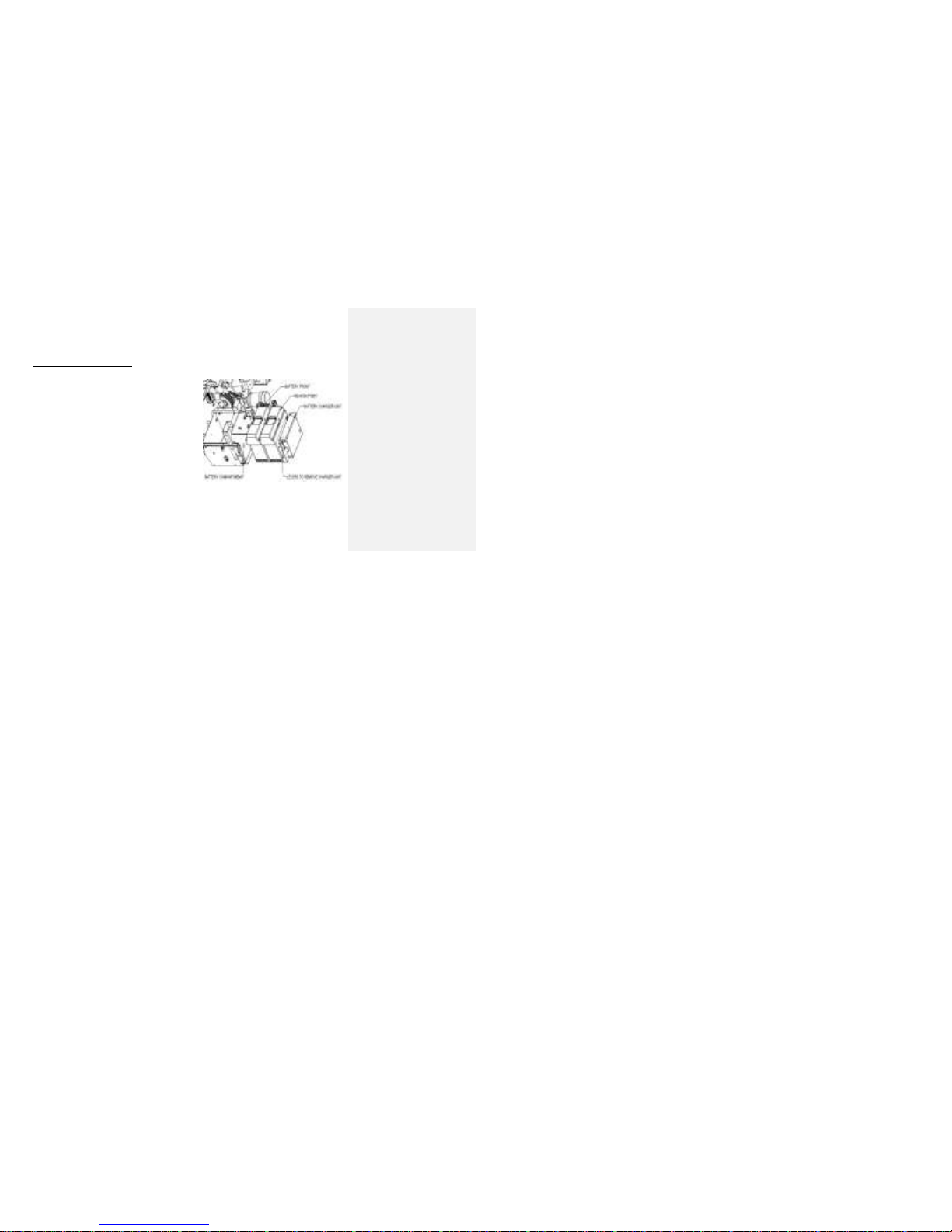
To install batteries in Explorer Magellan, follow these
steps.
Attaching battery lids to batteries.
a) Orient the battery lid as shown in Figure 3
b) Fasten the strap around the lid and battery until
they are securely held.
c) Carefully and securely, attach the terminal on
the red wire to the positive terminal of the
battery, and attach the terminal on the black
wire to the negative terminal of the battery. The
terminals should be pushed down as far as
possible on the posts.
d) Orient the battery lid as shown in Figure 3.
e) Fasten the strap around the lid and battery until
they are securely held.
f) Take the other battery and the lid with the
circuit breaker (white button) protruding from it.
This will be the Rear Battery Assembly.
g) Carefully and securely, attach the terminal on
the red wire to the positive terminal of the
Figure 3
Page 40
5 BATTERIES
730 REV 09 DATE REV: 09/02/14 40 POWER CHAIR: EXPLORER MAGELLAN
battery, and attach the terminal on the black
wire to the negative terminal of the battery.
Ensure that the terminals are pushed down as
far as possible on the posts and that they do
not interfere with the circuit breaker.
h) Take one battery and the lid with one red
connector and one black connector on it. This
will be the Front Battery Assembly.
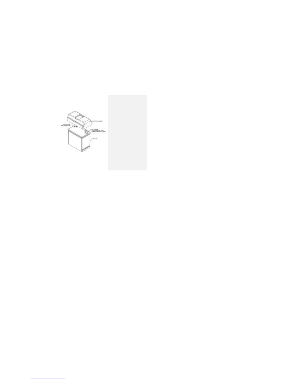
Installing the batteries in Explorer Magellan.
a) Using proper body positioning and lifting
techniques, place the Front Battery Assembly
on the battery tray so that the red connector is
on the right hand side of the wheelchair (when
sitting in Explorer Magellan) and the black
connector is towards the front of the
wheelchair.
b) Push the Front Battery Assembly halfway
towards the front of the wheelchair.
c) Move the Rear Battery Assembly, with the red
connector on the right and the circuit breaker
Figure 4
Page 41

5 BATTERIES
730 REV 09 DATE REV: 09/02/14 41 POWER CHAIR: EXPLORER MAGELLAN
facing the rear of the wheelchair, as close to
the battery tray as possible, but leave it on the
floor.
d) Attach the two red connectors together.
e) Move to the front of the wheelchair and route
the black connector from the Front Battery
Assembly so that it protrudes from the
wheelchair, between the front seat posts. It will
be inserted into the controller connector a little
later.
f) Returning to the rear of the wheelchair, use
good body position and lifting techniques to
place the Rear battery assembly on the battery
tray.
g) The cables and red connectors should be on
the right side of Explorer Magellan, and will fit
in between the battery and the chassis wall, in
the space created by the oversized battery lid.
h) Push both batteries towards the front of the
wheelchair as far as they will go. Be careful to
avoid snagging any cables on the nuts on the
Page 42
5 BATTERIES
730 REV 09 DATE REV: 09/02/14 42 POWER CHAIR: EXPLORER MAGELLAN
inside of the battery compartment.
i) Get the battery retention plate and orient it so
that the release levers are on the top and the
battery charger is showing at the rear of
Explorer Magellan.
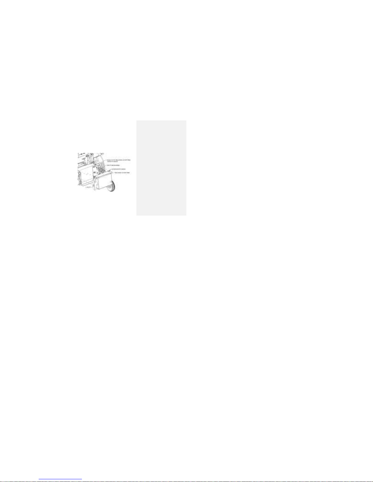
j) Slide the L-slot in the battery retention plate
over the bottom bushings in the battery tray
wall, and push it down to fully seat the bottom
bushings in their slots. The battery retention
plate is designed to be a very tight fit to reduce
rattling during Explorer Magellan use. Be firm
with the plate as you place it over the bushings.
k) Then, rotate the top of the plate forward, until it
is almost vertical as shown in Figure 5.
l) Push inward on the two release levers and
rotate the plate until it is vertical. Let go of the
release levers and ensure that the buttons
protrude through the chassis holes to lock the
battery retention plat in place.
m) Try to pull the battery retention plate towards
the rear of the wheelchair to ensure that it is
Figure 5
Page 43

5 BATTERIES
730 REV 09 DATE REV: 09/02/14 43 POWER CHAIR: EXPLORER MAGELLAN
properly secured. If the retention plate comes
off, return to step a), and repeat.
n) Ensure that the strap around the charger is
secure, and that the power cable is properly
stowed.
o) Move to the front of the wheelchair and firmly
insert the black connector into the socket
marked with a battery symbol on the controller
connector. This slot is the farthest one from the
cylindrical charger connector.
p) The batteries are now properly installed in
Explorer Magellan.
Removing the batteries from Explorer Magellan.
a) Follow the above process in reverse order.
Page 44

6 CHAIR ADJUSTMENTS
730 REV 09 DATE REV: 09/02/14 44 POWER CHAIR: EXPLORER MAGELLAN
6 Chair Adjustments
Concepts’ Arm Pad Position (Fore/Aft & Lateral)
The ‘Concepts’ arm pads (desk length and full length)
mount on the arm structure by inserting the flange nuts
provided into one of three slots in the bottom of the arm
pad. By choosing the appropriate slot, lateral adjustment
of the arm pad is achieved by placing it in narrow,
standard, or wide settings.
The ‘Concepts’ arm pads can also be adjusted in the fore
and aft direction. Before completely tightening the bolts in
the flange nuts, the arm pad may slide back and forth for
desired positioning.
NOTE: It is possible to set the fore and aft position of
the arm pad in such a way that flipping the arm
backwards interferes with the back cushion, or trying
to swing away the controller or access the
programmer port in the controller is made difficult.
Figure 6
Page 45
6 CHAIR ADJUSTMENTS
730 REV 09 DATE REV: 09/02/14 45 POWER CHAIR: EXPLORER MAGELLAN
When making adjustments, try all normal uses of
these components before tightening the settings
completely.
2 Point Traditional Arm Adjustments
A. Arm Height.
The arms may be adjusted in height through a range of
3 inches by pushing in the spring button at the front of
the arm and lifting the arm upwards until the desired
height setting is reached. The fabric side pouch has
been removed in the photo for clarity.
No tools are required for this adjustment.
B. Flip Back & Remove
The 2-point arms may be flipped back by pulling the tab
on the arm lock towards the user and rotating the arm
out of the way. Remove the arm by flipping it back,
pulling on the plunger knob, and sliding the arm
outward. To reinstall the arm, hold it in the rotated
Figure 7
Page 46
6 CHAIR ADJUSTMENTS
730 REV 09 DATE REV: 09/02/14 46 POWER CHAIR: EXPLORER MAGELLAN
position, pull on the plunger knob and slide the rear
cylinder over the arm pivot.
C. Arm Position (Fore/Aft & Lateral)
The arm may be positioned over a wide fore-aft range.
Use a ¼” Allen hex key or bit to adjust the locking bolt
under the arm rail. Slide the arm to the desired position
and tighten the locking bolt. If a greater adjustment
range is required, remove the locking bolt, reposition it
in a different hole under the arm rail, and tighten the
bolt when the desired position is achieved.
Back Adjustments
A. Back Position
The back may be moved relative to the base over a
four-inch range. To move the back, loosen the four hex
head bolts under the seat frame with a 1/2" wrench.
The back support bracket can then be repositioned on
the seat support frame by sliding the bracket along its
Figure 8
Page 47
6 CHAIR ADJUSTMENTS
730 REV 09 DATE REV: 09/02/14 47 POWER CHAIR: EXPLORER MAGELLAN
slots. All four bolts must then be securely refastened to
150 in lbs of torque. Adjusting the location of the back
changes the effective seat depth. Seat depth is
measured from the front of the seat pan to the point
where back pivot bracket protrudes from the seat pan.
B. Back Angle Adjustment Style
i. Manual Recline Angle (all backs) The angle of
the back may be adjusted through a range of 5
forward to 40 back with a gas spring assist. To
adjust the angle move the release lever “A”, in
Figure 9, forward, move the back to the new
position and then release the lever. The back has
a level of pre-tension and will wish to return to the
most forward position when the release lever is
moved forward. The release lever is always
activated by pushing forward, whether recline
angles are being increased or decreased.
Figure 9
Page 48
6 CHAIR ADJUSTMENTS
730 REV 09 DATE REV: 09/02/14 48 POWER CHAIR: EXPLORER MAGELLAN
Tools required: None. This adjustment is best
made when sitting in the chair.
ii. Fixed Angle (all backs) The Fixed Angle
adjustment style allows a back angle range of 5
forward to 15 back. This back angle setting is
adjusted using the handle installed. Loosen the
handle on the side of Explorer Magellan, move
the back to the desired angle, and securely
tighten the handle. (NOTE: In order to operate in
the limited space at the rear of Explorer
Magellan, the handle can be used somewhat like
a ratchet. Pull the handles outwards, rotate it to a
new position, and then use the new position of
the handle on the bolt to tighten the connection
further.) It is important to NEVER loosen the bolt
on the other side of Explorer Magellan (cylindrical
head with hex socket in it). This second bolt must
remain secure at all times and is not part of the
adjustment process.
Figure 10
Page 49

6 CHAIR ADJUSTMENTS
730 REV 09 DATE REV: 09/02/14 49 POWER CHAIR: EXPLORER MAGELLAN
Tools Required: 3/16” Allen hex key
C. Back Adjustments
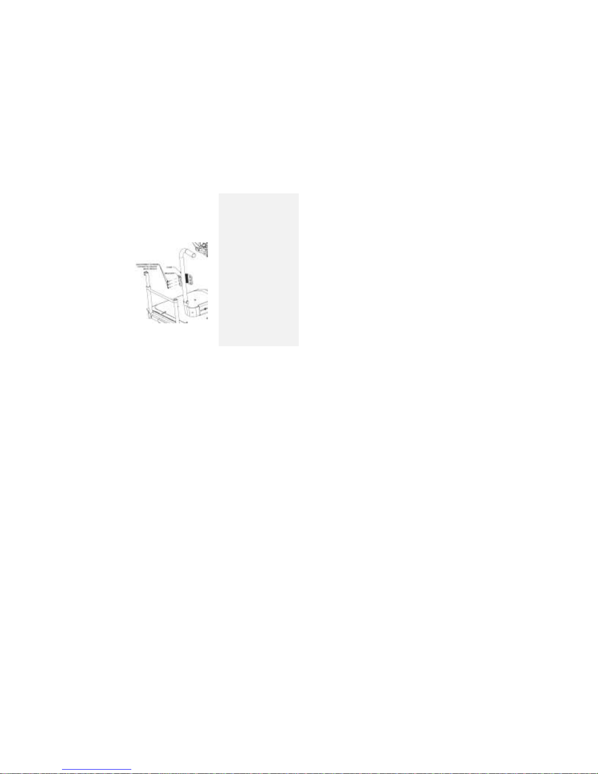
i. Back Width – The PRISM backs are provided in
standard widths and are not adjustable.
ii. Back Height Location The location of the PRISM
back can be changed by using a 3/16” Allen key.
Figure 10 shows Three Adjustment Cap Screws
which can be loosened and then adjusted to suit
the back height that the end user requires. The
Back Hardware on the other side of the chair has to
adjust to the same height to ensure the back fits in
place and is not loose. Once the back hardware is
secured in place, the PRISM back can be placed
back onto the chair.
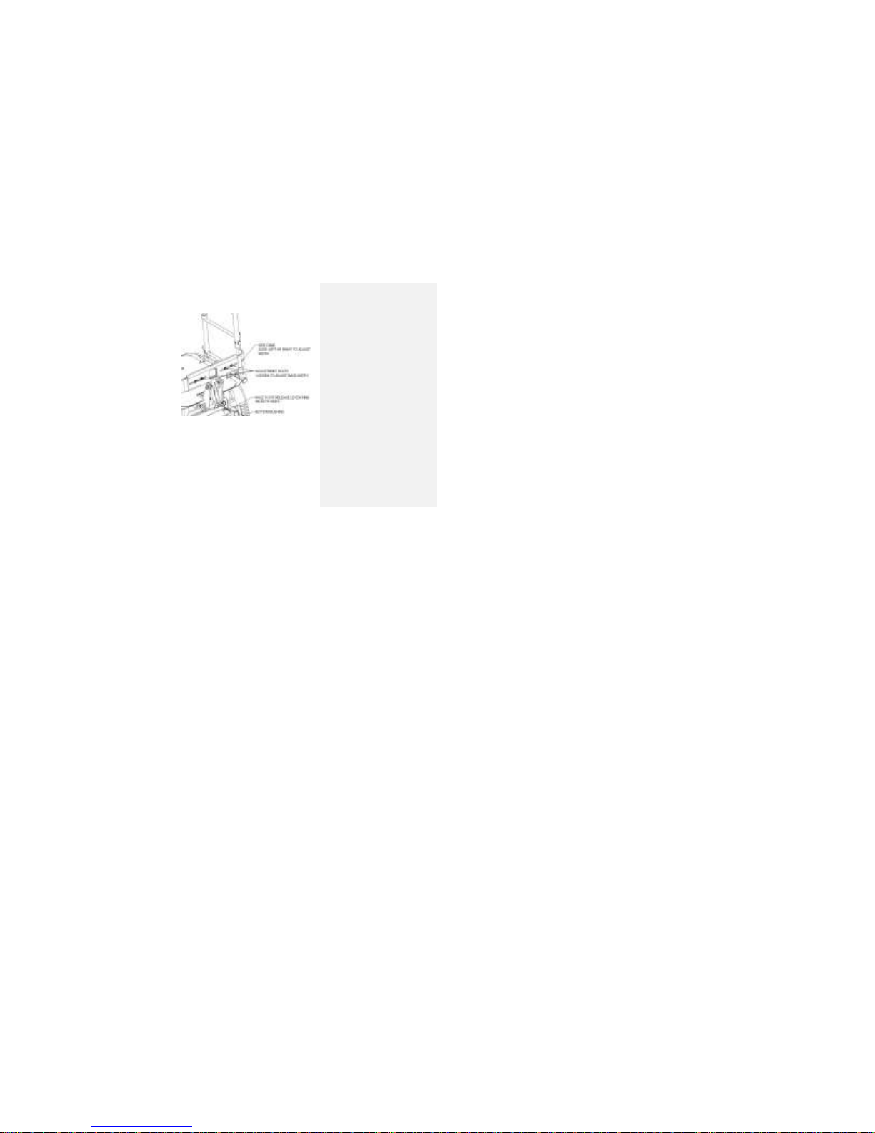
D. Cane Back Adjustments
i. Width
Page 50
6 CHAIR ADJUSTMENTS
730 REV 09 DATE REV: 09/02/14 50 POWER CHAIR: EXPLORER MAGELLAN
The vertical side canes can be set to widths of 16 to 24
inches in one-inch increments. This width
measurement is made between the outside surfaces of
the vertical tubes.
a. To adjust the cane back width use a 7/16”
wrench to loosen the four nuts at the back of the
assembly.
b. Slide the side canes to the appropriate width
positions. Be sure to set the width symmetrically
about the center of the wheelchair.
c. When the overall width, measured from the
OUTSIDE of the vertical tubes, is at the desired
value, retighten the nuts.
Tools required: 7/16” wrench or socket
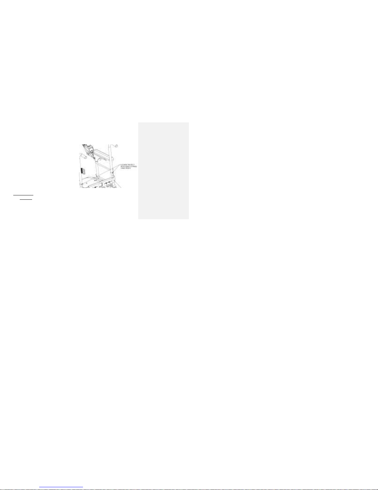
ii. Height
The push handles on the cane back are adjustable over
a 4” range. Measured from the top of the seat pan to
the top of the push handles, they may be set at 22”,
23”, 24” or 25”.
Figure 11
Page 51
6 CHAIR ADJUSTMENTS
730 REV 09 DATE REV: 09/02/14 51 POWER CHAIR: EXPLORER MAGELLAN
a. To modify the height of the push handles, remove
the bolts, nuts, and washers on the bottom of the
push handle, using the Phillips screwdriver and
7/16” socket or wrench.
b. Move the push handles vertically until the
appropriate hole is aligned.
c. Reinstall the bolts, washers, and nuts and
secure.
NOTE: It is also possible to install the push handles so
they point inward towards each other. Be sure that this
will not interfere with the back cushion installation
before attempting.
Tools required: Phillips screwdriver, 7/16”
wrench or socket
Seat Adjustments
A. Seat Depth
In conjunction with the back position, seat position
Figure 12
Page 52
6 CHAIR ADJUSTMENTS
730 REV 09 DATE REV: 09/02/14 52 POWER CHAIR: EXPLORER MAGELLAN
results in seat depths of 17, 18, 19 and 20 inches on
Explorer Magellan. The seat pan remains in place and
the back location is adjusted fore and aft to achieve the
desired seat depth. It is customary to set seat depths to
the nearest inch, but the range is continuously
adjustable so other depths may be set as required.
Four bolts under the seat frame must be loosened with
a 1/2" wrench or socket to allow repositioning. Tighten
the bolts to 150 in lbs of torque when proper location is
determined. For 17” seat depth, the back must be at
the front of the slots while for 20” seat depth, the back
must be at the rear. Seat depth is measured from the
front of the waterfall curve of the seat pan to the point
at the rear bracket emerges from the seat pan.
Tools required: 1/2" wrench or socket
B. Seat Height/Angle
The seat height may be set 17, 18 or 19 inches for the
solid seat pan (measured to the top surface at the front
Figure 13
Page 53
6 CHAIR ADJUSTMENTS
730 REV 09 DATE REV: 09/02/14 53 POWER CHAIR: EXPLORER MAGELLAN
of the seat pan with a 4 angle). The front seat height
and rear seat height are adjusted independently as
described below.
The following method will allow seat height changes to be
performed with the least difficulty.
i. Preparation
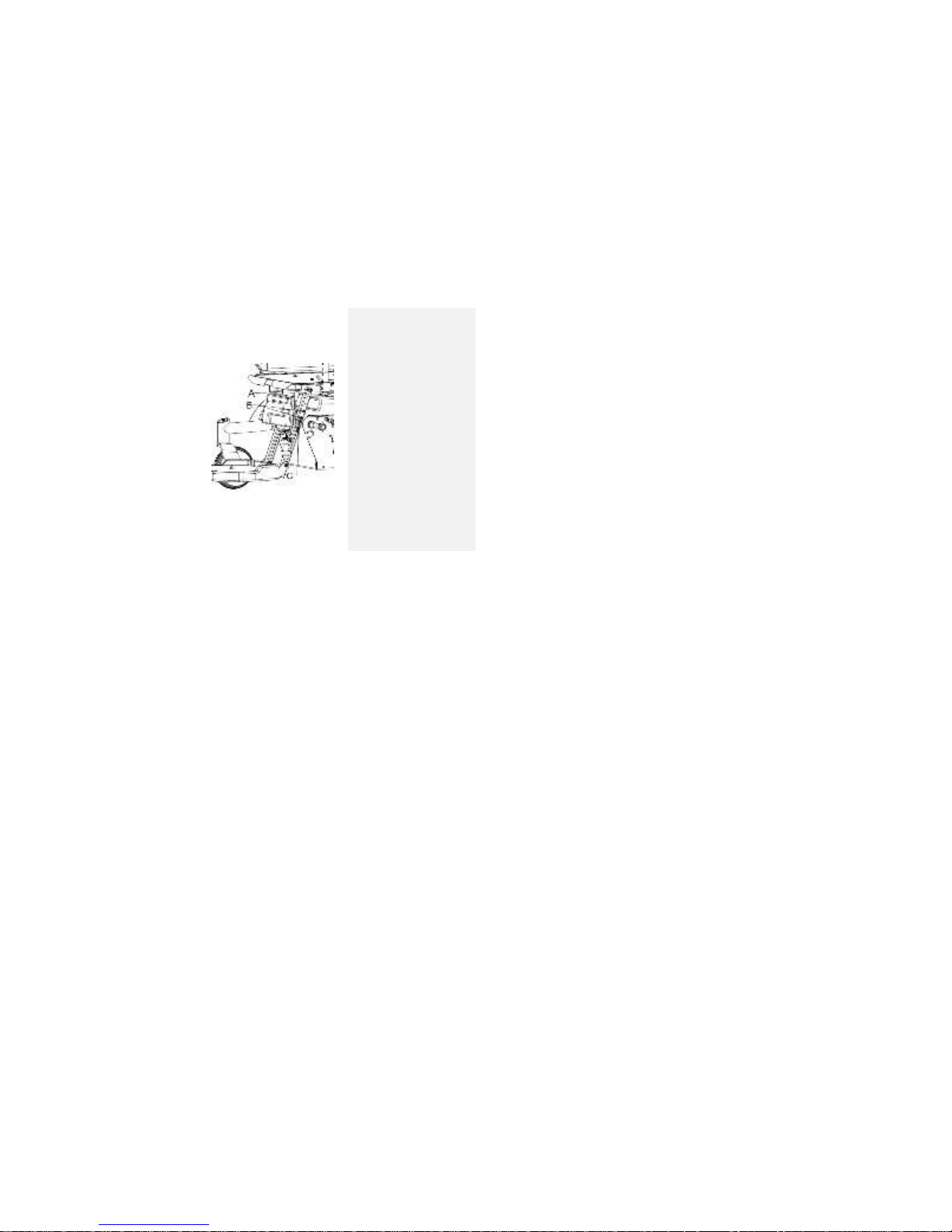
Loosen, but do not remove, the bolts labeled as
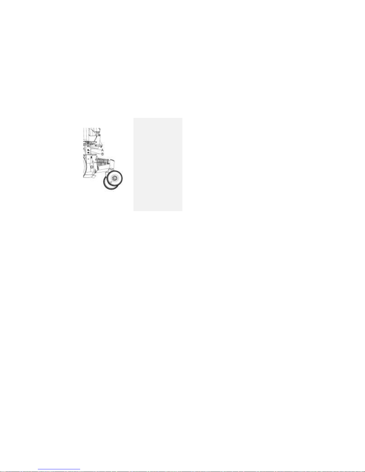
“A” in Figure 13 and A in Figure 14 (obscured in
picture, but access hole is shown). A 1/4" Allen
key or bit, ratchet and ratchet extension is
required. This will allow the various parts to rotate
and automatically adjust to the configuration
change. If you choose to omit this step, the
adjustments may still be made, but they will be
stiff and may need significant persuasion.
ii. Rear Seat Support
Remove the 1/4-20 bolts and split washers from
the upper portion of the Rear Seat Support
Figure 14
Page 54

6 CHAIR ADJUSTMENTS
730 REV 09 DATE REV: 09/02/14 54 POWER CHAIR: EXPLORER MAGELLAN
(labeled A in Figure 14) using a 3/16” Allen key or
bit. Once these four bolts are removed, the rear
support and seat are no longer anchored and will
tend to fall downwards. It can be useful to place
a piece of wood under the rear seat support arch
to it in place. Move the rear seat support until the
holes line up with the desired setting and reinstall
the 1/4-20 bolts and split washers, tightening to
150 in lbs of torque.
iii. Front seat support
To keep the same angle and just raise or lower
the seat height the same amount as the back,
loosen and remove the four bolts and split
washers near the top of the seat posts, labeled B
in Figure 13. Lift or lower the seat frame to the
desired height. Align the holes and reinsert the
bolts and split washers. This connection needs to
be tight. To change the seat angle, adjust the
location of the four bolts, flat washers and nuts at
the midway point of the front seat post. Each hole
Page 55
6 CHAIR ADJUSTMENTS
730 REV 09 DATE REV: 09/02/14 55 POWER CHAIR: EXPLORER MAGELLAN
increment changes the angle around
approximately 3 degrees. Use a wooden block or
a have a helper hold the seat steady and lift and
lower it to the desired angle setting. Reinstall the
bolts, flat washers and nuts and tighten. This
connection needs to be firm, but not crazy-tight
(crazy-tight can collapse the square tube!)
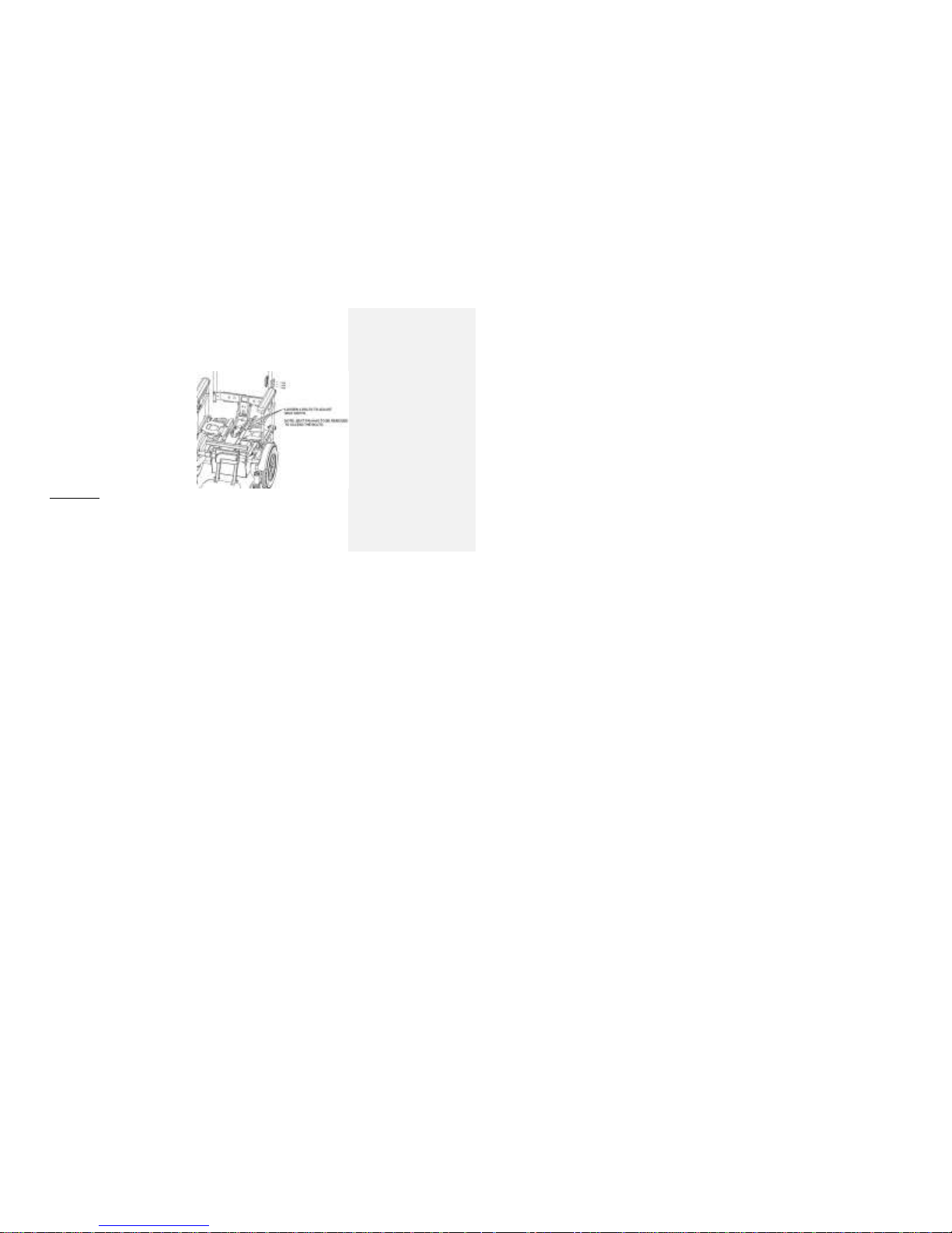
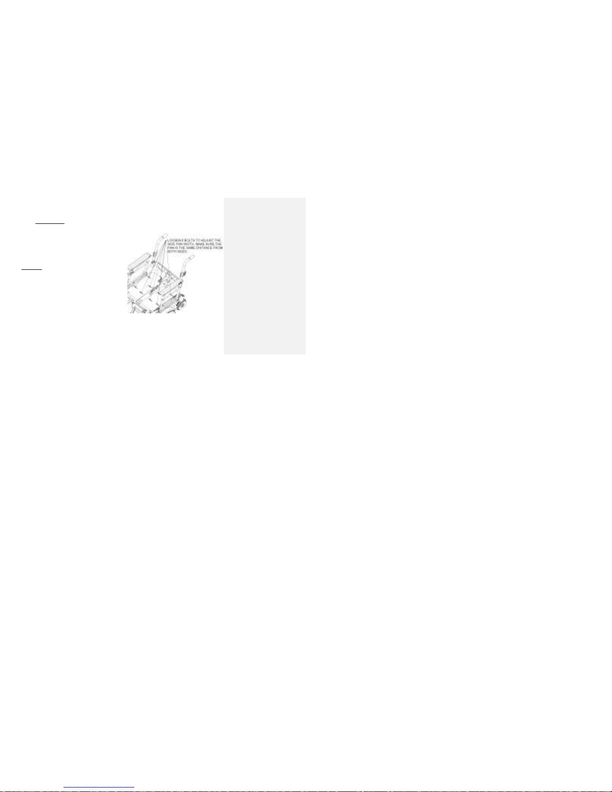
iv. Seat width adjustment
Remove the seat pan cover and loose the nuts
shown in the picture. The slots will allow for wider
range of seat adjustments. Set to desired width
and retighten the bolts to 150ft.lb torque to make
sure that the adjustment is fixed and will not
move upon sitting.
Figure 15
Page 56
6 CHAIR ADJUSTMENTS
730 REV 09 DATE REV: 09/02/14 56 POWER CHAIR: EXPLORER MAGELLAN
Tools required:
1/4" Allen hex key or bit
3/16” Allen hex key or bit
3/16” Allen hex key or bit,
7/16” wrench or socket
1 - 1/4" Allen hex key or bit
2 - 1/4" Allen hex key or bit
Free Wheel
When storing an unoccupied powered wheelchair, or
moving it into a vehicle for transport, it is sometimes
useful to be able to roll the wheelchair without the use of
the motors. Disengaging the motors is known as a
‘freewheel’ condition.
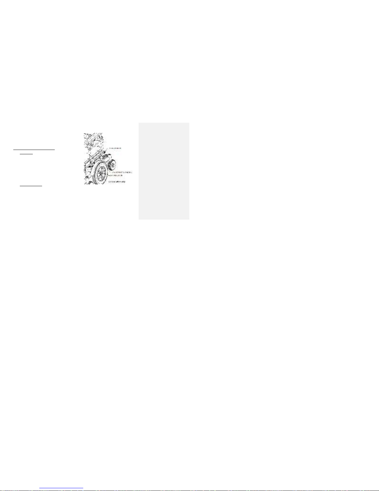
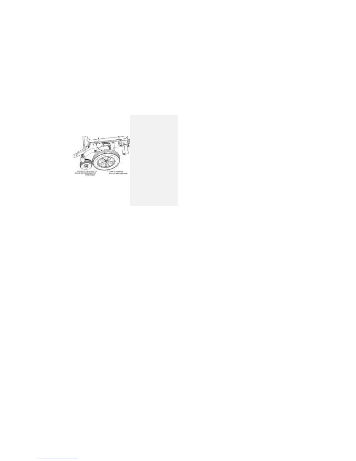
Each motor is equipped with a freewheel lever, located
on the top surface of the fender, above each gearbox. To
engage the motors so they may be controlled with the
joystick, turn the free-wheel lever so it points to the rear
of the wheelchair. To disengage the motors, turn the free-
Figure 16
Page 57
6 CHAIR ADJUSTMENTS
730 REV 09 DATE REV: 09/02/14 57 POWER CHAIR: EXPLORER MAGELLAN
wheel lever so it points outward towards the wheel as
shown in Fig 16.
Tools required: None. The free wheel levers
are turned by hand.
Figure 17
Page 58

6 CHAIR ADJUSTMENTS
730 REV 09 DATE REV: 09/02/14 58 POWER CHAIR: EXPLORER MAGELLAN
Warning! Once the motors have been placed into freewheel mode (motors disengaged), the
parking brakes DO NOT operate and the controller CANNOT steer the wheelchair.
Freewheeling must NOT be used with an occupied wheelchair, or on a slope.
Warning! Always turn the wheelchair controller power off before engaging or disengaging
the motors with the freewheel levers.
Warning! NEVER place the wheelchair in freewheel mode while on an angled surface.
Freewheeling on a slope may allow the powered wheelchair to roll uncontrollably,
causing personal Injury to a user or attendant, or damage to the wheelchair or
property.
Page 59
6 CHAIR ADJUSTMENTS
730 REV 09 DATE REV: 09/02/14 59 POWER CHAIR: EXPLORER MAGELLAN
Front Riggings
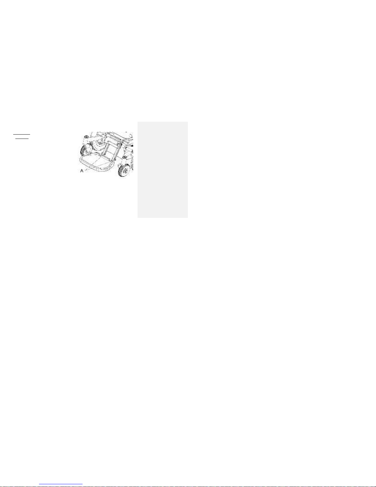
A Footboard
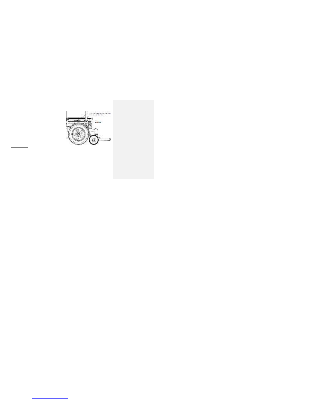
The distance from the top of the footboard to the top
of the seat pan may be adjusted through a range
between 12 and 15 inches. Do this by removing the
bolts shown as “A” in Figure 17, repositioning the
footboard to the height required, and re-installing the
bolts. The distance between each hole on the vertical
footboard support tubes is 1/2". Tighten the bolts
sufficiently to provide the footboard with enough
friction for it to remain upright when flipped back for
transfers. To adjust the angle of the footboard, flip the
footboard up, and loosen the bolts on the bottom of
the footboard at each side. Slide the angle stops to
the desired position, and tighten the screws. Ensure
that both stop are adjusted equally, so each side
supports half the load.
Tools required: 3/16” Allen hex key, 7/16”
wrench or socket, 5/32” Allen hex key
Figure 18
Page 60

6 CHAIR ADJUSTMENTS
730 REV 09 DATE REV: 09/02/14 60 POWER CHAIR: EXPLORER MAGELLAN
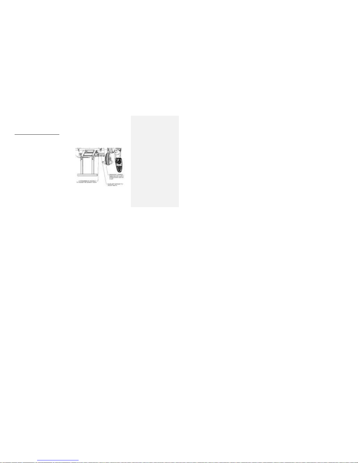
B. Swingaway Footrests
To change the length of the swingaway footrest
assembly, remove the hex head bolt and nut on the
footrest tube and adjust the length, and reinstall the
bolt in the desired hole location. Tighten the bolt
completely before installing the nut. Tighten the nut to
lock the adjustment in place. The angle of the
footrests is not adjustable.
To ‘swingaway’ the footrest assembly, push the
release lever, B, in Figure towards the middle of
Explorer Magellan. This disengages the locking
mechanism, and allows the footrest to rotate outward.
To completely remove the footrest from Explorer
Magellan, rotate it outward, and lift it up. To reinstall
the footrests, orient the footrest so the footplate is
pointing out from the side of Explorer Magellan. Insert
the front rigging plug into the bracket, and rotate
towards the front of Explorer Magellan to lock the
release lever in place.
Page 61
6 CHAIR ADJUSTMENTS
730 REV 09 DATE REV: 09/02/14 61 POWER CHAIR: EXPLORER MAGELLAN
Tools required: 7/16” wrench or socket
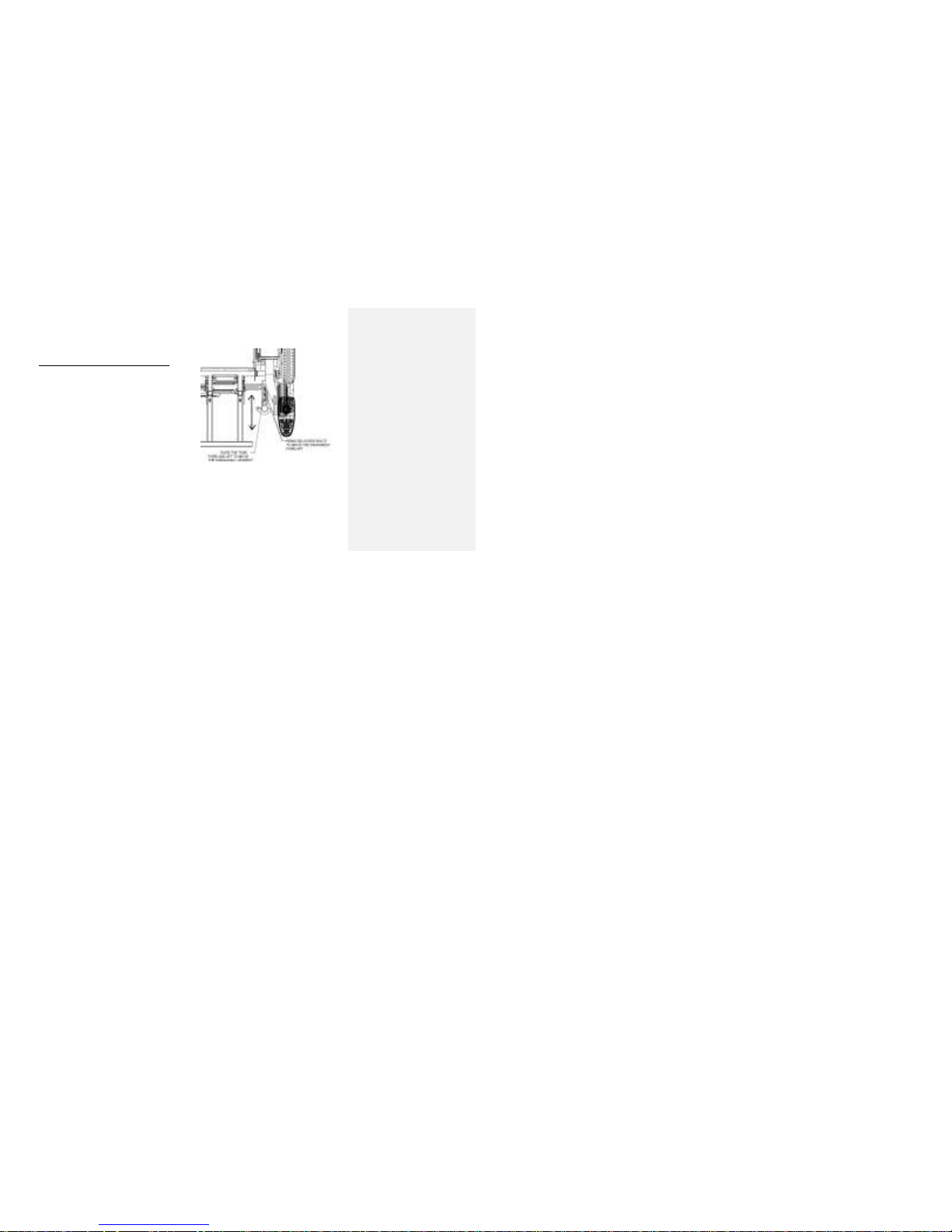
C. Swing away Footrests width adjustments
The footrest brackets can be set to widths of 16 to 20
inches in one-inch increments for the small seat
frame and 20 to 24 inches for the large seat frame.
To adjust the bracket width, follow this procedure:
1. Use the 1/2” wrench to remove the four 5/16”-18
bolts and split lock washers underneath the
legrest adapters at the front of the seat frame.
2. Slide the legrest adapters to the appropriate
width positions. The legrest adapters may be
moved in 1/2” increments, affecting the overall
width by 1”. Be sure to set the width
symmetrically about the center of the wheelchair.
3. When the overall width, measured from the
OUTSIDE of the vertical tubes, is at the desired
value, reinstall the four bolts and lock washers in
the appropriate holes under the back post
Figure 19 Upside Down View of Chair (front edge)
Page 62
6 CHAIR ADJUSTMENTS
730 REV 09 DATE REV: 09/02/14 62 POWER CHAIR: EXPLORER MAGELLAN
assembly, and tighten to 205 in lbs.
Tools required: 1/2" wrench, torque wrench
D. Swing away Footrests - Fore/Aft adjustments
The footrest brackets may also be adjusted front to
back over a 3-inch range in 1/2" increments. To
modify the setting of the footrest brackets perform the
following steps:
1. Use the 1/2" wrench to remove the four 5/16-18
bolts and split lock washers underneath the
footrest brackets at side of Explorer Magellan.
2. Slide the footrest brackets to the appropriate
fore/aft position. The footrest brackets may be
moved in 1/2" increments. Unless asymmetry is
required, be sure to set the brackets to the same
setting on each side of Explorer Magellan.
3. Reinstall the four bolts and lock washers in the
appropriate holes and tighten to 205 in lbs.
Tools required: 1/2" wrench, torque wrench
Figure 20 Upside down view of the front of the chair (front edge)
Page 63
6 CHAIR ADJUSTMENTS
730 REV 09 DATE REV: 09/02/14 63 POWER CHAIR: EXPLORER MAGELLAN
Anchor Brackets
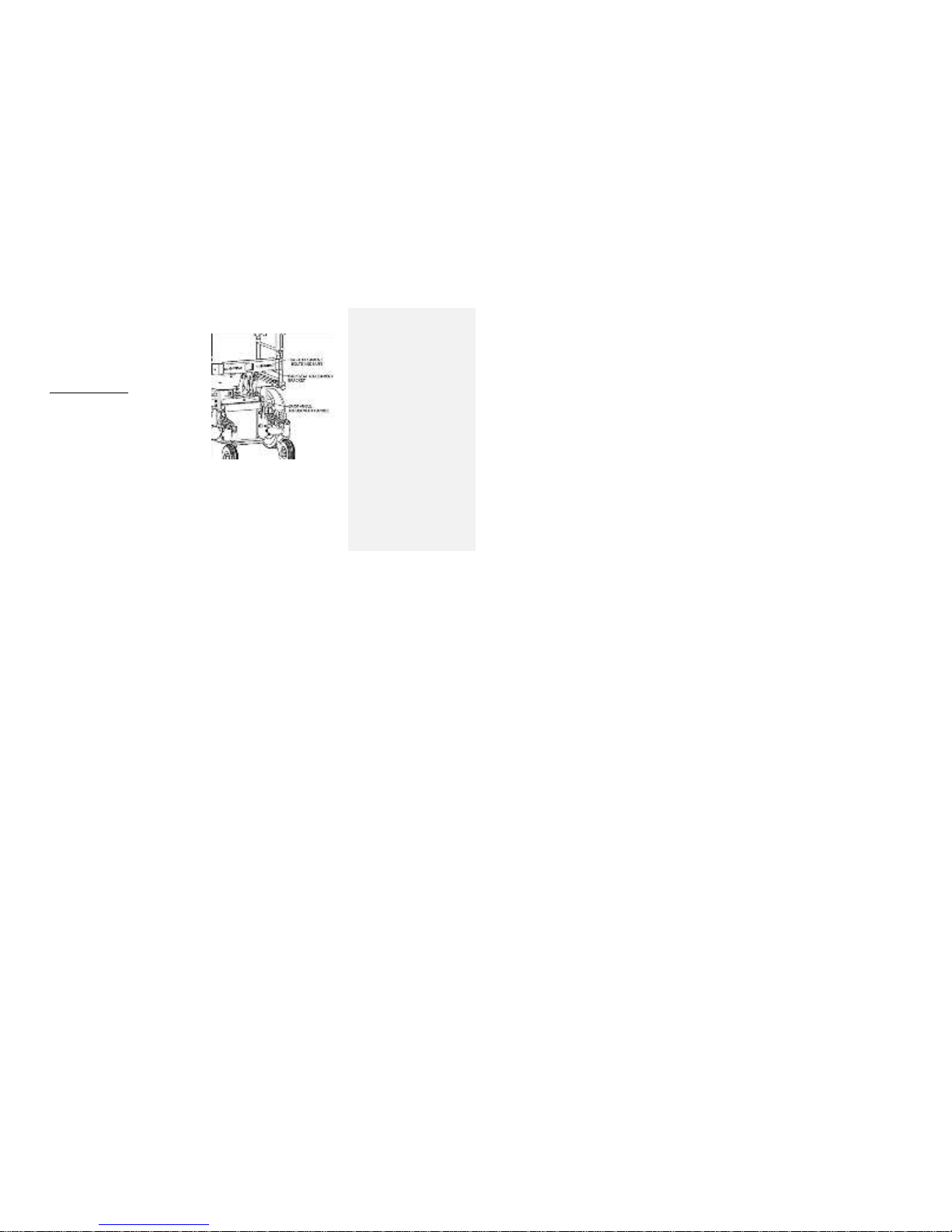
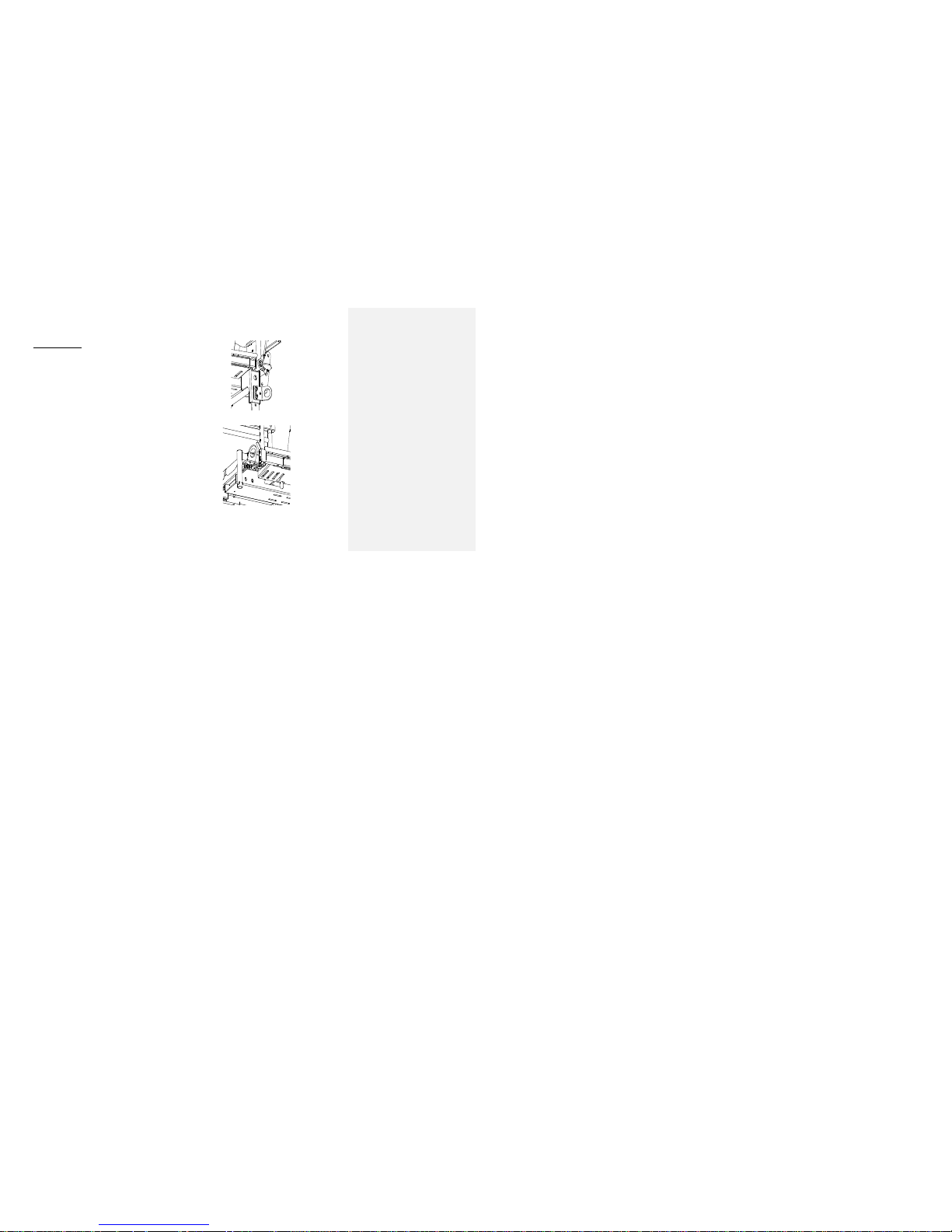
Anchor brackets are installed in the front and rear of
the Explorer Magellan chair as shown below.
Note: There should be a total of 4 (four) anchor
brackets. 2 brackets in the front and 2 brackets in the
back of the chair.
Figure 21
Figure 22
2 -1/4”-20 x 7/8” Socket
Head Capscrew and
2-1/4” Lock washers
Rear Support
Bracket
2 – 5/16”-18 x 1 Hex Head
Capscrew, 2-5/16” Flat Washers
Legrest
Adapter
Page 64

7 CLEANING INSTRUCTIONS
730 REV 09 DATE REV: 09/02/14 64 POWER CHAIR: EXPLORER MAGELLAN
7 Cleaning Instructions
Seat and Back
Remove the outer and inner cover if required and hand wash with a small amount of detergent
o Hang to dry, do not machine dry or wring out
Use multipurpose disinfectant to spray seat, scrub with soft brush.
o Test an inconspicuous area first for colour-fastness
DO NOT USE HOT AIR FOR DRYING.
DO NOT IMMERSE the cushion or back foam in water or cleaning solution.
Some color leeching from the cover and dying the foam is normal and cannot be washed out
Frame, Armrest, Footrests And Other Components
Spray the frame and components with multi-purpose disinfecting detergent, scrub with soft brush.
Rinse well and dry with a soft cloth.
DO NOT USE HOT AIR FOR DRYING.
By wiping down with a soft cloth after rinsing mildew buildup will be minimized.
IMPORTANT:
DO NOT USE ABRASIVE POWDERS OR SCOURING PADS ON PAINTED SURFACES
DO NOT SUBMERGE CHAIR IN WATER
RINSE WITH A DAMP RAG AFTER CLEANING TO ENSURE THAT ANY SOAP RESIDUE IS REMOVED
DO NOT USE CLEANING PRODUCTS WITHOUT CONSULTING THE PRODUCTS’ INSTRUCTIONS AND
TAKING APPROPRIATE PRECAUTIONS FOR HUMAN EXPOSURE TO CHEMICALS
Page 65
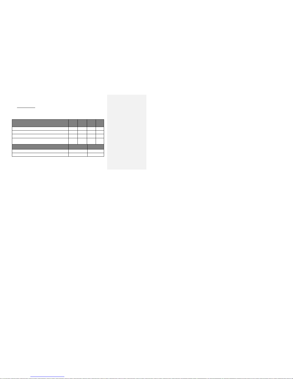
8 LIMITED WARRANTY
QSF: 390 –UM 1024409 REV02 09/19/13 65 POWER CHAIR: EXPLORER MAGELLAN
8 Limited warranty
The warranty on Orion Explorer Magellan applies only to the original purchaser or owner of the product.
Future Mobility Healthcare Inc. (FMHI) warrants Orion Explorer Magellan against defects in material and
manufacturing as listed below.
Warranty Period
Orion Explorer Magellan Power Wheelchair
6
months
18
months.
2 years
5
years
a. Base, seat frame and drive and caster wheel hubs (not tires)
*
b. Controller, charger and cables.
*
c. Motors and gearboxes.
*
d. Upholstery, plastic and rubber components, bearings, front
rigging, forks and all other parts not specifically identified above.
*
Replacement parts. **
3 months 6 months
a. New motors, controllers and chargers.
*
b. Remanufactured motors, controllers and chargers.
*
Page 66
8 LIMITED WARRANTY
QSF: 390 –UM 1024409 REV02 09/19/13 66 POWER CHAIR: EXPLORER MAGELLAN
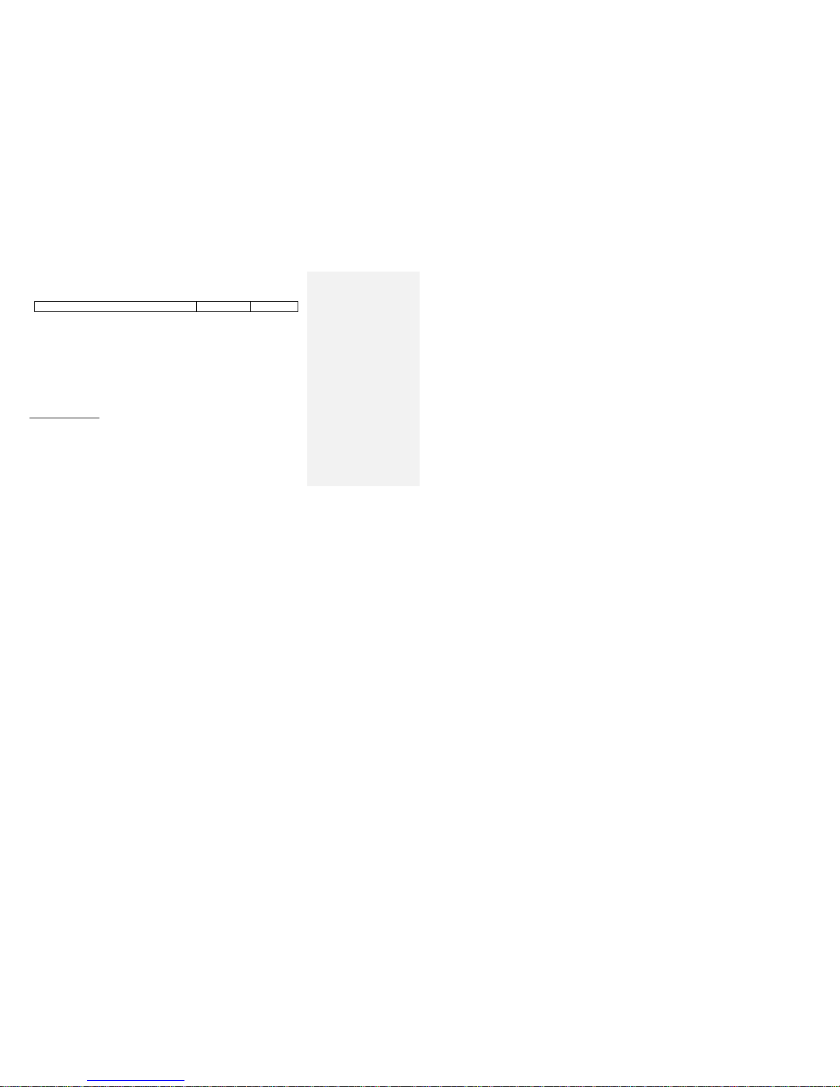
c. All other components
*
* The average life expectancy of a wheelchair under normal everyday use is approximately five years.
** If a part is replaced under warranty, the original warranty period will not be affected.
The warranty period for the consumer commences on the first date a product is delivered to the consumer from
the seller/dealer. If the product is rented or leased, the warranty period commences on the invoice date from
FMHI or its authorized distributor.
If within the warranty period, the product or component is proven to FMHI’ satisfaction to be defective, such
product or component shall be repaired or replaced at FMHI’ option.
FMHI’ sole obligation and your exclusive remedy under this warranty shall be limited to such repair and/or
replacement. This warranty does not include any labor charges incurred in the installation of the replacement
part(s). Also freight charges to the manufacturer are at the expense of the consumer or purchaser.
Limitations and Exclusions.
The above warranty shall not apply to serial numbered products if the serial number has been removed or
defaced. Products subjected to neglect, abuse, improper use, maintenance or storage, or damages beyond
Page 67

8 LIMITED WARRANTY
QSF: 390 –UM 1024409 REV02 09/19/13 67 POWER CHAIR: EXPLORER MAGELLAN
FMHI’ controls are not covered by this warranty, and solely FMHI shall determine that evaluation. Also the
warranty shall not apply to products modified without FMHI’ written consent; nor shall it apply if components not
supplied by FMHI are added to the product, or if someone not authorized by FMHI services the product.
Page 68

8 LIMITED WARRANTY
QSF: 390 –UM 1024409 REV02 09/19/13 68 POWER CHAIR: EXPLORER MAGELLAN
For warranty service, please contact the authorized dealer from whom you acquired your Orion Explorer
Magellan. In the event you do not receive satisfactory service, please communicate directly with FMHI. The
contact information for FMHI is given at the end of this document. Please do not return products to FMHI without
prior authorization. Products returned to FMHI without prior authorization will not be accepted.
Page 69

8 LIMITED WARRANTY
QSF: 390 –UM 1024409 REV02 09/19/13 69 POWER CHAIR: EXPLORER MAGELLAN
Please fill in the information for your dealer for future reference:
Dealer Information
Name of Dealership:
Address:
Contact Name:
Phone:
Fax:
Email: Product:
Orion Explorer Magellan By Future Mobility Healthcare Inc.
Serial Number:
Page 70

Page 71

Page 72

 Loading...