

FuturaSun FU P Series, FU M Series Safety And Installation Manual

SAFETY AND
INSTALLATION
MANUAL
Photovoltaic Module FU XXX P / M
Author: FuturaSun
Document name: Installation_manual_FuturaSun_2017
Revision date: 07.08.2017

CONTENTS
1. General Information ..................................................................................................................... 3
2. Disclaimer of Liability ................................................................................................................... 4
3. IEC 61215 & 61730 certifications ................................................................................................. 4
4. Limited Warranty .......................................................................................................................... 4
5. Module Specification .................................................................................................................... 4
6. Safety Precautions ....................................................................................................................... 4
7. Installation .................................................................................................................................... 5
8. Use and Maintenance .................................................................................................................. 8
9. Packaging, Handling and Storage of Modules ............................................................................. 9
10.Temperature coefficients………………..………………………………….………………………….11
FuturaSun srl – The specifications in this manual are subject to revisions without further notice
2
1. General Information
East
b
South
Fig.2
The photovoltaic (PV) modules, FU XXX P, FU
XXX M, (hereafter “FU XXX”) are devices that
produce electrical energy by converting the
sunlight’s radiation reaching their surface, when
appropriately exposed, into continuous/direct
current (DC).
The FU modules are intended to be used in
photovoltaic module systems connected to the
electrical grid. It is also possible to use them in
battery powered photovoltaic module systems
(stand alone).
The rated currents at Standard Test Conditions
(STC) of the FU modules are variable depending
on the model and the relative power rating, as
indicated in the respective technical data sheets.
Most of the electrical parameters of the modules,
specified in the datasheets, are determinable only
by using special instrumentation in the laboratory;
therefore, only some of them are measurable
outside of a lab, using common instrumentation
(voltmeter, AM meter, solarimeter/pyranometer).
It is possible, following very precise procedures, to
carry out electrical measurements of voltage and
current as snapshots, which enable you to monitor
the operation of the modules and determine
possible, although rare, anomalies.
The electrical output parameters for FU modules,
of technical importance during the operation,
installation and maintenance, are the following:
• Voltage at open circuit (Voc) with tolerance
of ± 4%
• Current at short circuit (Isc) with tolerance of
± 5%
• Voltage at point of maximum power (Vmpp)
• Current at point of maximum power (Impp)
• Power (P
• Solar radiation in W/m2 at the time
• Temperature of the modules
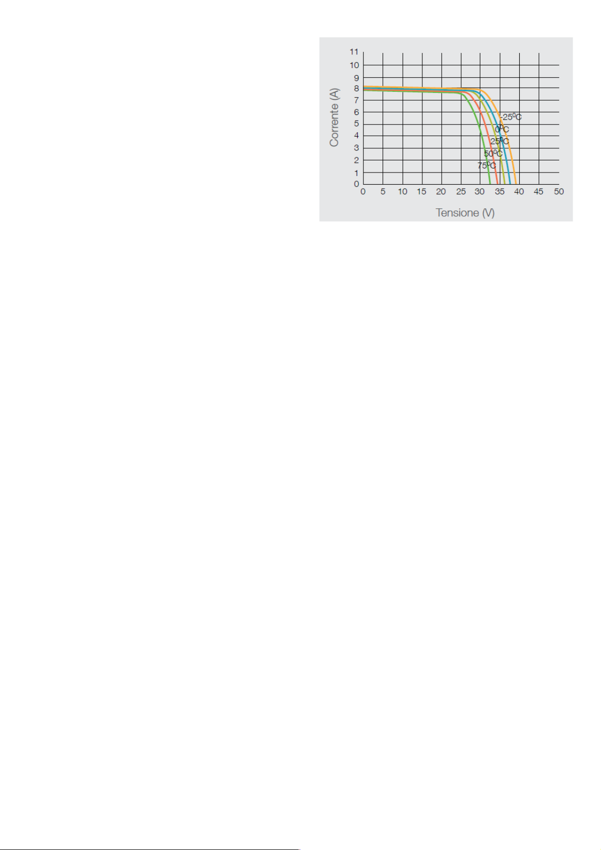
The general performance of the modules is heavily
dependent on the intensity of the incident solar
radiation, as illustrated in Fig.1. Acheiving
maximum performance requires proper
installation, with the modules oriented towards the
South and their surface exposed as
perpendicularly possible to the incident rays of the
sun; furthermore, avoiding any shading caused by
obstacles in and around the area of installation.
with tolerance of ± 3%
max)
Fig. 1: IV curve at different irradiance
A high ambient temperature and therefore, an
increased operational temperature of the modules,
also contribute to a proportional reduction in
electrical performance.
In order to optimize the production of electical
energy of the modules, and therefore of the system
connected to an electrical grid, it is the
responsibility of the installer to make sure the
modules are positioned as much as possible facing
south, with the tilt angle (β) (inclination of the
surface of the modules in respect to the ground, as
shown in Fig.2) optimal for the type of desired
application.
The tilt angle of ideal average throughout Italy is β
= 30°; however, even the inclination typical the roof
of a dwelling (β = 15-20°), being already an inclined
plane, could make the angle acceptable, if not
ideal, for the installation of coplanar modules on it
(using a special standard structure for support).
Depending on the variation of the tilt angle of the
modules with respect to the ground, or of their
orientation in relation to facing south (Azimuth),
there will be changes in the annual average
amount of energy produced by the modules
themselves, and therefore, of the plant connected
to the network to which they are linked.
FuturaSun srl – The specifications in this manual are subject to revisions without further notice
3
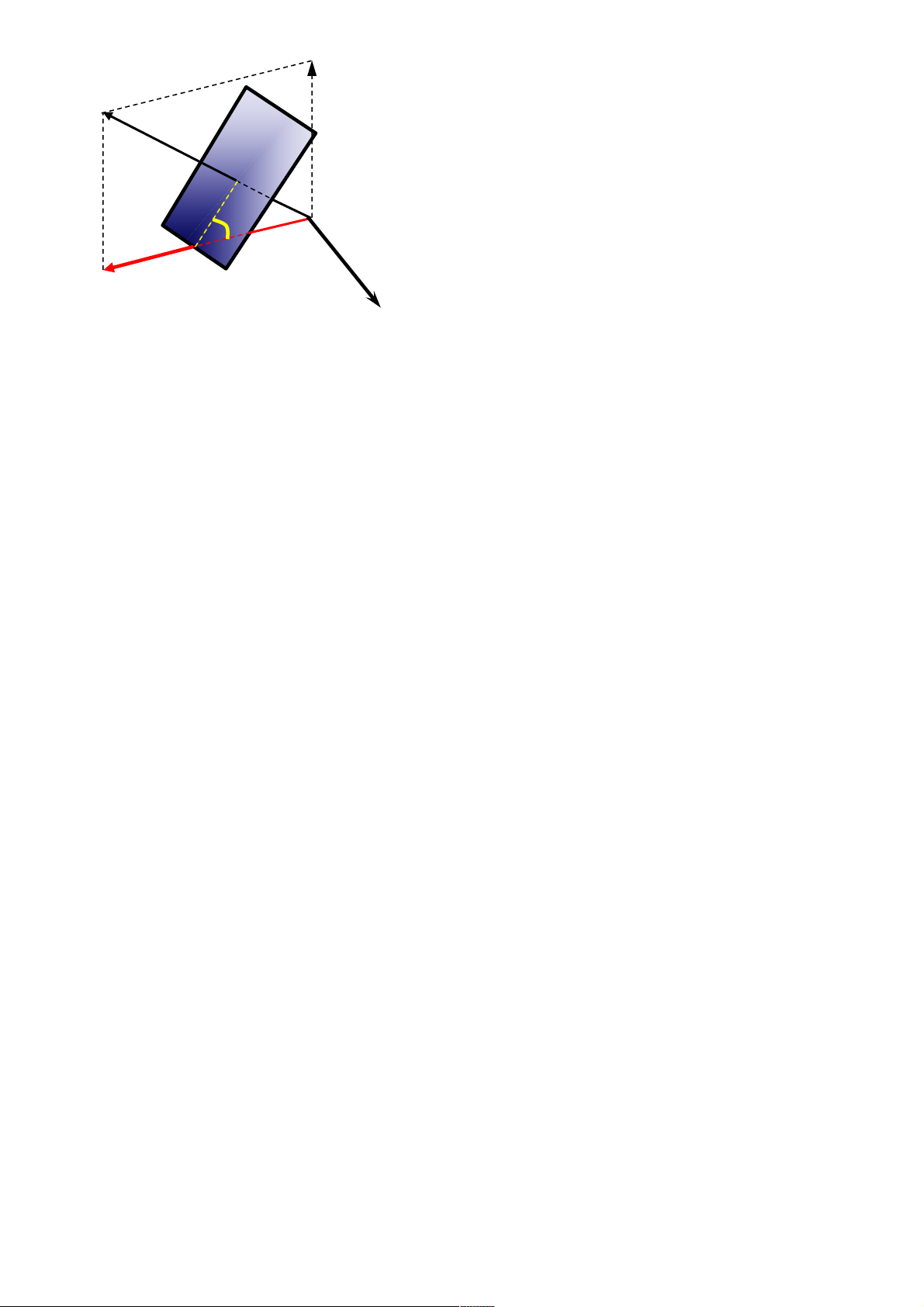
Fig. 2: Orientation Vs. Azimuth
East
b
South
2. Disclaimer of Liability
Since the methods of system design, installation
techniques, handling and use of this product are
beyond company control; FUTURASUN does not
assume responsibility and expressly disclaims
liability, for loss, damage or expense resulting from
improper installation, handling or use.
3. IEC 61215 & 61730 certifications
This product meets or exceeds the requirements
set forth by IEC 61215 and 61730 for PV Modules.
These standards cover flat-plate PV modules and
panels intended for installation on buildings or
those intended to be freestanding. This product is
not intended for use where artificially concentrated
sunlight is applied to the module.
4. Limited Warranty
Please refer to FUTURASUN General Terms and
Conditions of Sale for details of the modules’
limited warranty. Failure to comply with this Safety
and Installation Manual will invalidate
FUTURASUN Warranty for the PV modules as
stated in the General Terms and Conditions of
Sale.
5. Module Specification
Please refer to the technical datasheet for the
module FUTURASUN FU XXX respectively for
electrical performance data. These electrical data
are measured under Standard Test Conditions
(STC) of 1000 W/m2 irradiance, with Air Mass (AM)
of 1.5 spectrum, and a cell temperature of 25°C.
6. Safety Precautions
Installation should be performed only by
authorized personnel!
• Module installation must be performed in
compliance with the latest IEC code (CEI in
Italy)
• Within the modules, there are no user
serviceable parts. Do not attempt to repair any
part of the modules. Contact your module
supplier if maintenance is necessary
• In order to reduce the risk of electric shock,
prior to installing the modules, remove metallic
jewelry and use insulated tools during
installation.
• Do not expose the modules to artificially
concentrated sunlight!
• Do not stand on, drop, scratch, or allow objects
to fall on the modules.
• Do not lift the modules at the connectors or
junction box!
• Do not install or handle the modules when they
are wet or during periods of high winds.
• Do not use oil-based lubricants on any part of
the junction box as this can cause long-term
damage to the plastics.
• Ensure that wire cable connections are routed
in accordance with the junction box
manufacturer’s recommendations. Incorrect
routing of the wire cable can lead to stress
damage to the junction box.
• The minimum cable diameter for the modules
intended for field wiring is 4 mm².
• The PV connectors to mate with the modules
should be MC4 compatible and qualified
according to IEC 62852.
The rated voltage of the connector should be
1500 V and the rated current ≥ 30 A.
The cross section for the connector is 1 x 4,0
mm².
• Do not leave cable connectors exposed in
adverse climatic conditions. Water and dust
deposits inside the cable connectors can cause
long-term damage.
• Broken module glass, a torn back sheet, a
broken junction box or broken connectors are
electrical safety hazards; consequently,
contact with a damaged module can cause
electric shock.
• The total voltage of modules connected in
series corresponds to the sum of the voltages
of the single modules; whereas connecting the
modules in parallel results in adding up the
currents. Consequently, strings of interconnected modules can produce high voltages
and high currents and constitute an increased
risk of electric shock and may cause injury or
death.
• For installation, maintenance, or before making
any electrical connection or disconnection,
ensure all modules in the PV array are
exposed to a light intensity that is less than
400 W/m2!! If necessary, the modules should
be covered with an opaque cloth or other
material in order to shield them from exposure
to light intensity greater than 400 W/m2.
FuturaSun srl – The specifications in this manual are subject to revisions without further notice
4
 Loading...