

Page 1

MCB3 CONTROL BOX
Installation Manual
Technical Information
Software Version 3.00
P/N ATI-026046 Rev C
Page 2

1.1
Amendments / Updates
All updated or amended information will be forwarded as it becomes available.
The information contained below identies pages or drawings that have been revised.
Section Page, Software or
Drawing Number
S/W V2.00 Added: Italian, Spanish, French languages to
S/W V3.00 Added Troubleshoot Menu; added laser strike
1.2
Description Revision Date
operation text; Data Transfer function; mm & cm
units; contrast limit;
Revised Slope Reverse and Reference elevation
icons.
requirements to LS Aux. valve function logic.
Added single toggle remote switches with LH/RH
mounting polarity.
Contact Information
B June 2007
C Sept 2007
Futtura Tools & Technologies, Inc.
100 N Rockwell Ste 96
Oklahoma City, OK 73127 USA
Phone: (877) 399-9900
Fax: (405) 470-1772
Website: www.futturaus.com
Email: sales@futturaus.com
MCB3 Installation ManualPage ii
Page 3

1.3
Introduction
Table of Contents
SECTION 1: Introduction
1.1 Amendments / Updates .....................................................................ii
1.2 Contact Information ...........................................................................ii
1.3 Table of Contents .............................................................................. 1
1.4 Disclaimer ......................................................................................... 3
1.5 Meaning of Symbols ......................................................................... 4
SECTION 2: General Information
2.1 System Description ........................................................................... 5
2.2 General Identication ........................................................................ 6
2.3 Specications ...................................................................................8
SECTION 3: Machine Architecture
3.1 Machinery ......................................................................................... 9
3.2 Mast Mounting Options ................................................................... 10
SECTION 4: General Installation
4.1 System Components ...................................................................... 13
4.2 Mast Installation .............................................................................. 15
4.3 System Wiring ................................................................................ 16
4.4 System Wiring Diagram .................................................................. 18
4.5 Cable Diagrams .............................................................................. 19
4.6 Cable Installation Notes .................................................................. 22
SECTION 5: Technical Setup Menus
5.1 Technical Setup Menu .................................................................... 23
5.2 Technical Setup Menu List .............................................................. 24
5.3 Installation Log ...............................................................................26
5.4 System Setup Menu ....................................................................... 27
5.5 Valve Setup Menu ..........................................................................31
5.6 Check System Performance ........................................................... 41
5.7 Custom Setup Menu ....................................................................... 42
5.8 Troubleshoot Menu ......................................................................... 44
5.9 Store / Recall Setups ...................................................................... 46
5.10 Data Transfer ................................................................................. 46
MCB3 Installation Manual Page 1
Page 4

Introduction
1.3
APPENDICES
A Valve Identication and Setting Recommendation ......................... 47
B Fault Codes .................................................................................... 48
C Hydraulic Valve Guide ..................................................................... 49
D Elevation Error caused by Slope On Grade Deadband .................. 52
E Upgrading the MCB3 Firmware ...................................................... 54
Table of Contents
MCB3 Installation ManualPage 2
Page 5

Introduction
1.4
Disclaimer
All documentation, data, dimensions, and drawings in this manual were compiled and checked
with great care, however Futtura Tools & Technologies, Inc. cannot assume responsibility for
possible errors or omissions. We reserve the right to change designs and specifications without
notice.
Futtura Tools & Technologies, Inc. accepts no liability whatsoever for direct or indirect damage
that may occur due to the unauthorized or improper use or interpretation of this document, and
also shall not be liable for direct or consequential damages resulting from the improper service,
application, maintenance or use of the product.
This document is strictly for the use of qualified service technicians with the requisite technical
skills, training, and facilities. This manual should be read completely before installing the
product.
Reproduction of any or all parts of this manual, including electronic, is prohibited without the
written permission of the Futtura Tools & Technologies, Inc. It also may not be used for any
purpose other than for which is was intended, nor made accessible or communicated in any
form to any third party not expressly authorized by Futtura Tools & Technologies, Inc.
June 2015
MCB3 Installation Manual
Page 3
Page 6
Introduction
WARNING: Indicates a potential hazardous situation, which could result in death or serious injury.
CAUTION: Indicates a potentially hazardous situation, which could result in a minor or moderate
injury and/or material, nancial, or environmental damage.
Meaning of Symbols1.5
NOTE: Important information to enable the product to
unrelated to safety.
NOTE: The installation technician should be a qualied person who is familiar with the installation,
construction, and operation of the machine and laser equipment and the hazards involved.
NOTE: The user of this product is expected to follow all operating and safety instructions of this manual
and of the machinery operator’s manual. Perform periodic checks of the product’s performance. The
manufacturer or its representatives assume no responsibility for results
including any direct, indirect, consequential damage, and loss of prots. Check your work frequently.
WARNING: High pressure uid is present in operational hydraulic systems. Fluids under high pressure
are dangerous and can cause serious injury or death. Do not make modications, repairs or adjust-
ments to any hydraulic system unless you are competent or working under competent supervision. If
in doubt consult a qualied technician or engineer.
WARNING: When working near construction or agricultural machinery, follow all safety precautions
as described in the machinery’s user manual.
machine before operating or beginning any work.
WARNING: Do not remove the back panel of the control box. The back panel is to be accessed by
authorized Futtura Tools & Technologies service personnel only.
WARNING: Be aware of all overhead obstructions and electrical power lines. The receiver and mast
may be higher than the machinery. Remove when transporting.
Familiarize yourself with all basic functions of the
be used in a correct and efcient manner
of the use of this product
WARNING: When excavating or trenching, follow all excavation and trench safety regulations and
practices.
CAUTION: Do not disassemble any part of the receiver other than to replace batteries. The receiver
is to be serviced by authorized Futtura Tools & Technologies service personnel only.
CAUTION: Ensure all equipment is properly installed, the MCR receiver is secured in its
mounting position, and all cables connections are tight and secure.
NOTE: Environmental Limits: Suitable for use in an atmosphere appropriate for human habitation (no
protection in an aggressive or explosive environment).
MCB3 Installation ManualPage 4
Page 7

General Information
2.1 System Description
The Dual Automatic Blade Control System uses a MCB3 Control Box, MCR laser
receivers, cables, optional remote switches, and a hydraulic kit to automatically control
construction grading machinery for earthmoving and grading applications.
Reference elevation from a rotating laser is received by the MCR receiver and sent to the
control box. The information is processed and automatically directs the hydraulic valves to maintain
the elevation of the blade when in automatic mode.
System conguration can be set for lift and tilt control - a typical bulldozer conguration.
Conguration can also be lift and lift - a typical motor grader conguration. In addition the system
can be set to control the elevation of two independent implements with receivers, a typical tandem
carry-all type scraper conguration
Elevation control may be used in conjunction with slope control with certain MCR receivers
that contain internal slope sensors. These slope sensors control the slope of the blade relative to
the machine. Slope lasers provide a slope relative to the laser transmitter.
MCB3 Installation Manual Page 5
Page 8
General Information
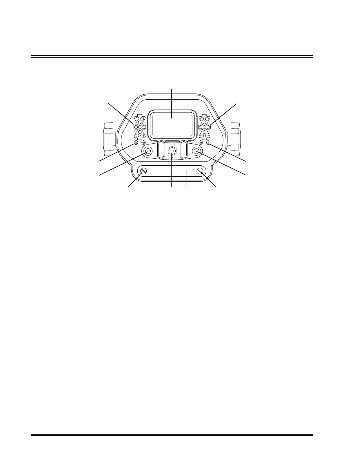
2.2 General Identication
1
3
10
11
9
6
7
68
2
3
4
5
1. Liquid Crystal Display (LCD) - indicates control modes, guidance information and system status.
Menus are displayed during setup.
2. Right Grade LED's - green bar indicates on-grade, red arrows indicate direction to grade for
right side. Blinking red arrows indicate lost beam and direction to move to nd beam.
3. Mounting Knob - secures to control box bracket.
4. Right Auto/Manual LED's - green "A" indicates Automatic or amber "M" indicates Manual is
selected on right side.
5. Right Multi-Switch - Left/right movement selects Auto/Manual control and up/down movement
enables Raise/Lower implement. Rotation increases/decreases the control set point. Pressing in
enables elevation or slope matching. Navigates User Setup menu.
6. Access panel thumbscrew.
7. Access panel cover plate - panel contains rotary switch, DIP switch and fuse. DIP switch used
for installation.
8. Power / Setup Switch - turns power on and off. Toggle switch upward (I i) to turn power on.
Toggle switch downward (o) to turn power off. Enables changing operating modes and entry into
User Setup modes. Enables entry into Help screens.
9. Left Multi-Switch - Left/right movement selects Auto/Manual control and up/down movement
enables Raise/Lower implement. Rotation increases/decreases elevation. Pressing in enables
elevation or slope matching. Navigates User Setup menu.
10. Left Auto/Manual LED's - green "A" indicates Automatic or amber "M" indicates Manual is
selected on left side.
11. Left Grade LED's - green bar indicates on grade, red arrows indicate direction to grade for left
side. Blinking red arrows indicate lost beam and the direction to move to nd beam.
MCB3 Installation ManualPage 6
Page 9
General Information
2.2
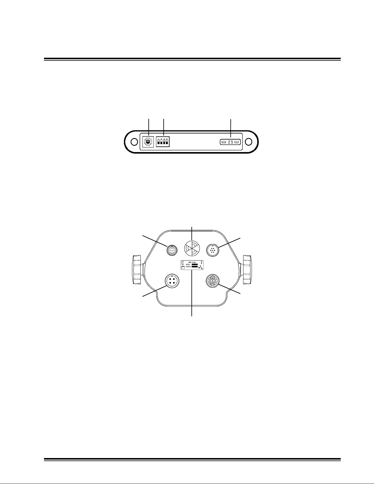
General Identication
12 13
14
12. Rotary Switch - used for factory tests. Default position is 0.
13. DIP Switch - used for installation. Default position is all switch bats down (off).
14. Fuse - 25 amp, auto style.
19
18
15
17
20
16
15. 7-pin connector - optional remote switch.
16. 10-socket connector - hydraulic valve output.
17. 4-pin connector - machine power input.
18. 7-socket connector - MCR receiver communication.
19. Beeper with adjustable volume control - rotate to increase or decrease volume. Single beep
is activated when switch command is accepted. Double beep activated when switch command
is not available, incorrect or not accepted.
20. Identication / serial number label / cable function symbols.
Refer to the control box operator's manual (P/N ATI-010884) for detailed operational information.
MCB3 Installation Manual Page 7
Page 10

General Information
2.3
Specications
0&B Dual Control Box
Grade Display Green On-Grade LED's
Red High / Low LED's
Display LCD
Operating Voltage 10 to 30 Volts DC, reverse polarity protected
Maximum Current 5 Amps per driver
Electrical Connection Standard military type
Valve Compatibility PT, Proportional Time (On/Off),
PC, Proportional Current, and
PV, Proportional Voltage
Laser Receiver Deadband 0 - 2.0 inches (0.05 in increments)
0 - 0.16 ft (0.005 ft increments)
0 - 50 mm (1.0 mm increments)
BE3+ 0 - 1.0 inches
0 - 0.08 ft
0 - 25 mm
Slope Set Point Range +/- 23 degrees (+/- 44%)
Remote Switch Option Raise/Lower, Auto/Manual Multi-Switch
Single switch for lift & tilt
Dual switches for dual lift
Weight 5 lbs. (2.25 kg)
Dimensions (without knobs) 7.7 x 5.5 x 5.5 in. (196 x 140 x 140 mm)
Operating Temperature -4° F to 140° F (-20° C to +60° C)
*Specicationssubjecttochangewithoutnotice
MCB3 Installation ManualPage 8
Page 11
Machine Architecture
3.1
Machine Architecture
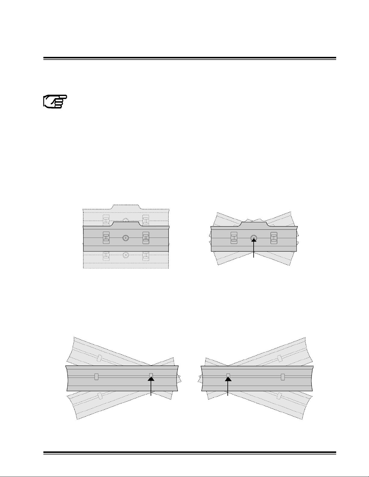
NOTE: The left and right sides of the machine are referenced while seated in the
operator's seat, facing the normal direction of travel. Graphics are depicted from the
operator's point of view.
Machine architecture is referenced by what type of cylinder arrangement controls the blade - Lift &
Tilt or Lift & Lift.
Left side and right side are dened as the operator would view the system when facing forward in
the operators seat.
Lift & Tilt is a common dozer arrangement. Typically for a bulldozer, one set of cylinders are linked
together for blade lift. A separate circuit controls blade tilt which pivots about a single pivot point.
Lift & Tilt is not conned to bulldozers. Skid steer attachments and other tractor attachments may
operate as a Lift & Tilt system. These systems may use a single lift cylinder.
Pivot Point
Blade Lift
Blade Tilt
Lift & Lift is a common motorgrader arrangement. A separate cylinder controls each side for
blade lift which pivots about a point on the opposite end of the blade. Lift & Lift is not conned
to motorgraders. Tractor attachments such as drag boxes may operate as a Lift & Lift system.
Additionally tandem pulled behind scrapers can operate as two independent lift systems.
Pivot Point
Left Hand Side Lift
Pivot Point
Right Hand Side Lift
MCB3 Installation Manual Page 9
Page 12
Machine Architecture
3.2
Mast Mounting Options
Mast mounting locations may differ depending on machine architecture, receiver model, type of
machine, etc.
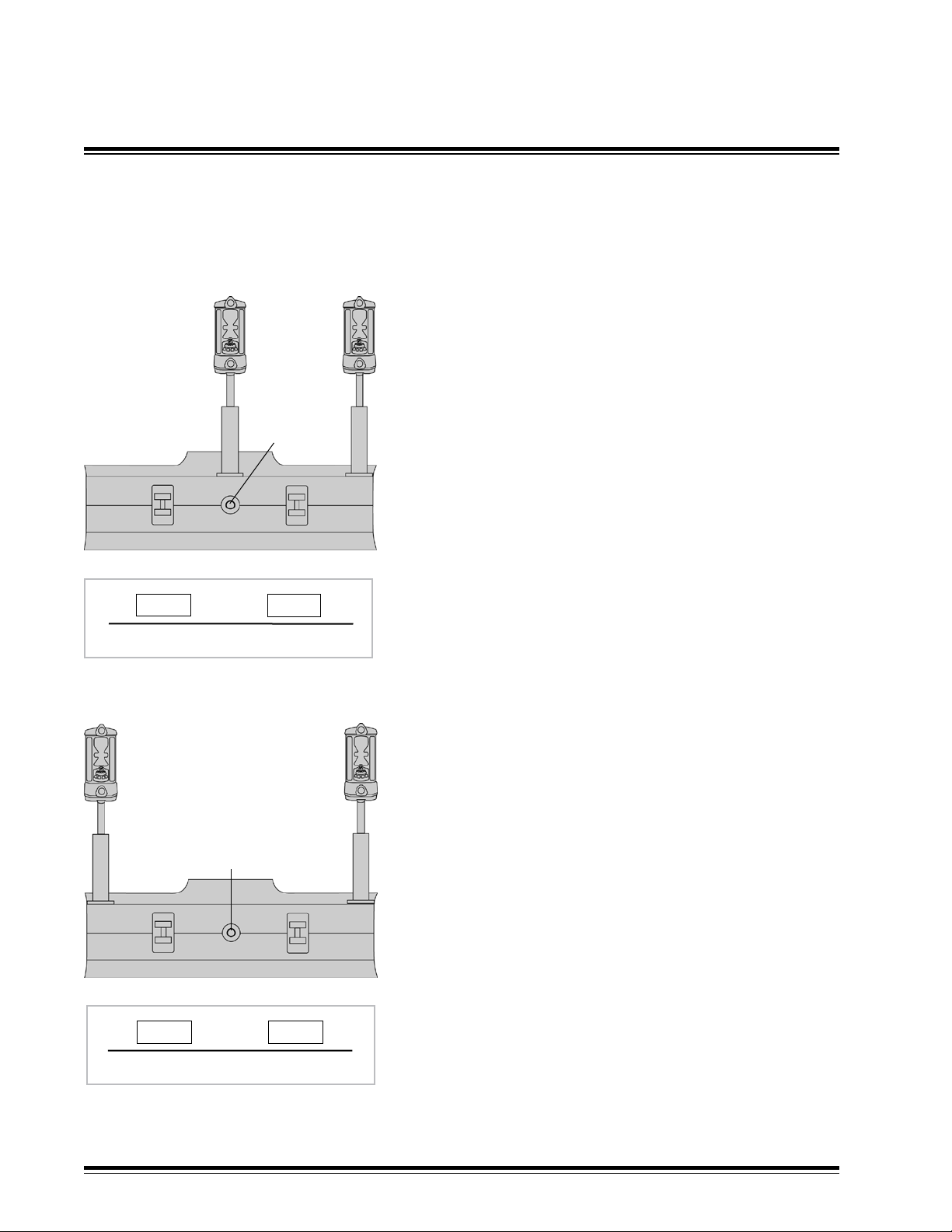
Lift & Tilt: Traditional mounting
The traditional method for mounting dual receivers is to
mount the Lift mast and receiver (1) in the center of the
1
3
blade above the blade pivot point (2) and the Tilt mast
and receiver (3) on the end of the right hand side of the
2
blade.
NOTE: Without cross-coupling, a Lift error will cause an
unneeded Tilt correction which leads to instability (duckwalking). Traditional systems slow down the tilt blade
speed to remain stable.
Turn on and set up the cross coupling to minimize the
instability and improve performance. When the cross
coupling is set, the Tilt can be ran as fast as the lift and
00.00 38.00
V
XX
remain stable.
Refer to the cross coupling menus in System Setup § 5.4.
Cross Coupling Setup Example
1
2
37.75 38.00
V
Cross Coupling Setup Example
Lift & Tilt: Wide Stance mounting option
The grade accuracy at the end of the blade can be
increased by moving the lift receiver (1) and the tilt
3
receiver (3) to each end of the blade. Refer to the
diagram on the following page for an illustration.
Cross coupling must be turned on. Refer to the cross
coupling menus in System Setup § 5.4.
The wide stance also avoids mast mounting near blade
king pin and linkage.
For low mounted receivers, it places the receiver grade
display in better line of sight to the corners of the blade.
This arrangement is not recommended for single laser
receiver or internal slope sensor systems.
XX
MCB3 Installation ManualPage 10
Page 13
Machine Architecture
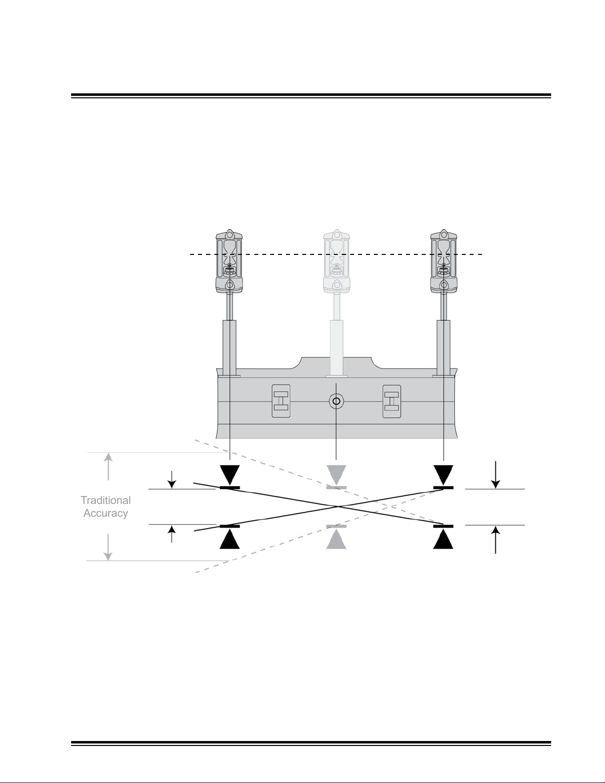
Traditional
Accuracy
3.2
Lift & Tilt: Wide Stance option accuracy comparison.
Increasing the distance between the two receivers decreases the allowable movement within the
deadbands before a correction takes place.
Laser
Mast Mounting Options
Wide Stance
Accuracy
MCB3 Installation Manual Page 11
On-grade
Deadband
Page 14
Machine Architecture
3.2
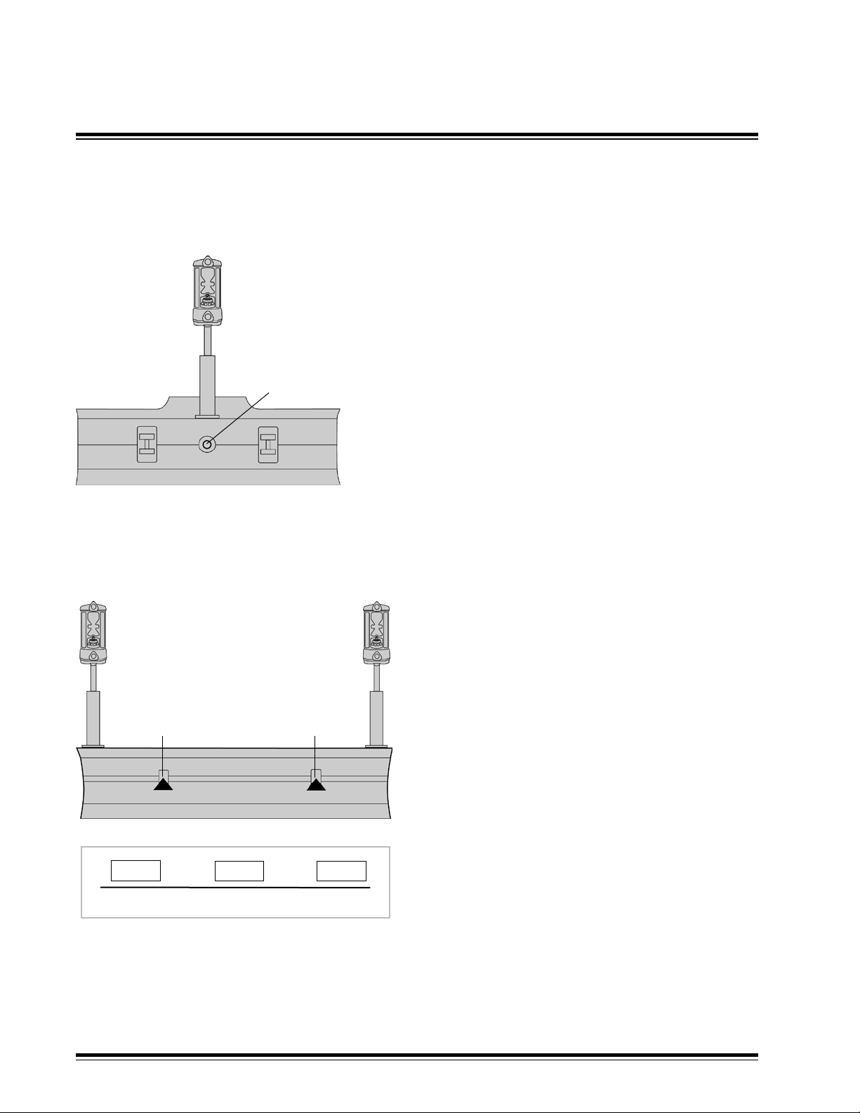
Lift & Tilt: Single Laser Receiver
1
2
Lift & Lift: Dual Laser Receivers
Mast Mounting Options
When a single laser receiver (1) is used, it is best to
mount it above the blade's pivot point (2).
The internal slope sensor of a MCR2 or
MCR3 may be used to control the tilt of the
blade.
A slope sensor driven tilt control will run slower than a
laser receiver driven tilt control. See § 5.5.
Cross Coupling is not required.
1
20.25
2
45.50 20.00
V
Cross Coupling Setup Example
V
Mount the left hand receiver (1) near the left hand
end of the blade.
Mount the right hand receiver (4) near the right
hand end of the blade.
4
3
Cross coupling must be turned on and setup.
Mounting receivers near the end of the blade
provides the best accuracy.
Mounting receivers near the blade pivot points
(2 & 3) provides the best stability.
Mounting locations are usually dictated by the
machine geometry.
If slope control is used, blade speeds must be
lowered compared to laser control. See § 5.5.
XX
MCB3 Installation ManualPage 12
Page 15

General Installation
4.1
Control Box
The control box mounts in the cab and is cable connected to machine power, the MCR
receivers and the hydraulic valve. Optional remote switches may also be connected. The operator
adjusts and selects various options using toggle switches or multi-switches that move left/right,
up/down, rotate in both directions, and can be pushed in.
An LCD indicates system and conguration status. An LED display indicates grade information for
each side. Automatic or manual modes are also indicated with LED's for each side.
Refer to the control box operator's manual (P/N ATI-010884) for detailed operational information.
The Control Box should be mounted in a location that is easily visible to the operator, is within easy
reach of the operator’s hands, and can be easily installed and removed. Insure that the location does
not interfere with other machine controls or operator movements. Remote switches are available which
allow the operator to adjust the system while keeping hands on the machine controls.
The Control Box has vented drain holes on the rear bottom of the unit that must
face downward.
A control box mounting bracket (ATI-950054) is designed to accept the mounting
knobs that are included with the control box.
System Components
0&5 Receivers
All MCR receivers feature 360 degree laser reception and work with all common rotating lasers.
MCR models 1, 2, MC2E, and 3 are designed for automatic blade control and will work with
the MCB3. The model 1 has limited proportional control capability and therefore limited on-grade
offset and elevation matching capability.
Models 2 and 3 incorporate internal slope sensors that can be used for blade slope control.
NOTE: These slope sensors must be calibrated to the machine before use.
Models 1, 2 and 3 can also be used as stand alone display receivers.
Please refer to the specic MCR operator's manuals for more detailed information.
The MCR receivers mount to round masts from sizes 1.66” to 2.00” O.D. (42 to 50 mm) and to
1-1/2” (38 mm) square tube.
The communication protocol for the MCR receivers is proprietary RS485 @ 62.5 kbaud.
MCB3 Installation Manual Page 13
Page 16

General Installation
4.1
Hydraulic Valves:
The Control Box supports Proportional Time (PT), Proportional Current (PC), and Proportional Voltage
(PV) hydraulic valves.
Hydraulic installation kits are available for several common machines and depict valve mounting. Some
kits contain the hydraulic valves, valve brackets, hydraulic hoses and ttings necessary for automatic
control of a specic machine. Other valve kits require some additional components to be supplied.
A separate installation guide is included with the hydraulic kit.
STM1 Mast:
The Model STM1 shock mounted manually telescoping mast allows the receiver to be positioned
above the machinery for unobstructed laser reception.
STM1 Specications
Height retracted: 75.5 in. (192 cm)
Extension Length 48.0 in. (122 cm)
Tape increments 1/16th in. and 1 mm
Weight 52 lbs. (23.6 kg)
System Components
Bolt size 3/4 in x 10 x 2-1/2 in Grade 8
MCB3 Installation ManualPage 14
Page 17
General Installation
4.2
STM1 Mast Installation:
The machine should be positioned on a at level surface with the blade on the ground. Make sure
that all mast-mounting bolts are accessible with the appropriate tools when the mounting assembly
is complete.
Caution: Before welding turn the master disconnect off and disconnect any computer module.
1. Observe all safety practices recommenced by the machinery manufacturer while installing and
using the mast.
a) Turn off engine and engage parking brake.
b) Rest blade on the ground.
c) Take precautions to avoid lifting or falling injuries. Mast weight is
57 Lbs. (26 kg.)
2. To minimize elevation errors due to changing cut depths:
a)
The masts should be positioned to place the laser receive
close as possible vertically over the cutting edge of the blade.
b) The masts should be vertical "front-to-back" when the blade is in
its normal operating position.
3. To minimize elevation errors due to changing blade tilt, the masts
should be vertical "side-to-side" when the blade is in its normal
operating position.
System Components
rs as
4. Weld the optional mast mounting plates (ATI-010766) to best meet
the above recommendations, and:
a) Not interfere with blade movement or linkages.
b) Provide clearance for pin removal, or other service
requirements.
c) Follow all machine manufacturer precautions for welding to the
machine.
d) Several pieces of material are usually required to stand the plates
slightly above a dozer blade. These pieces are not included with the
mounting plate.
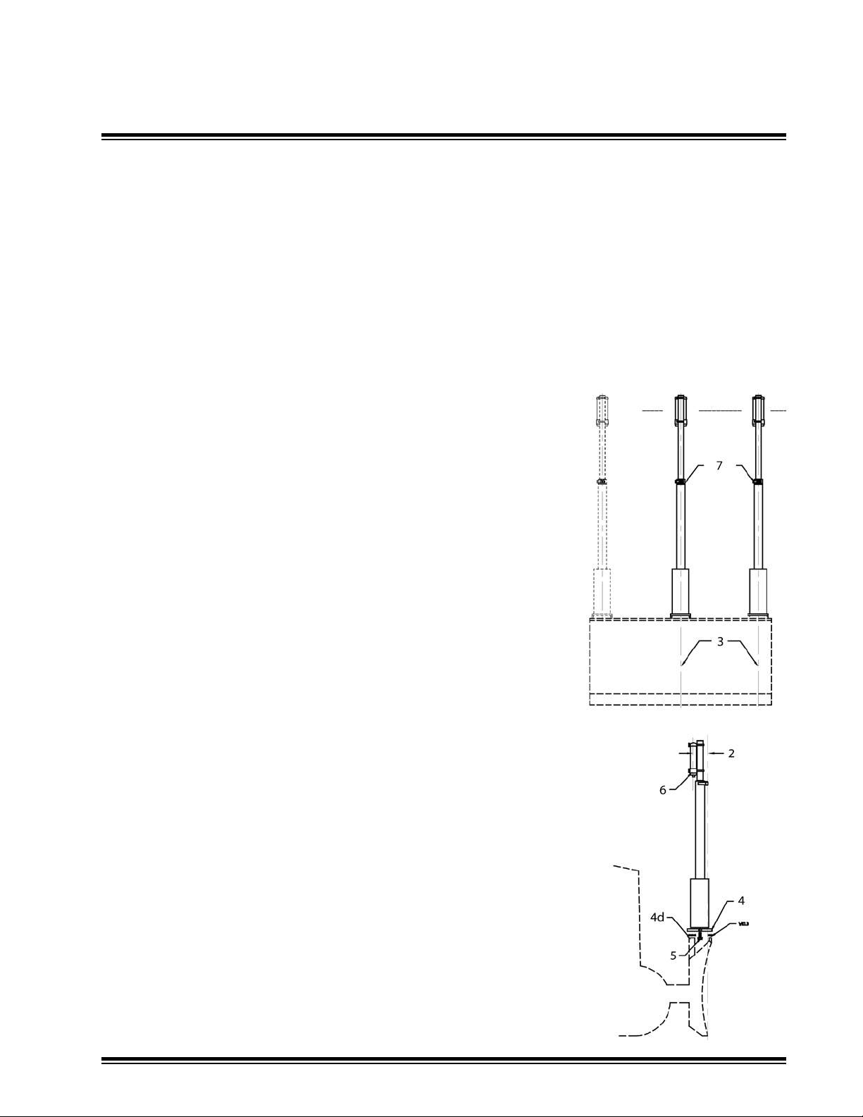
5. Attach the masts to the mounting plates with provided (1) 3/4-10
x 2-1/2 inch long grade 8 screws and lock washers. Torque to 265
ft-lbs. (37 mkg)
6. Attach the laser receivers to the masts as shown. Wrap the
electrical cable around the masts to keep it out of harm from blade
linkages or material near the blade. Attach the cables to the laser
receivers.
7. Loosen the mast clamp and extend the mast to the desired
elevation to clear laser obstructions such as the machine's cab.
Tighten the mast clamp.
a) Pull out on the clamp handle to reposition the handle.
Operator's View
MCB3 Installation Manual Page 15
Page 18

General Installation
4.3
System Wiring
Cables are generally shipped at a predetermined length required for a particular machine. Connectors
are installed at the factory.
Plan the routing of all cables prior to actual installation. Some machines may require cutting a
hole in the sheet metal with a hole saw to route the cable. Be sure not to drill into harnesses or other
components. Grind or le any sharp edges and add edge grommet or wire loom to protect the cables.
All cables should be attached to the machine at a minimum of every 2 to 3 feet (.6 to 1.0 meter)
or less to try to eliminate cable movement and possible abrasion damage. Special care should be
taken at ex points to ensure the cable moves freely and does not rub on other hoses, ttings, or
the machine. Provide
cables should not
adequate cable length to avoid pinching, stretching, and tight bending
be clamped to pipes or hoses that will cause the cable to b
e exposed to high
. Also,
temperatures.
Power Cable:
Connect the 4-socket connector on the power cable to the 4-pin
connector on the box. Route the
cable to the machine's battery and connect the terminal ends to the battery. The red terminal is for the
positive post and the black is for ground. The box has reverse polarity protection in case the terminals
are connected improperly.
NOTE: In order to utilize the machine's master disconnect, the ground wire must be
connected to the machine frame.
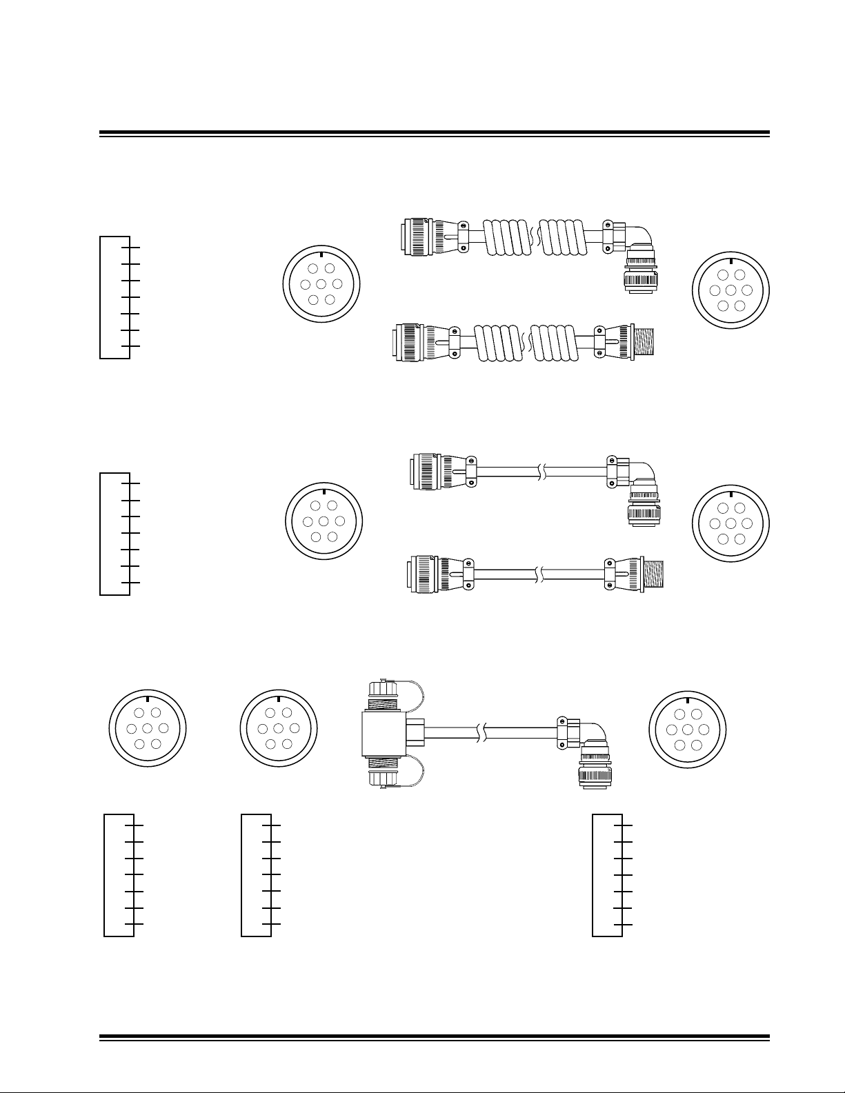
Receiver Cable:
A dual receiver cable connects the control box with a dual connector junction block that supports two
laser receivers. Two separate cables connect the junction block to the receivers.
The junction block can be mounted on the front of the machine with the provided 1/4 inch hardware.
Once the junction block mounting is determined, route the cable through the machine to the control
box. Connect the cable 7-pin connector to the 7-socket connector on the control box.
The junction block is marked "L" for left side and "R" for right side as the operator is looking forward
in the direction of machine travel.
Connect the receiver straight cable or coil cord 7-pin connector to the 7-socket connector on the junction
block for each side. Connect the cable's 7-socket connector to the 7-pin connector on the bottom of
the MCR receiver for each side.
Attach dust caps to connectors when not in use.
Dual Receiver Cable - Hood Mounting
Lay block on its side with bolt holes vertical. Mount to top of
hood with provided hardware.
Alternatively, the junction block may be mounted to the grill
(possibly with minor grill modications) and user provided
hardware.
MCB3 Installation ManualPage 16
Page 19

General Installation
4.3
Valve Cable:
Connect the 10-pin valve cable to the 10-socket connector on the box. Route the cable to the valves.
Connect the open-ended wires to the valve according to the cable diagrams in § 3.4.
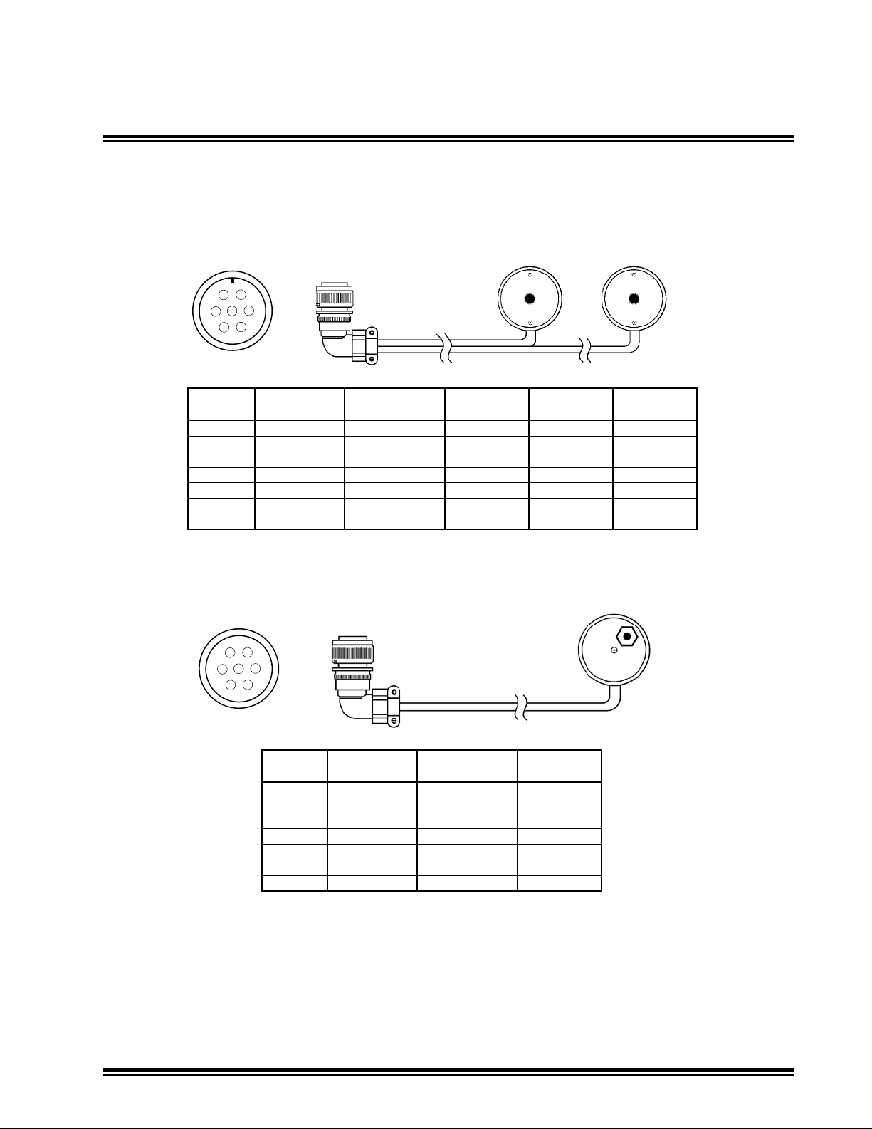
Optional Remote Switch:
A single remote switch is used for Lift and Tilt applications. A dual remote switch is used for Dual Lift
applications.
Multi-switch remote cables (P/N ATI-010904-XX and ATI-010938-XX) can be congured to operate
similar to the multi-switches on the control box. Typically the remote switches are used to select
automatic or manual control. Raise or lower implement may be selected, as well as elevation offset
and grade matching functions. Refer to System Setup § 5.4
The multi-switch remotes are congured with the cable at the bottom when mounted and the switch
facing inward so the thumb activates the switch. When mounted and congured properly, forward is
Automatic, backward is Manual, up is Raise, and down is Lower.
Separate toggle switch remote cables are available and can be congured for automatic / manual
(P/N ATI-011012-XX) and raise / lower.
System Wiring
1. The remote switch assembly is designed to mount to lever shafts from 3/8" to 1-1/8" in.
(10 to 28 mm)
2. Determine remote switch mounting location for easy access during operation. Cable should route
downward from switch housing.
3. If mounted to a moving lever, ensure there is enough cable to permit full lever travel.
4. Remove any dirt or oils from the area where the switch will mount with isopropyl alcohol or
detergent cleaner.
5. Remove the adhesive liners on the double sticky
tape and apply the switch.
6. Select the correct length of screw for the shaft
diameter ad tighten clamping screws. Do not
overtighten as this can distort housing and clamp.
7. Strain relief the cable by tie wrapping it to the lever
as shown.
8. Assign and check the functions with the control box.
diameter by using the different screws provided.
Switch Orientation
MCB3 Installation Manual Page 17
Page 20

General Installation
MCR
2, MC2E, 3
7 SOC
System Wiring Diagram4.4
MCR
2, MC2E, 3
10
or
7 PIN
7 SOC
5
4
or
7 PIN
6
or
7 PIN
Extensions
L
7 SOC
11
7 PIN
7 SOC
4
6
R
7 SOC
5
or
or
7 PIN
Single Multi-Switch
Remote Switch
7
Dual Multi-Switch
Remote Switch
or
Single Toggle A/M
Remote Switch
or
8
9
3
7 PIN
4 SOC
2
7 SOC
4 PIN
Control Box
7 PIN
10 SOC
7 SOC
10 PIN
1
MCB3
Master
Disconnect
Switch
+
10 - 30 VDC
10 - 30V DC
_
Dual PV
Valve
Dual PC or PT
Valve
Item Part No. Description
1 ATI-026044-XX Dual PT/PC/PV Valve Cable
2 ATI-024012-XX Power Cable
3 ATI-010907-XX Dual Receiver Cable w/ Junction Block
4 ATI-026047 Receiver Coil Cord, CB5X, 4-16 ft (1.2 - 4.9 m)
5 ATI-010980-XX Straight Receiver Cable
6 ATI-026045 Receiver Coil Cord, CB5X, 3-12 ft (0.9 - 3.7 m)
7 ATI-010904-XX Single Remote Multi-Switch Cable, CB5X
8 ATI-010938-XX Dual Remote Multi-Switch Cable, CB5X
9 ATI-011012-XX Single Remote A/M Toggle Switch, CB5X
10 ATI-026026-XX Straight Cable Extension
11 ATI-010975 Coil Cord Extension 3-12 ft (0.9 - 3.7 m)
MCB3 Installation ManualPage 18
Page 21
Red - Power
A
Green - Data -
B
White - Data +
C
Black - Ground
D
Orange - N/U
E
Blue - N/U
F
N/C
G
Red - Power
A
Green - Data -
B
White - Data +
C
Black - Ground
D
N/C
E
N/C
F
N/C
G
A
F
E
G
B
D
C
7-Socket
A
F
E
G
B
D
C
7-Socket
General Installation
Cable Diagrams4.5
A
Receiver Coil Cord
ATI-026045
Receiver Coil Cord Extension
ATI-010975
Receiver Straight Cable
ATI-010980-XX
F
G
E
D
7-Pin
F
G
E
D
7-Pin
B
C
A
B
C
A
B
C
D
E
F
G
A
B
C
F
E
G
D
Orange
Green
White
Black
N/C
N/C
N/C
Straight Cable Extension
ATI-026026-XX
A
F
E
G
B
D
C
Left 7-SocketRight 7-Socket
Red
A
Green
B
White
C
Black
D
N/C
E
N/C
F
N/C
G
Note: -XX represents cable length in feet
N/C - Not Connected
N/U - Not Used
R
L
Dual Receiver Cable
with Junction Block
ATI-010907
Red - Left Power
A
Green - Data -
B
White - Data +
C
Black - Ground
D
N/C
E
N/C
F
Orange - Right Power
G
F
G
E
D
7-Pin
A
B
C
MCB3 Installation Manual Page 19
Page 22

General Installation
4.5
Black - Ground
A
White - Ground
B
Red - Power
C
Green - Power
D
Cable Diagrams
A
D
B
C
4-Socket
A
H
I
B
G
J
C
F
D
E
10-Pin
Connector Wire PC / PC Valve Valve Hirschmann
10 Pin Color Function Function Pin
A Blue LH Lower LH Fault 3
B Green LH Raise RH Fault 3
C Red *SwPower *LH Sw Power 1
D Orange *LoadSense *RH Sw Power 1
E White Not Used LH Raise/Lower 2
F Brown RH Raise Not Used G Yellow RH Lower Not Used H Violet Not Used RH Raise/Lower 2
I Black Ground Ground Ground
J Gray Ground Ground Ground
Dual Valve Cable
PT/PC/PV
ATI-026044-XX
PT / PT or PV / PV PV / PV Valve
Power Cable
ATI-024012-XX
Note: *Function selected in Auxiliary Valve Driver Setup
Refer to Valve Setup § 5.5
Singe Multi-Switch
Remote Switch Cable
ATI-010904-XX
A
F
E
G
B
D
C
7-Socket
Connector Wire LH Remote
7 Pin Color Function Switch PCB
A Orange LH Analog In J2
B N/C RH Analog in N/C
C Black LH Phase A J3
D White LH Phase B J4
E N/C RH Phase A N/C
F Red Rem Sw Power J1
G N/C RH Phase B N/C
M
R
A
L
MCB3 Installation ManualPage 20
Page 23
General Installation
4.5
Cable Diagrams
Dual Multi-Switch
Remote Switch Cable
ATI-010938-XX
A
F
E
G
B
D
C
7-Socket
Connector LH LH Remote RH RH Remote
7 Pin Function Cable Color Switch PCB Cable Color Switch PCB
A LH Analog In Orange J2 N/C N/C
B RH Analog in N/C N/C Orange J2
C LH Phase A Black J3 N/C N/C
D LH Phase B White J4 N/C N/C
E RH Phase A N/C N/C Blue J3
F Rem Sw Power Red J1 Red J1
G RH Phase B N/C N/C Green J4
R
AM
L
R
A M
L
RHLH
Single Remote A/M Toggle
Switch Cable
A
F
E
G
B
D
C
7-Socket
Connector Wire
7 Pin Color Function
A Orange LH Auto/Manual
B Green LH Raise/Lower N/C
C Blue RH Auto/Manual N/C
D White RH Raise/Lower N/C
E N/C
F Red Rem Sw Power
G Black Rem Sw Ground
NOTE: Remote Switches are congured with the cable routed downward from the switch housing.
Automatic selection is multi-switch forward. Manual is multi-switch back.
NOTE: -XX represents cable length in feet R - Raise A - Automatic
N/C - Not Connected L - Lower M - Manual
N/U - Not Used RH - Right Hand
LH - Left Hand
ATI-011012-XX
AM
MCB3 Installation Manual Page 21
Page 24
General Installation
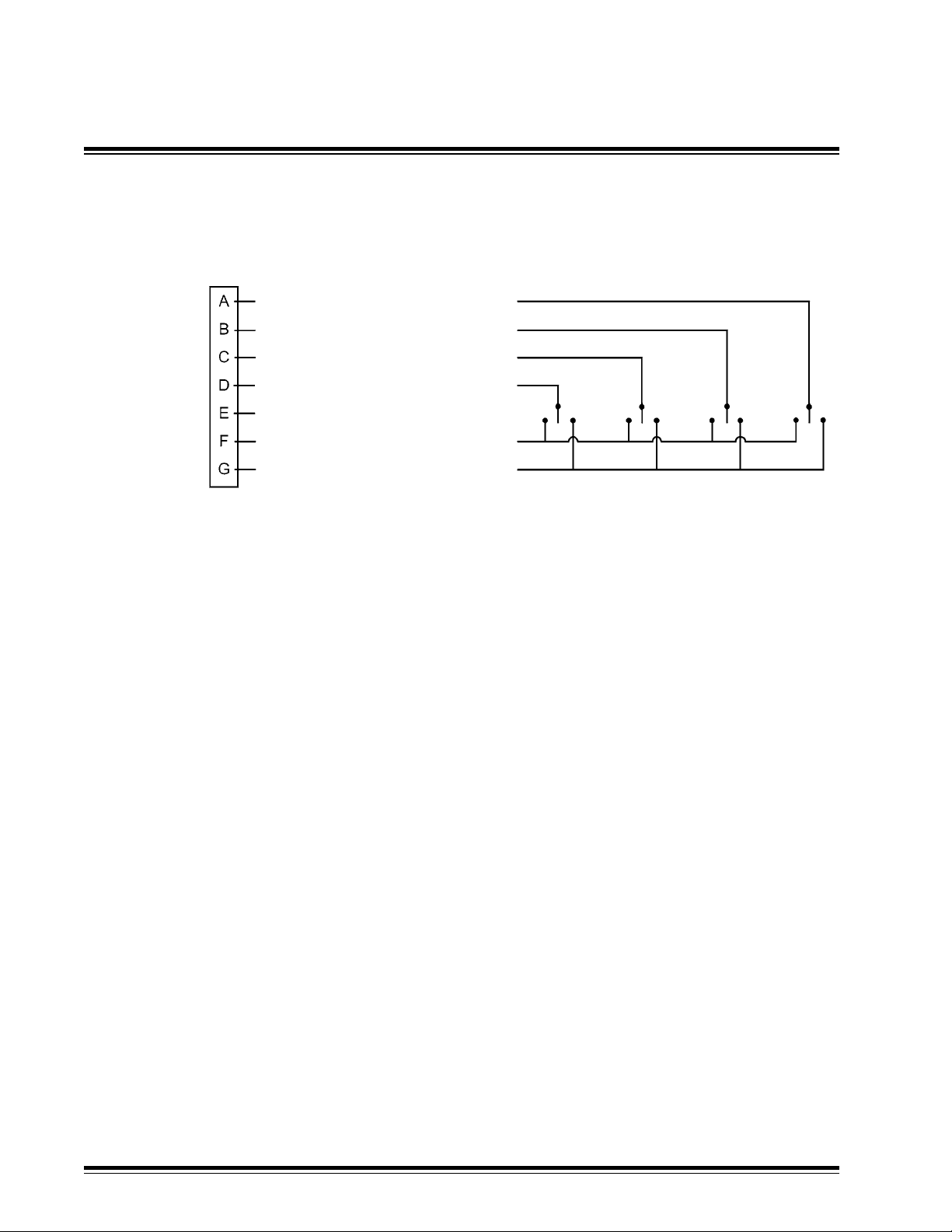
4.6 Miscellaneous Cable Installation Notes
Toggle Remote Switch Wiring
LH Auto / Manual
LH Raise/ Lower
RH Auto / Manual
RH Raise / Lower
N/C
Rem. Sw. Power
Rem. Sw. Ground
Use momentary toggle switches.
Left Hand Auto / Manual
Connecting Pin A to Ground toggles LH control to Manual
Connecting Pin A to Power toggles LH control to Auto
Right Hand Auto / Manual
Connecting Pin C to Ground toggles RH control to Manual
Connecting Pin C to Power toggles RH control to Auto
LH Raise / Lower
Connecting Pin B to Ground creates LH valve Lower signal
Connecting Pin B to Power creates LH valve Raise signal
Orange*
Green
Blue
White
Red
Black
RH Raise / Lower
Connecting Pin D to Ground creates RH valve to Lower signal
Connecting Pin D to Power creates RH valve Raise signal
Single LH or RH Toggle switches should be wired as LH switches.
LH or RH assignment will be selected with "Remote Cong" function in the
System Setup menu.
*A cable assembly with the connector wired per above schematic but with no
toggle switches and housings attachd is available as P/NATI-010998-XX.
MCB3 Installation ManualPage 22
Page 25
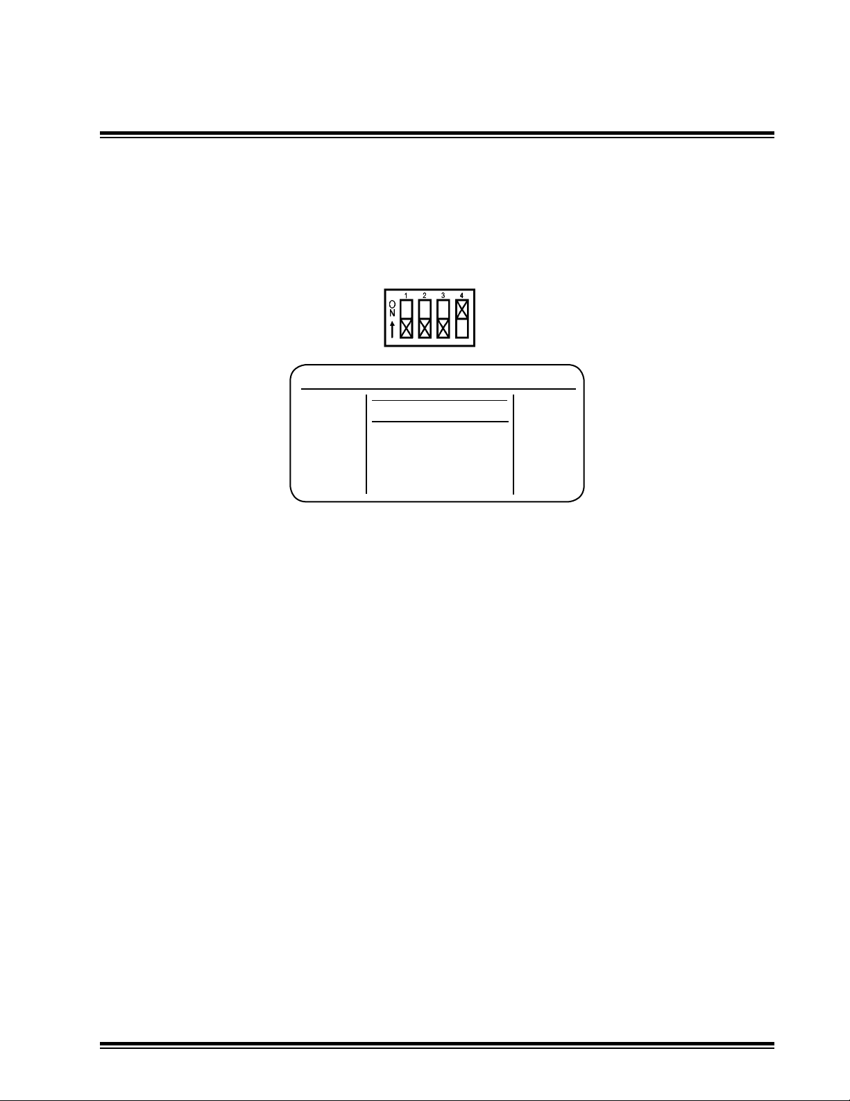
Technical Setup
5.1
The Technical Setup Menu is used to congure the machine during initial installation.
It is recommended that the operator not have access to this menu.
To access the Technical Setup Menu, remove the access panel thumb screws and plate.
Move BAT 4 on the DIP switch into the ON position as shown.
The following screen appears:
Technical Setup Menu
Technical Setup Menu
< Exit >
System Setup
Valve Setup
Custom Setup
The Technical Setup Menu consists of six sections:
System Setup
Valve Setup
Custom Setup
Troubleshoot
Store / Recall
Data Transfer
Each section has submenus. Menu availability and selection options will vary depending on
valve type selected, machine architecture, and model of sensors attached.
The menus are organized so that moving from the top to the bottom through the menus and
submenus provides the best order for system setup.
The menu is navigated by using the left or right multi-switch. Toggle the multi-switch down
to highlight the item below the current selection and to scroll down. Toggle the multi-switch
up to highlight the selection above the current selection and to scroll up. Press in the multiswitch to enter the highlighted selection.
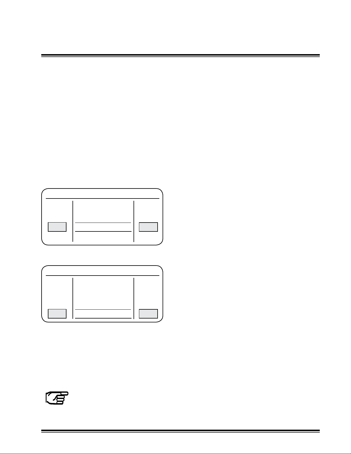
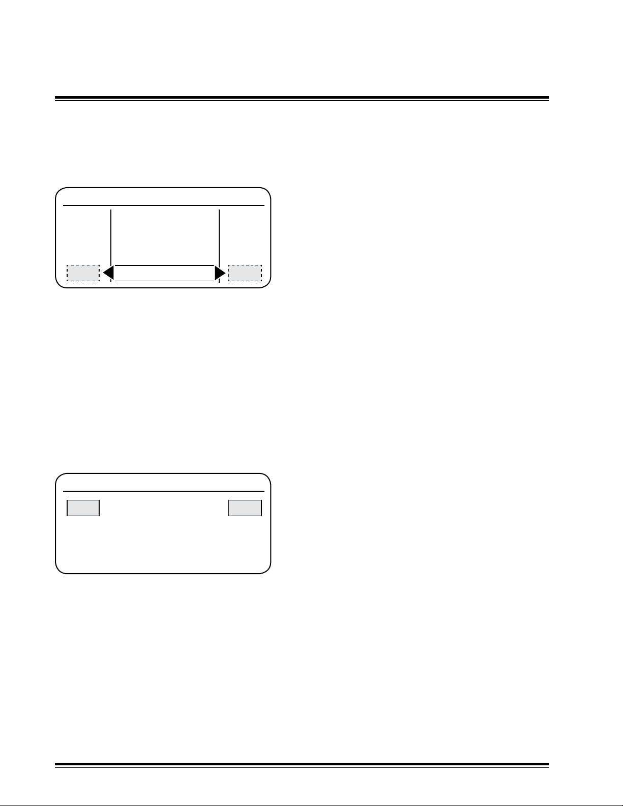
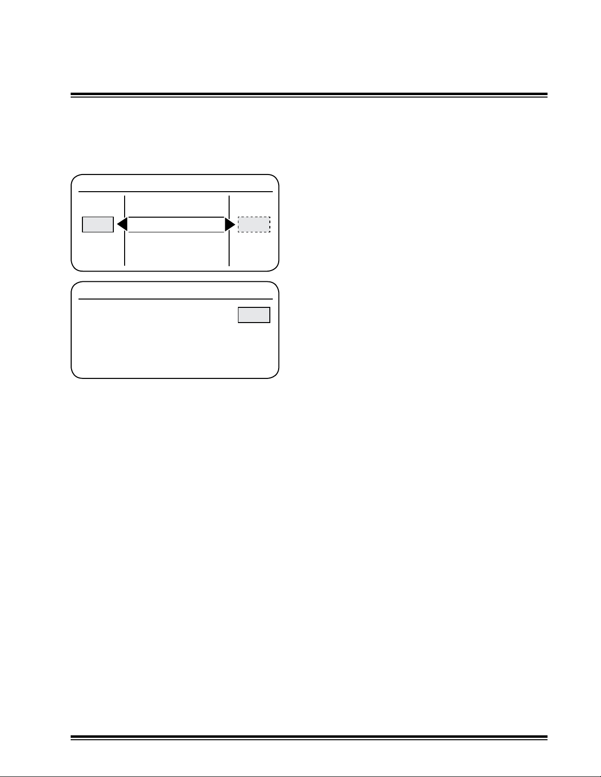
Values or options are selected by rotating the multi-switch for the corresponding left or right
side. An arrow and dotted box indicate the function must be entered to change values.
For numeric values, clockwise rotation increases the value; counterclockwise rotation
decreases the value.
Each section has an Exit function on the top and bottom level. To exit, scroll to the top or
bottom of the menu to highlight <Exit> and press in the multi-switch.
Conguring the System Setup and Valve Setup are generally required for all systems.
Modifying the Custom Setup is generally not required for most systems.
MCB3 Installation Manual Page 23
Page 26

Technical Setup
5.2
System Setup Menu
<Exit>
Language Select Language
Mach Arch Select Machine Architecture
X-Couple Enable Cross Coupling Enable
X-Couple Setup Cross Coupling Compensation Setup
Slope Slope Enable
Ctl%Dsp DB Sets Control Deadband as a Percentage of Display Deadband
Remote Cong Remote Switch Conguration
Remote A/M Remote Switch Auto / Manual Enable
Remote R/L Remote Switch Raise / Lower Enable
Remote Offset Remote Switch Elevation Offset Enable
Remote Match Remote Switch Grade Match Enable
<Exit>
Valve Setup Menu
<Exit>
Aux Vlv Drives Auxiliary Valve Driver Setup
Technical Setup Menu List and Brief Description
PT Valve Selected
PT Period ms Sets update rate for PT Valves
PC Valve Selected
Spool Prole Exponential or Linear Valve Spool
Pk % Dither Dither Amplitude for PC valves only
Dither Hz Dither Frequency for PC valves
PC or PV Valve Selected
Spool Prole Exponential or Linear Valve Spool
All Valves
Max % On Limits amount of power sent to valves
Raise Min Raise Valve Minimum Correction Calibration
Lower Min Lower Valve Minimum Correction Calibration
R/L Balance Dynamic Raise / Lower Balance
RH/LH Balance Balance of Right hand / Left hand Blade Speeds
Valve Speed Nominal Gain for Valves after applying Balance
Slope%Elev Spd Slope speed as a percentage of elevation speed
<Exit>
MCB3 Installation ManualPage 24
Page 27

Technical Setup
5.2
Custom Setup Menu
<Exit>
Out of Beam Alarm Enable out of laser beam audible signal
Up/Down Switch Selects Implement or Mast to Raise / Lower
Display Avg Selects display performance options
Receiver LEDs Receiver LED's On or Off
2 Strike Avg Enables 2 strike laser averaging
R/L Override Enables Raise / Lower switch to override in Auto control
R/L Ramp Enables Raise / Lower switch to ramp up to full speed
Slope Axis Slope Sensor X or Y Axis Select
Receiver Facing Receiver Facing Orientation
<Exit>
Troubleshoot Menu
<Exit>
Machine Voltage Displays Machine Voltage
Fault Log Records History of Fault Occurrences
Clear Fault Log Clears History of Faults
LCD/LED Test Shows Functional LCD/LED's
Key/Switch Test Shows Functional switches
Power Cycles Displays Number of Power Cycles
On Time hrs Displays On Time in Hours
Auto Time hrs Displays Automatic Time in Hours
S/W Version Displays Software Version
S/W Checksum Displays Software Checksum
BL Checksum Displays Bootloader Checksum
<Exit>
Technical Setup Menu List and Brief Description
MCB3 Installation Manual Page 25
Page 28

Technical Setup
5.3
Customer: Location: Date:
Control Box Model: S/N: Machine Information: Valve Type / ID:
LeftSide USER SETUP RightSide
Installation Log
On-grade Deadband
Valve Speed
Store / Recall
Lock / Unlock
SYSTEM SETUP
Machine Architecture
Cross Couple Enable
Cross Coupling Setup
Slope
Control % Display Deadband
Remote Conguration
Remote Auto / Manual
Remote Raise / lower
Remote Elev. Offset
Remote Grade Match
VALVE SETUP
Auxiliary Valve Drivers
Spool Prole
PT Period ms
Pk % Dither
Dither Hz
Max % On
Raise Minimum
Lower Minimum
R/L Balance
RH/LH Balance
Slope % Elev Speed
CUSTOM SETUP
Display Averaging
2-Strike Averaging
R/L Override
R/L Ramp
Receiver Facing
TROUBLESHOOT
Machine Voltage
Fault Log
Power Cycles
On Time hrs
Auto Time hrs
S/W Version
S/W Checksum
BL Checksum
MCB3 Installation ManualPage 26
Page 29

Technical Setup - System
5.4
Highlight System Setup from the Technical Setup Menu and press in the multi-switch.
Toggle the multi-switch up and down to navigate through the System Setup Menu.
Language - Select Language
System Setup Menu
< Exit >
Language
Machine Arch
X-Couple Enable
Mach Arch - Machine Architecture
Selections are Off, Lift, or Tilt for right side and Lift or Off for left side.
Lift & Tilt is used for a typical dozer conguration. Select Lift on left side for elevation
side receiver; Tilt for the right side.
System Setup Menu
Turn the right side multi-switch to select
language used in operating modes.
ENG - English
ENG
GER - German
FRE - French
ITA - Italian
SPA - Spanish
Technical menus remain in English
Lift & Lift is for independently controlled elevation sides, such as a motorgrader.
For single side operation, select Lift for one side and Off on the other side.
Refer to § 3.1 for additional machine architecture information.
X-Couple Enable - Cross Coupling Enable
System Setup Menu
X-Couple Enable
On
X-Couple Setup
Slope
Ctl%Dsp DB
Cross coupling selection is On or Off. When On,
it communicates corrections from one side to
the other that stabilizes the blade's movement.
If On is selected, the Cross Couple Setup must
be completed.
When On, cross coupling is only applied when
both laser receivers are in the laser beam.
MCB3 Installation Manual Page 27
Page 30

Technical Setup - System
5.4
X-Couple Setup - Cross Coupling Setup
System Setup Menu
System Setup Menu
X-Couple Enable
X-Couple Setup
Slope
Ctl%Dsp DB
X- Couple Setup
X
0.0
^
3.250
X
Ft
<Push> to Return
Setup enables entry of geometry for cross
coupling calculations.
Geometry will be determined by machine
architecture selection.
For measurement accuracy, ±.006 m, ±0.25
in., ±0.02 ft is sufficient. Ensure the units of
measure are correct.
Lift and Tilt: Measure the horizontal distance
between the left sensor and the center pivot
point. Scroll the left multi-switch to enter the
measurement.
Measure the horizontal distance between the
right sensor and the center pivot point. Scroll
the right multi-switch to enter the measurement.
On a traditional dozer conguration, the left
receiver will control the lift and will be mounted
over the pivot point on the blade. If so, the distance entered for the left side will be "0".
Push in the multi-switch to exit the setup screen.
X- Couple Setup
X
3.250
^
2.250
Ft
^
3.250
X
<Push> to Return
Highlight the right number and scroll the right multi-switch to enter the measurement.
Measure the horizontal distance between the right side pivot point and the left side pivot
point. Toggle either multi-switch sideways to highlight the center number. Use the same
side switch to enter the measured value.
Push in the multi-switch to exit the setup screen.
Lift and Lift: Use the centered or operating
blade side shift position prior to measurement.
Measure the horizontal distance between the
left sensor and the left side pivot point. Highlight
the left number and scroll the left multi-switch to
enter the measurement.
Measure the horizontal distance between the
right sensor and the right side pivot point.
MCB3 Installation ManualPage 28
Page 31

Technical Setup - System
5.4
Slope - Slope Enable
System Setup Menu
Slope
Ctl%Dsp DB
System Setup Menu
Slope selection is On or Off. When On, the
slope sensors in the receivers, if equipped, are
operational. Slope menu options are available.
On
When Off, the slope sensors are not operational
and slope menu options are not available.
Remote Config
Remote A/M
the receiver is properly oriented - the LED display is parallel to the blade.
Ctl%Dsp DB - Control Deadband as a Percentage of Display Deadband
The display deadband is set from the User Setup menu. The default setting is 100%.
Consequently the display deadband and the control deadband are initially the same.
To decrease the control deadband value, decrease the percentage value. For
example, if the display deadband is 0.50 inches and the Ctl%Dsp DB is set to 50%,
the control deadband would be 0.25 in.
Adjust each side of the system. Display is from 0 to 100 in increments of 1%.
Rotate the right multi-switch to change the selection.
When On - Calibrate the slope sensor. Ensure
NOTE: Smaller control deadband values increase valve movement sensitivity. This
may cause unstable system performance. System performance should be checked
after adjusting. See § 5.6.
Remote Cong - Remote Switch Conguration
The remote switch conguration selects the type of remote switch (Multi-switch or
Toggle), how many switches are used, and which side the switch is mounted.
Multi-switches are not the same as Toggle switches. See cable diagrams for part numbers.
Remote switches are installed with the switch facing inward and the cable routed
downward. Once congured, this installation allows thumb activation for forward
movement to Auto and back movement to Manual.
MULT - Multi-switch. All options for the multi-switch are available.
TOGL - Toggle switch. Auto/Manual and Raise/Lower switch options only.
For Dual Multi-switch, set both sides to MULT, and turn on or off the desired remote
functions for each side in the next four menu items.
For Single remote switches, set the side the switch is mounted on to MULT or TOGL,
and turn the other side to NONE. The single remote switch will activate both left
hand and right hand remote functions. Turn Off or On the desired remote functions in
the next four menu items. The Raise/Lower function for the Tilt side is not available.
Single remote switches are wired as left hand remotes and may be congured to
operate the left hand, right hand, or both sides.
MCB3 Installation Manual Page 29
Page 32

Technical Setup - System
System Setup Menu5.4
Remote A/M - Remote Switch Auto / Manual Enable
Selections are On and Off. On enables switching between Automatic and Manual
with the remote switch.
Off disables switching between Automatic and Manual.
Remote R/L - Remote Switch Raise / Lower Enable
System Setup Menu
On
Remote R/L
Remote Offset
On
Selections are On and Off.
On enables the Raise and Lower command with
the remote switch.
Off disables the Raise and Lower command.
Remote Match
< Exit >
Remote Offset - Remote Switch Elevation Offset Enable
Selections are On and Off.
On enables an elevation offset to be set at the remote switch by rotating the multiswitch. If slope is applicable, a slope change can be made at the switch.
Off disables the offset command.
Remote Match - Remote Switch Grade Match Enable
Selections are On and Off.
On enables an off-center laser strike to be set to on-grade with the remote switch by
pressing in the multi-switch and holding for two seconds.
The on-grade position can be reset to the center of the receiver by pressing in the
multi-switch and holding for ve seconds.
Off disables the match command.
Highlight Exit and press in the multi-switch to return to the Technical Setup Menu.
MCB3 Installation ManualPage 30
Page 33

Technical Setup - Valve
5.5
Technical Setup Menu
< Exit >
System Setup
Valve Setup
Custom Setup
Toggle the multi-switch to highlight Valve Setup. Rotate the left and right multi-switch to
select PV, PC, or PT.
Each valve type has its individual characteristics.
The PT valve, sometimes referred to as on/off or "bang-bang" valve is not a true proportional
valve. It can only be turned on or off. The proportionality is achieved by rapidly turning the
valve on and off over time at varying duty rates.
The PC and PV valves are proportional spool valves and can take full advantage of the
receivers proportional electronics.
Valve Setup Menu
The type of valve used is selected from the
initial Technical Setup Menu.
Selections are PC, PT, or PV.
PC - Proportional Current
PVPV
PT - Proportional Time
PV - Proportional Voltage
A common PV valve is the Danfoss PVG32, which is a pilot operated proportional valve.
Once the valve type is selected, press in the multi-switch to enter additional Valve Setup
options.
Menu items will appear depending on the type of valve selected. If both sides have the
same valve, menus specic to that valve will appear. If different valves are selected for
each side, all menu items will appear.
MCB3 Installation Manual Page 31
Page 34

Technical Setup - Valve
5.5
Aux Vlv Drives - Auxiliary Valve Driver Setup
Valve Setup Menu
< Exit >
Aux Vlv Drives
SP (Switched Power)
LS (Load Sense)
LSA (Load Sense A)
SP supplies Machine Voltage anytime the control box is on.
NOTE: SP is required for PV valves.
LS supplies Machine Voltage when either side of the control box is in AUTO mode
and receiving laser strikes, or when raising or lowering.
LSA supplies Machine Voltage when either side of the control box is in AUTO mode
or when raising or lowering.
If auxiliary valve drivers are not used, turn to OFF to avoid unused live wires.
Spool Profile
(Next menu items change
per valve type selected)
Valve Setup Menu
Selections enable setting of valve drivers for
specic applications and types of valves.
Selections are:
SPSP
OFF
PT Valve Selected
PT Period ms- Selects the update period for PT valves.
Adaptive optimizes the signal according to the
laser RPM.
Other values can be set from 100 to 250 in
increments of 10 ms.
ADPT
Valve Setup Menu
< Exit >
Spool Profile
PT Period ms
ADPT
Max % On
PC or PV Valve Selected
Spool Prole
Valve Setup Menu
Aux Vlv Drives
Spool Profile
(Next menu items change
per valve type selected)
EXPEXP
Spool prole selections are exponential (EXP)
and linear (LIN).
Choose the same prole as the installed valve
spool.
PC valves usually have exponential (EXP)
spool proles.
MCB3 Installation ManualPage 32
Page 35
Technical Setup - Valve
5.5
Dither is a signal which is constantly sent to the PC valve that causes the spool to vibrate
and stay lubricated, reducing hysteresis and stiction.
Choose a setting closest to the manufacturers recommendations or use the Valve
Identication and Setting Recommendation chart in Appendix A.
If cylinder lines or cylinder are vibrating from dither, select a higher frequency and/or lower
the % amplitude.
If the valve is sticking or sluggish, select a lower dither frequency and/or a higher % amplitude.
Pk Dither - Dither Current Amplitude for PC valves only
Valve Setup Menu
Aux Vlv Drives
Spool Profile
Pk Dither
Dither Hz
Valve Setup Menu
PC Valve Selected
Select the dither amplitude according
to the Valve Identication and Setting
Recommendation chart in Appendix A. Select by
rotating the right or left side multi-switch. Values
2020
are between 0 and 25 in increments of 1%.
Dither Hz - Dither Frequency for PC valves
Valve Setup Menu
Aux Vlv Drives
Spool Profile
Pk Dither
Dither Hz
Once the proper valve is selected, perform a system communication check. Turn the box on
to conrm power. Check that the receiver is communicating properly. Check the raise/lower
and auto/manual switches. Check the remote switch functions if installed.
Check for proper hydraulic system operation. Ensure there are no leaks, excessive engine
load or pressure relief valves continually opening. Check that all circuits function properly.
NOTE: Before proceeding, warm up the hydraulic system to operating temperature.
Run the machine at operating RPM for approximately 15 minutes while cycling
the blade lift cylinder.
100100
Select the dither frequency according
to the Valve Identication and Setting
Recommendation chart in Appendix A. Rotate
the right side multi-switch to select.
Values are 40 / 42.1 / 44.4 / 47.1 / 50 / 53.3 /
57.1 / 61.5 / 66.7 / 72.7 / 80 / 88.9 / 100 / 114.3
/ 133.3 / 160 / 200 / 266.7 / 400.
MCB3 Installation Manual Page 33
Page 36
Technical Setup - Valve
5.5
Max % On - Limits power sent to valves
Valve Setup Menu
Spool Profile
Pk Dither
Dither Hz
Max % On
For PC or PT Valves:
The maximum current supplied to the solenoid is equal to machine voltage divided
by coil resistance.
Reference Appendix A for PC valve solenoid descriptions for common valves.
Example: If a solenoid with a maximum rated current of 2.5 Amps (I) and resistance
of 3 Ohms (Ω) is installed on a 12 Volt (V) machine, the maximum supplied current
will be I = V/R ; 12V/3Ω = 4A. Adjust the Max % On to 2.5A/4.0A = 63% to stay
within the solenoids maximum current rating.
Valve Setup Menu
All Valves
Max % On adjusts Pulse Width Modulation
(PWM) percentage to create a less than 100%
proportional valve signal.
If the valve's maximum signal rating is less
than the maximum supplied signal, lower the
100100
maximum supplied signal to within the valve's
maximum rated signal.
Max % On Test
Max % On Test
100 100
Max % On
<UP/DOWN> to Test
<Push> to Return
Push in the Multi-switch to change and test the
system. A screen similar to the one depicted
appears.
Rotate the left and right multi-switch to adjust
the percentage.
Toggle the multi-switch up and down and
ensure the valve raises and lowers the
implement.
MCB3 Installation ManualPage 34
Page 37

Technical Setup - Valve
5.5 Valve Setup Menu
Set Valve Minimum Correction
The Valve Minimum Correction (VMC) is set to provide output ow as soon as a correction
signal is received.
Spool Overlap - Minimum distance
to move valve for ow to begin.
The edges of the valve spool have some degree of overlap with the corresponding edges of
the valve body ports. This is required to prevent ow across the spool when it is in a neutral
position. This spool overlap means that there will be a dened movement of the spool in the
bore before ow begins to take place. This characteristic is sometimes referred to as valve
“deadband”. In this text, adjusting the control box to account for this deadband and create a
minimum blade velocity will be referred to as the Valve Minimum Correction (VMC) to avoid
any confusion with laser system deadband or accuracy.
The minimum correction is set independently for both the raise and lower.
Set the machine throttle to normal operating RPM and place the blade approximately 1 foot
(0.3 m) above the ground. No laser is required.
Select Raise Min from the Valve Setup Menu.
Valve Setup Menu
Raise Min
2020
Lower Min
R/L Balance
RH/LH Balance
MCB3 Installation Manual Page 35
Page 38

Technical Setup - Valve
5.5 Valve Setup Menu
Raise Min - Raise VMC Calibration
Raise Min Test
20 20
Raise Min
<UP> to Test
<Push> to Return
multi-switch. Repeat the switch raise until the blade speed is approximately 0.5 inches
(13 mm) per second.
If the blade speed is too fast, decrease the numeric value until a speed of 0.5 inches
(13 mm) per second is attained.
If the cylinders bottom out, the lower switch can be used to reposition the blade.
Repeat the process for the right hand valve.
Push in the multi-switch to return to the valve setup menu.
Lower Min - Raise VMC Calibration
Lower Min Test
15
Lower Min
15
<DOWN> to Test
<Push> to Return
Push in the multi-switch with the Raise Min
selected from the Valve Setup Menu. A screen
similar to the one depicted appears.
Toggle the left hand multi-switch to the raise position
and hold.
If there is no movement, release the switch and
increase the numeric value by one by rotating the
Select Lower Min from the valve setup menu.
A screen similar to the one depicted appears.
Toggle the left hand multi-switch to the lower
position and hold.
If there is no movement, release the switch and
increase the numeric value by one by rotating
the multi-switch. Repeat the switch lower until the
blade speed is approximately 0.5 inches (13 mm)
per second.
If the blade speed is too fast, decrease the numeric value until a speed of 0.5 inches
(13 mm) per second is attained.
If the cylinders bottom out, the raise switch can be used to reposition the blade.
Repeat the process for the right hand valve.
Push in the multi-switch to return to the valve setup menu.
MCB3 Installation ManualPage 36
Page 39

Technical Setup - Valve
5.5
R/L Balance - Dynamic Raise / Lower Balance
The valve raise / lower balance set-up allows adjustment to compensate for different raise and
lower blade velocities due to cylinder imbalance or for different hydraulic system responses
to different loads.
Most mobile equipment uses double-acting hydraulic cylinders. Double-acting cylinders are also
called differential cylinders because the effective area, and therefore the volume, of each end
of the cylinder is different. The rod end of the cylinder has less area and volume than the cap
end by the nature of the rod being present. This differential area and volume causes a different
force and velocity during extension and retraction - or raising and lowering for a lift cylinder.
Cap end of cylinder has greater volume and area than rod end.
Set the machine throttle to normal operating RPM and place the blade approximately 1 foot
(0.3 m) above the ground. No laser is required.
Valve Setup Menu
Raise Lower Balance Test
20
R/L Balance
-10
<UP/DOWN> to Test
<Push> to Return
Right side - Tilt (for Lift & Tilt): Toggle the raise / lower switch to raise and hold. The
blade will oscillate about the tilt pivot point. Observe the blade drifting.
If the right side drifts downward, increase the right side numeric value. If the right side
drifts upward, decrease the right side numeric value. Test the movement again and
adjust until the blade is balanced about the pivot point.
Right side - Lift and Lift: Same procedure as the left side using the right side multiswitch.
Select R/L Balance from the Valve Setup Menu.
A screen similar to the one depicted appears.
Left side - Lift: Toggle the raise / lower switch to
raise and hold. The blade will oscillate up and
down. Observe the blade drifting up or down
during oscillation.
If the blade is drifting upward, lower the left hand
numeric value. If the blade is drifting downward,
raise the left hand numeric value. Test the
movement again and adjust until the blade is
balanced.
MCB3 Installation Manual Page 37
Page 40

Technical Setup - Valve
5.5
RH/LH Balance - Balance Right Hand / Left Hand Blade Speeds
RH/LH Balance Test
RH/LH Balance
Valve Setup Menu
Ideally, the right hand and left hand blade velocities
should be the same. The Right Hand / Left Hand
0
Balance Test and adjustment allow adjustment
to compensate for different velocities of the right
and left hand sides of the blade.
<UP/DOWN> to Test
<Push> to Return
valves or the mechanics of the machine.
For Lift & Tilt machines with the pivot point in the middle of the blade, adjust RH/LH
balance until oscillation amplitude of the left hand end of the blade during the test is
minimized.
For Lift & Lift machines: Adjust RH/LH balance
until oscillation amplitude of the blade during the
test is nearly equal for right hand and left hand
sides.
The RH/LH balance may be limited by unmatched
For Lift & Tilt machines with pivot points not in the center of the blade, adjust the RH/LH
balance so that the lift and tilt velocities are about the same when in operating modes.
The Test is not required. Measure the tilt blade velocity at the end of the blade farthest
from the pivot point.
Clockwise adjustment of the right multi-switch (larger value) will increase the speed
of the right side.
Counterclockwise adjustment of the right multi-switch (smaller value) will decrease the
speed of the right side.
MCB3 Installation ManualPage 38
Page 41
Technical Setup - Valve
5.5
Valve Speed - Sets System Speed
Valve Setup Menu
RH/LH Balance
Valve Speed
50
Slope % Elev Spd
<Exit>
Valve Speed Test
Valve Speed
50
<AUTO> to Test
<Push> to Return
Valve Setup Menu
Select Valve Speed from the Valve Setup Menu
and enter.
Rotate the right multi-switch to change the valve
speed. Values are selectable from 0 to 100.
The valve speed is applied to both valves.
The factory default setting is 50.
Presetting Valve Speed - Blade in Air Method:
1. Set up the rotating laser at a typical working range. If a selectable rotation speed is available,
set it to 600 RPM or faster.
2. Mount the receiver in its normal operating position to receive the laser.
3. Select an On-grade deadband of approximately 1/2 of the jobsite tolerance. If working at
ranges that exceed 500 feet (150 m), this may be increased to compensate for the rotating
laser's beam "bounce".
4. Set the machines throttle to normal operating RPM. Ensure the machine is on at ground.
5. Place the blade approximately 1 foot (0.3 m) above the ground.
6. Select Manual control. Raise the blade to position the receiver at the lower edge of its
vertical reception range, but still receiving the beam. Select Automatic control.
7. The blade and receiver will move towards on-grade. Note any overshooting of On-grade.
Repeat procedure for raise correction. Once again, note any overshooting of On-grade. Adjust
the Valve Speed until there is none or one small overshoot for a full receiver length correction
in either direction of both sensors.
Increasing Valve Speed corresponds to a faster, but less stable correction.
Decreasing Valve Speed corresponds to a slower, but more stable correction.
If one side seems more reactive than the other side, the RH/LH Balance may be used to
correct this.
MCB3 Installation Manual Page 39
Page 42

Technical Setup - Valve
5.5 Valve Setup Menu
Slp%Elev Spd - Slope Speed as a Percentage of Elevation Speed
The slope sensors cannot operate as fast
Slp%Elev Spd Test
Slp%Elev Spd
10
as the elevation sensors of the system.
This adjustment sets the speed of the slope
correction as a percentage of the elevation
correction speed.
<Push> to Return
To preset the Slope Speeds, select a slope operating mode from the main menu.
Presetting Slope%Elev Valve Speed - Blade in Air Method:
1. Mount the receiver in its normal operating position to receive the laser.
2. Select an On-grade deadband typically between 0.3% and 1.0% (0.2º and 0.6º) depending
on the jobsite tolerance. Refer to Appendix D for more details.
3. Set the machines throttle to normal operating RPM. Ensure the machine is on at
ground.
4. Place the blade approximately 1 foot (0.3 m) above the ground.
5. Select Manual control. Tilt the blade to create a coarse (full arrow) lower correction. Select
Automatic control.
7. The blade and receiver will move towards on-grade. Note any overshooting of On-grade.
Repeat procedure for raise correction. Once again, note any overshooting of On-grade. Adjust
the Valve Slope%Elev until there is none or one small overshoot for a coarse correction in
either direction of both sensors.
This lower speed is only applied to the slope
sensor driven side.
Increasing Slope%Elev Speed corresponds to a faster, but less stable correction.
Decreasing Slope%Elev Speed corresponds to a slower, but more stable correction.
NOTE: After the Valve Setup is complete, it is recommended to name and save
the settings for future reference. Refer to § 5.8.
MCB3 Installation ManualPage 40
Page 43

Technical Setup - Valve
5.6
Set up the rotating laser at a typical working range. Select the RPM of the laser to 600 RPM
or faster if available.
Mount the MCR receivers to the mast of the machine in a position to receive the
beam.
Select an On-grade deadband less than the jobsite tolerance. Typically 1/2 the tolerance is
the value used as a starting point.
Select the desired operating mode.
Fine tune the Valve Speed while working in typical material and operating conditions.
If the system is over correcting or too jumpy, decrease the valve speed setting.
If the system is not correcting fast enough or is sluggish, increase the valve speed setting.
If one side seems more reactive than the other side, the RH/LH Balance may be used to
correct this.
Environmental factors and laser set up can also affect system performance. Follow the set up
procedures for your laser. Ensure proper tripods are used for stable laser operation.
Changing the laser RPM, laser strike averaging, deadband, spool prole, valve speed, valve
balancing, or valve minimum corrections can affect system performance. System operation
should be rechecked after changing any of these parameters.
Check System Performance
MCB3 Installation Manual Page 41
Page 44

Technical Setup - Custom
5.7
Out of Beam Alarm - Enable out of laser beam audible signal
Custom Setup Menu
< Exit >
Out of Beam Alarm
Up/Down Switch
Custom Setup Menu
Select On to enable out of laser beam audible
signal. One double beep is emitted when the
receiver does not receive a laser beam strike for
On
approximately one second.
Select Off to disable out of beam audible signal.
Display Avg
Up/Down Switch - Select Implement (Impl) or Mast (Mast) to Raise / Lower
Select Implement to raise / lower implement.
Select Mast to raise / lower mast (for use with electric mast; currently not available.)
(Dependingonsoftwarereleasedate,thisfunctionmaynotbeavailable.)
Display Avg - Selects display performance options (Does not affect control)
Selections include None - No averaging, each strike received is displayed.
Adaptive (Adpt) - Adapts to laser RPM (recommended for
most applications).
Fast - Minor averaging function applied to display
Stable (Stbl) - More averaging function applied to display.
Receiver LEDs - Turns Receiver LED's On or Off
Select On or Off. User preference for the receiver LED's.
2 Strike Avg - Enables 2 strike laser averaging (Affects control)
Select On or Off.
On is used in environments that may cause unstable behavior such as very windy
conditions and working long distances from the laser.
The 2 strike averaging will slow system response. Adjustments to the valve speed or
on-grade deadband may be required to maintain stability.
R/L Override - Enables Raise / Lower switch to override in Auto control
Select On or Off.
Custom Setup Menu
2 Strike Avg
R/L Override
When On, the manual raise and lower switch
will override the automatic control. When
released, automatic control will resume.
R/L Ramp
Receiver Facing
MCB3 Installation ManualPage 42
Page 45

Technical Setup - Custom
5.7
Custom Setup Menu
R/L Ramp
Slope Axis
Receiver Facing
<Exit>
Slope Axis - Selects X or Y Axis for receivers equipped with dual slope sensors.
Y is the default, tilt axis - "side to side" with respect to the receiver's grade display.
X is the plumb axis and would be set for a special application when the receiver would
operate rotated 90 degrees about the vertical axis from its normal orientation - "front to
back" with respect to the receiver's grade display.
(Dependingonsoftwarereleasedate,thisfunctionmaynotbeavailable)
Receiver Facing
Custom Setup Menu
R/L Ramp - Enables Raise / Lower switch to
ramp up to full speed
Select On or Off.
On allows a progressive increase for the
valve to get to the 100% open state in the rst
second.
Selection allows for consistent slope directions on the controls for either mounting
option if internal slope sensors are used. Selects orientation of receiver. For
receivers mounted on the front of the machine in front of the operator with LED's
facing back toward the operator, select "Back". For receivers in the back of the
machine behind the operator with LED's facing toward the front, select "Frnt" for
front.
MCB3 Installation Manual Page 43
Page 46
Technical Setup - Troubleshoot
5.8
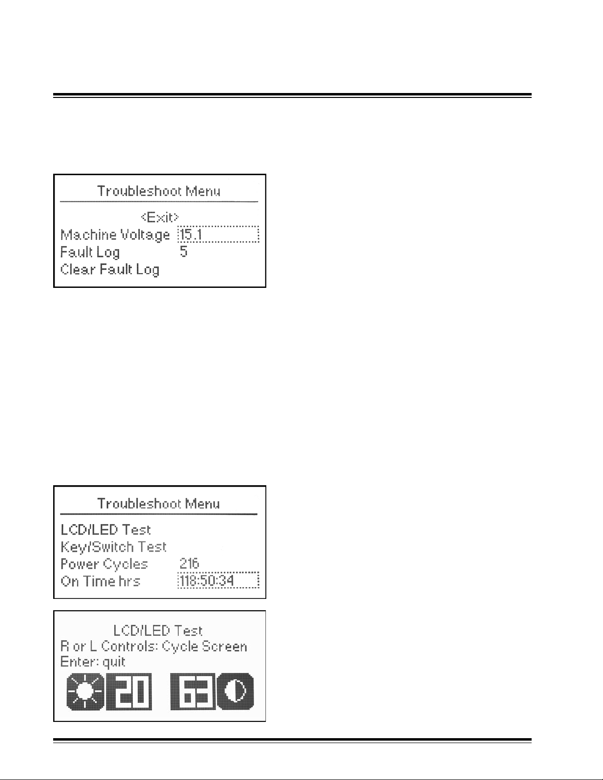
Machine Voltage - Displays machine voltage.
Fault Log - Records history of fault occurrences.
Records relevant information regarding a fault including time of fault and fault code.
Press in the multi-switch to enter the log. Rotate the multi-switch to view fault entries.
Press the power switch up while viewing fault entries to display the fault description.
Refer to Appendix B for specic fault code information.
Troubleshoot Menu
Clear Fault Log - Clears all history in the fault log.
Press in the multi-switch to clear the fault log.
LCD/LED Test
Tests for LCD brightness, contrast, and light or
dark pixels. Lights LED's in sequence.
Press in the multi-switch to enter the LCD/LED
test.
Rotate the left multi-switch to adjust the
brightness.
Rotate the right multi-switch to adjust the
contrast.
MCB3 Installation ManualPage 44
Page 47
Technical Setup - Troubleshoot
5.8
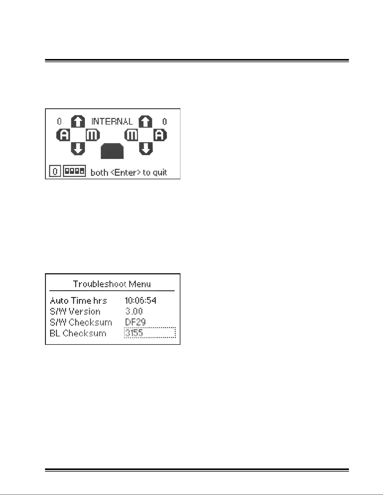
Key/Switch Test - Graphically displays switch activations.
Power Cycles - Counts the number of power cycles.
On Time hrs - Displays the number of hours the system is On.
Format is "hrs : min : sec".
Auto Time hrs - Displays the number of hours the system is in Automatic.
Format is "hrs : min : sec".
Troubleshoot Menu
Press Power Switch up to switch between
tests of Internal switches (Multi-, rotary, and
dip switches), Remote Toggle switches, and
remote Multi-switches.
Press in both multi-switches to quit the test
mode.
S/W Version - Displays Installed Software Version
S/W Checksum - Displays Software Checksum
BL Checksum - Displays Bootloader Checksum
MCB3 Installation Manual Page 45
Page 48

Technical Setup - Store / Recall
5.9
Store / Recall
The control box uses setups that are in "current"
memory to operate.
The control box saves to current memory all setup
values when exiting the Technical Setup Menus.
It also saves to current memory every 30 seconds
while in the operating mode.
The control box has one default memory slot for
Store Recall
storing a factory setup. It also has four memory slots
for saving installer or user customized setups.
The user or installer may copy a setup from current memory to 1 of 4 named memory slots
with the Store function.
The user or installer may copy a stored setup from the 4 named or 1 default memory slot to
the current memory using the Recall function.
The Store / Recall function in the Technical Setup Menu is the same Store / Recall function
in the User Setup.
Store is on the left side. To store a current conguration, rotate the left multi-switch to the
desired number 1 through 4. When selected, press in the multi-switch. A menu will ask if
you would like to store. Select 'Yes' to store. Select 'No' to return to the previous menu.
If Yes is selected, a new name can be entered for the stored setting.
Rotate the multi-switch to scroll and stop on the desired character. Move the multi-switch
to the right to allow selection of the next character. Continue until complete. Up to seven
characters may be used. Once entered, the named setting will appear on the store and
recall side for further use.
Recall is on the right side. To recall a stored conguration, rotate the right multi-switch
to the desired number or name. Press in the right multi-switch. A screen will ask if you
would like to recall. Select 'Yes' to recall and make the stored conguration the current
conguration. Select 'No' to return to the previous menu.
Checksum values are displayed to check copied setups.
5.10
Data Transfer
The Data Transfer function along with the CB Center PC application software allows
presets to be saved from a control box to a PC, and recalled from a PC to a control box via
a serial cable.
Refer to the instructions that come with the CB Center software for further details.
MCB3 Installation ManualPage 46
Page 49

Valve Identication and Setting Recommendation
APPENDIX A
Valve Identication CB52 Setting
Mfgr. Model Number Solenoid Solenoid Description Drive Dither Pk Dither Max %
ID Type Freq. Ampl. On
(Hz.) (%) (%)
Danfoss PVG32 with PVEH elect. Module 157B4016 12VDC, Active Fault, Hrshmn conn. PV N/A N/A N/A
Danfoss PVG32 with PVEH elect. Module 157B4028 24VDC, Active Fault, Hrshmn conn PV N/A N/A N/A
Danfoss PVG32 with PVEH elect. Module 157B4086 12VDC, Passive Fault, Hrshmn conn. PV N/A N/A N/A
Danfoss PVG32 with PVEH elect. Module 157B4088 24VDC, Passive Fault, Hrshmn conn. PV N/A N/A N/A
Danfoss PVG32 with PVEH elect. Module 157B4032 11-32VDC, Active Fault, Hrshmn conn. PV N/A N/A N/A
Danfoss PVG32 with PVEH elect. Module 157B4033 11-32VDC, Passive fault, Hrshmn conn. PV N/A N/A N/A
Danfoss PVG32 with PVEH elect. Module 157B4034 11-32VDC, passive Fault, Amp conn. PV N/A N/A N/A
Danfoss PVG32 with PVEH elect. Module 157B4035 11-32VDC, Active Fault, Amp conn. PV N/A N/A N/A
Vickers/Eaton KDG4-3S….. GP 12VDC, 4.9 Ohms PC 100 20% 100
Vickers/Eaton KDG4-3S….. HA 24VDC, 19.6 Ohms PC 100 20% 100
Vickers/Eaton KDG4-3S….. G 12VDC, 1.8 Ohms PC 100 20% 50
Vickers/Eaton KDG4-3S….. H 24VDC, 7.3 Ohms PC 100 20% 50
Nachi ESD…… 24VDC, 20 Ohms PC 100 20% 100
Parker D1FW…. K 12VDC, 6 Ohms PC 100 20% 100
Parker D1FW…. J 24VDC, 24 Ohms PC 100 20% 100
Parker D3FW…. K 12VDC, 4 Ohms PC 100 20% 100
Rexroth 4 WRAB6….. G12 12VDC, 4.8 Ohms PC 200 20% 100
Rexroth 4 WRAB6….. G24 24VDC, 19.2 Ohms PC 200 20% 100
Bosch 0811-404 …. 12VDC, 3.0 Ohms (2.5 A) PC 200 20% 63
Bosch 0811-404 …. 24VDC, 3.0 Ohms (2.5 A) PC 200 20% 32
Recommendations
Danfoss PVG32 with PVEO elect. module 157B4216 12VDC, Hrshmn conn. PT N/A N/A N/A
Danfoss PVG32 with PVEO elect. module 157B4228 24VDC, Hrshmn conn. PT N/A N/A N/A
Danfoss PVG32 with PVEO elect. module 157B4901 12VDC, Amp conn. PT N/A N/A N/A
Danfoss PVG32 with PVEO elect. module 157B4902 24VDC, Amp conn. PT N/A N/A N/A
Vickers/Eaton DG4V-3….. GH 12VDC, 3.8 Ohms PT N/A N/A N/A
Vickers/Eaton DG4V-3….. HH 24VDC, 15.9 Ohms PT N/A N/A N/A
Nachi SS-G0….. D1 12VDC, 4.8 Ohms PT N/A N/A N/A
Nachi SS-G0….. D2 24VDC, 19.2 Ohms PT N/A N/A N/A
Parker D3W…. K 12VDC, 4 Ohms PT N/A N/A N/A
Parker D3W…. J 24VDC, 16 Ohms PT N/A N/A N/A
Parker BV06….. D012 12VDC, 5 Ohms PT N/A N/A N/A
Parker BV06….. D024 24VDC, 20Ohms PT N/A N/A N/A
Parker D1VW….. K 30 watt 12VDC, 4.3 Ohms PT N/A N/A N/A
Parker D1VW….. J 30 watt 24VDC, 17.3 Ohms PT N/A N/A N/A
Bosch/Rexroth 4WE6….., 4WE10…. G24 24VDC, 19.2 Ohms PT N/A N/A N/A
Bosch/Rexroth 4WE6….., 4WE10…. G12 12VDC, 4.8 Ohms PT N/A N/A N/A
Continental VSD03M….. 42L, 70L 24VDC, 24 Ohms PT N/A N/A N/A
Continental VSD03M….. 44L, 75L 12VDC, 6 Ohms PT N/A N/A N/A
MCB3 Installation Manual Page 47
Page 50

APPENDIX B
Fault Codes
Fault code messages may be cleared by activating either multi-switch
Code Description
10401 LH Raise Driver Overload. Valve Conn. Pin B
If Current Exceeds 5 Amps driver turns off for 250ms. If 3 shut offs in 5.0 sec.,
LH drivers stay off until power is cycled.
10402 LH Lower Driver Overload. Valve Conn. Pin A
If Current Exceeds 5 Amps driver turns off for 250ms. If 3 shut offs in 5.0 sec.,
LH drivers stay off until power is cycled.
10403 RH Raise Driver Overload. Valve Conn. Pin F
If Current Exceeds 5 Amps driver turns off for 250ms. If 3 shut offs in 5.0 sec.,
RH drivers stay off until power is cycled.
10404 RH Lower Driver Overload. Valve Conn. Pin G
If Current Exceeds 5 Amps driver turns off for 250ms. If 3 shut offs in 5.0 sec.,
RH drivers stay off until power is cycled.
10405 LH/AUX Driver Overload. Valve Conn. Pin C
If Current Exceeds 5 Amps driver turns off for 250ms. If 3 shut offs in 5.0 sec.,
driver stays off until power is cycled.
10406 RH/AUX Driver Overload. Valve Conn. Pin D
If Current Exceeds 5 Amps driver turns off for 250ms. If 3 shut offs in 5.0 sec.,
driver stays off until power is cycled.
10407 LH PV Driver Overload. Valve Conn Pin E
If Current Exceeds 6 mA driver turns off for 250ms. If 3 shut offs in 5.0 sec.,
driver stays off until power is cycled.
10408 RH PV Driver Overload. Valve Conn Pin H
If Current Exceeds 6 mA driver turns off for 250ms. If 3 shut offs in 5.0 sec.,
driver stays off until power is cycled.
10409 LH Receiver Overload. Receiver Conn Pin A
If Current Exceeds 6.5A driver turns off .
10410 RH Receiver Overload. Receiver Conn Pin G
If Current Exceeds 6.5A driver turns off .
10510 LH PV Fault, Danfoss Valve; PV signal exceeds 15-85% of Mach Volt,
LVDT wires Broken, Spool position exceeds command.
Fault will clear when fault removed and power cycled.
10511 RH PV Fault, Danfoss Valve; PV signal exceeds 15-85% of Mach Volt,
LVDT wires Broken, Spool position exceeds command.
Fault will clear when fault removed and power cycled.
10604 Machine Volts High, Machine Voltage greater than 31.5 volts.
10605 Machine Volts Low, Machine Voltage less than 9.5 volts.
1505 Momentary lapse of communication with the laser receiver(s). Usually occurs due to low
power during engine cranking. Cycling Power re-establishes communication.
10501 Default Values Loaded - Occurs when updating software (V1.00 to V2.00) due to
parameter memory location changes.
MCB3 Installation ManualPage 48
Page 51

Hydraulic Valve Guide
PC - Proportional Current Valve:
PC valves are proportional spool valves.
APPENDIX C
Valve Speed = 1%
Lower
Correction
On Grade
Deadband
Raise
Correction
0% 50% 100%Valve Min.
Correction
Valve Speed = 50%
Valve Speed= 100%
Valve Speed= 100%
Valve Speed = 50%
Valve Speed = 1%
PC Valve Signal
(% of Maximum Current)
The maximum current supplied to the valve solenoid is equal to machine voltage divided by
coil resistance.
Pulse Width Modulation (PWM) is used to create the < 100% proportional current signal.
The PC signal energizes 1 coil at a time which slides the valve's spool back and forth
changing the valve's orice size which changes the oil ow rate.
If the valve's maximum current rating is less than the maximum supplied current, (machine
voltage / coil resistance), use the Max % On setting in the Valve Setup Menu § 5.5 to lower
the maximum supplied current to within the valve's maximum rated current. Reference
Appendix A for PC Valve Identication and Setting Recommendations.
Application Note: PC Valves are typically fast, but not always accurate.
Direct operated solenoid PC Valves are limited in ow rates to about 8 GPM (30 l/m) due to
the force capability of 12V solenoids.
MCB3 Installation Manual Page 49
Page 52

APPENDIX C
Hydraulic Valve Guide
PT - Proportional Time Valve:
The PT valve, sometimes referred to as on/off or "bang-bang" valve is not a true proportional
valve. It can only be turned on or off.
The proportionality is achieved by rapidly turning the valve on and off over time at varying
duty rates as shown in the chart below.
Valve Speed = 1%
Lower
Correction
On Grade
Deadband
Raise
Correction
Valve Min.
0% 50% 100%
Correction
Valve Speed = 50%
Valve Speed= 100%
Valve Speed= 100%
Valve Speed = 50%
Valve Speed = 1%
PT Valve Signal
(% On, Duty Cycle)
Full machine voltage is applied to the valve to turn it on.
To achieve desired ow rates at "100% on" corrections, proper sizing of the valve or a ow
control device is required.
Application Note: These valves as a group are least expensive, but control performance is
not as smooth as with the PC or PV valves.
Since this type of valve pops open or closed over time, the hoses can jump about and the
rushing hydraulic uid actually make a snapping sound, hence the name "bang bang" valve
is often used.
MCB3 Installation ManualPage 50
Page 53

APPENDIX C
Hydraulic Valve Guide
PV - Proportional Voltage Valve:
Namely, Danfoss PVG32, pilot operated proportional valves with "on-board" electronics,
spool position and fault monitoring.
Valve Speed = 1%
Lower
Correction
On Grade
Deadband
Raise
Correction
0% 50% 100%
25% 75%
Valve Min.
Lower
Correction
Valve Min.
Raise
Correction
Valve Speed = 50%
Valve Speed = 100%
PV Valve Signal
(% of Machine Voltage)
The PV valve signal is a low power ratiometric voltage signal that references the switched
power output (machine voltage).
I.e. 50% of machine voltage = No ow
25% of machine voltage = Full lower
75% of machine voltage = Full raise
Danfoss diagnostics: Green LED on valve = OK
Red LED on valve = Fault
Application Notes: PV valves provide larger ows up to 32 GPM (120 l/m) and have
more accurate ows. For best performance use PVEH actuation modules and linear
spools.
Valves are easily converted to interface with open center, closed center, and load sensing
hydraulic systems.
Raise cylinder port is the port closest to the black electronics module.
MCB3 Installation Manual Page 51
Page 54
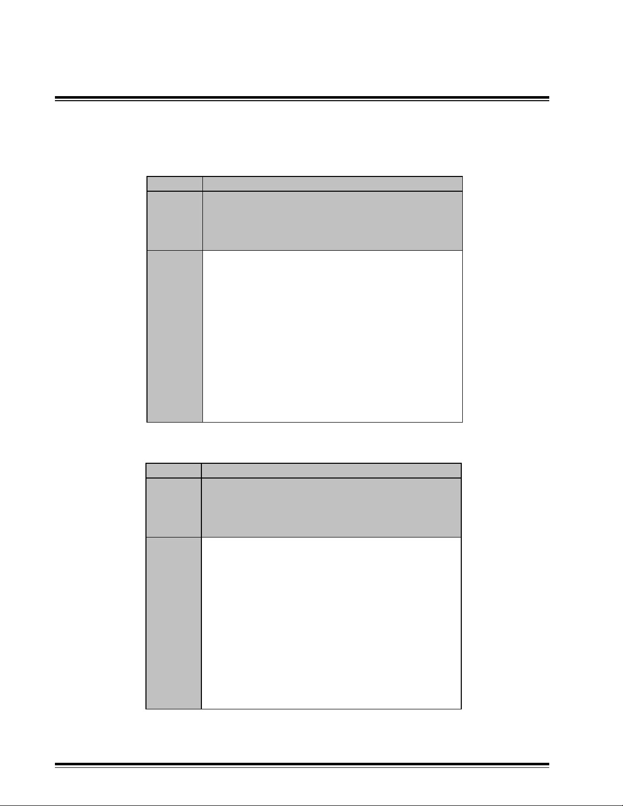
APPENDIX D
Vertical Elevation Error Caused by
Slope On Grade Deadband about Horizontal
+/- Elevation Error Caused by Slope On Grade Deadband (in)
Slope
On Grade Distance from Laser Receiver to Furthest End of Blade (in)
Deadband
(%) (Deg) 24 48 72 96 120 144
0.3 0.2 0.04 0.07 0.11 0.14 0.18 0.22
0.4 0.2 0.05 0.10 0.14 0.19 0.24 0.29
0.5 0.3 0.06 0.12 0.18 0.24 0.30 0.36
0.6 0.3 0.07 0.14 0.22 0.29 0.36 0.43
0.7 0.4 0.08 0.17 0.25 0.34 0.42 0.50
0.8 0.5 0.10 0.19 0.29 0.38 0.48 0.58
0.9 0.5 0.11 0.22 0.32 0.43 0.54 0.65
1 0.6 0.12 0.24 0.36 0.48 0.60 0.72
1.2 0.7 0.14 0.29 0.43 0.58 0.72 0.86
1.4 0.8 0.17 0.34 0.50 0.67 0.84 1.01
1.6 0.9 0.19 0.38 0.58 0.77 0.96 1.15
+/- Elevation Error Caused by Slope On Grade Deadband (ft)
Slope
On Grade Distance from Laser Receiver to Furthest End of Blade (ft)
Deadband
(%) (Deg) 2 4 6 8 10 12
0.3 0.2 0.00 0.01 0.01 0.01 0.02 0.02
0.4 0.2 0.00 0.01 0.01 0.02 0.02 0.02
0.5 0.3 0.01 0.01 0.02 0.02 0.03 0.03
0.6 0.3 0.01 0.01 0.02 0.02 0.03 0.04
0.7 0.4 0.01 0.01 0.02 0.03 0.04 0.04
0.8 0.5 0.01 0.02 0.02 0.03 0.04 0.05
0.9 0.5 0.01 0.02 0.03 0.04 0.05 0.05
1 0.6 0.01 0.02 0.03 0.04 0.05 0.06
1.2 0.7 0.01 0.02 0.04 0.05 0.06 0.07
1.4 0.8 0.01 0.03 0.04 0.06 0.07 0.08
1.6 0.9 0.02 0.03 0.05 0.06 0.08 0.10
MCB3 Installation ManualPage 52
Page 55
Vertical Elevation Error Caused by
Slope On Grade Deadband about Horizontal
+/- Elevation Error Caused by Slope On Grade Deadband (cm)
Slope
On Grade Distance from Laser Receiver to Furthest End of Blade (m)
Deadband
(%) (Deg) 1 1.5 2 2.5 3 3.5
0.3 0.2 0.15 0.23 0.30 0.38 0.45 0.53
0.4 0.2 0.20 0.30 0.40 0.50 0.60 0.70
0.5 0.3 0.25 0.38 0.50 0.63 0.75 0.88
0.6 0.3 0.30 0.45 0.60 0.75 0.90 1.05
0.7 0.4 0.35 0.53 0.70 0.88 1.05 1.23
0.8 0.5 0.40 0.60 0.80 1.00 1.20 1.40
0.9 0.5 0.45 0.68 0.90 1.13 1.35 1.58
1 0.6 0.50 0.75 1.00 1.25 1.50 1.75
1.2 0.7 0.60 0.90 1.20 1.50 1.80 2.10
1.4 0.8 0.70 1.05 1.40 1.75 2.10 2.45
1.6 0.9 0.80 1.20 1.60 2.00 2.40 2.80
APPENDIX D
MCB3 Installation Manual Page 53
Page 56

APPENDIX E
Upgrading the MCB3 Firmware
The Futtura MCB Center software is used to load new loader and application rmware to the
MCB3 control box.
Instructions are included with the upgrade package.
MCB3 Installation ManualPage 54
Page 57

NOTES
MCB3 Installation Manual Page 55
Page 58

NOTES
MCB3 Installation Manual Page 56
Page 59

NOTES
Page 57
MCB3 Installation Manual
Page 60

Futtura Tools & Technologies, Inc.
100 N Rockwell Ste 96
Oklahoma City, OK 73127 USA
 Loading...