

Page 1
Operating Manual
Original Instructions
D443236XA
vers. 2.0
F
F
UTURA
UTURA
EN
Page 2

(c) 2014 SILCA S.p.a. - Vittorio Veneto
This manual has been drawn up by SILCA S.pA.
All rights reserved. No part of this publication can be reproduced or circulated by any means whatsoever (photocopies, microfi lm or other)
without the consent of SILCA S.p.A.
Edition: April 2014
Printed at Vittorio Veneto
Da SILCA S.p.a.
Via Podgora, 20 (Z.I.)
31029 VITTORIO VENETO (TV) - Italy
The Manufacturer declines any responsibility for possible inaccuracies in this document due to printing or transcription errors. The Manufacturer
reserves the right to alter the information without prior notice, except when they affect safety. This document or any of its parts cannot be copied,
altered or reproduced without written authorization from the Manufacturer. Keep the manual and look after it for the entire life cycle of the machine.
The information has been drawn up by the manufacturer in his own language (Italian) to provide users with the necessary indications to use the keycutting machine independently, economically and safely.
IMPORTANT NOTE: in compliance with current regulations relating to industrial property, we hereby state that the trade-marks or trade names
mentioned in our documentation are the exclusive property of authorized manufacturers of locks and users.
Said trade-marks or trade names are nominated only for the purposes of information so that any lock for which our keys are made can be rapidly
identifi ed.
Page 3

INDICE
USE OF THE MANUAL ....................................................................................................................... 1
GENERAL WARNINGS ....................................................................................................................... 4
1 MACHINE DESCRIPTION ............................................................................................................................5
1.1 Main OPERATING parts ..................................................................................................................... 6
1.2 Safety 7
1.3 Technical Data ....................................................................................................................................8
1.4 ACCESSORIES PROVIDED ..............................................................................................................9
2 HANDLING ..................................................................................................................................................10
2.1 Packing .............................................................................................................................................10
2.2 Unpacking ......................................................................................................................................... 10
2.3 Handling the machine .......................................................................................................................10
3 MACHINE INSTALLATION AND PREPARATION ....................................................................................... 11
3.1 CHECKING FOR DAMAGE .............................................................................................................. 11
3.2 ENVIRONMENTAL CONDITIONS .................................................................................................... 11
3.3 POSITIONING .................................................................................................................................. 11
3.4 SEPARATE PARTS ...........................................................................................................................12
3.4.1 Tablet stand and tablet ........................................................................................................... 12
3.4.2 Power pack and lead .............................................................................................................. 13
3.4.3 Fixing bracket .........................................................................................................................13
3.5 Work station description ...................................................................................................................14
4 TABLET REGULATION AND USE ..............................................................................................................15
4.1 CHOICE OF LANGUAGE ................................................................................................................. 15
5 CLAMPS .....................................................................................................................................................17
5.1 Clamps for FLAT KEYS WITH STANDARD CUTS - 01V .................................................................17
5.1.1 Use of the gauge ....................................................................................................................18
5.1.2 Stop positions (key stop) ........................................................................................................19
5.1.3 Use of pins - CLAMP 01V ......................................................................................................19
5.1.4 Cutting cruciform keys (with 3 fi ns) .........................................................................................20
5.1.5 Removing/fi tting the clamp 01V ..............................................................................................21
5.2 CLAMP FOR DIMPLE AND TRACK KEYS - 01R .............................................................................22
5.2.1 DIMPLE keys ..........................................................................................................................22
5.2.2 TRACK type keys ...................................................................................................................23
5.3 Removing/fi tting clamp 01R .............................................................................................................23
5.4 Removing/fi tting the jaws on clamp 01R ..........................................................................................24
5.5 Using tracer 01T ...............................................................................................................................25
6 CLEANING .................................................................................................................................................. 26
7 MAINTENANCE .......................................................................................................................................... 27
7.1 OPERATIONS ...................................................................................................................................27
7.2 ACCESS TO REAR COMPARTMENT .............................................................................................27
7.3 PRISMATIC CUTTER REPLACEMENT ..........................................................................................28
Page 4

7.4 CYLINDRICAL CUTTER AND/OR TRACER POINT REPLACEMENT ............................................29
7.5 TRACER 01T REPLACEMENT ........................................................................................................ 29
7.6 CHECKING AND REPLACING FUSE .............................................................................................. 30
7.7 BATTERY REPLACEMENT ..............................................................................................................31
8 DECOMMISSIONING .................................................................................................................................32
9 ASSISTANCE ..............................................................................................................................................33
9.1 HOW TO REQUEST SERVICE ........................................................................................................ 33
10 ELECTRICAL DIAGRAMS ......................................................................................................................... 34
SOFTWARE GUIDE .................................................................................................................................... 1SW
Page 5
USE OF THE MANUAL
This manual has been drawn up by the Manufacturer and is an integral part of the machine literature.
The manual gives information it is obligatory for the operator to know and which makes it possible to use the
machine safely.
User’s Manual
This user’s manual is provided because it is essential for proper use and maintenance of the machine.
The manual must be kept carefully throughout the life of the machine, including the decommissioning stage. Keep
in a dry place close to the machine where it is always to hand for the operator.
IT IS OBLIGATORY to read the manual carefully before using the machine.
Readers’ characteristics
This manual must be read and its contents acquired by those who will use it.
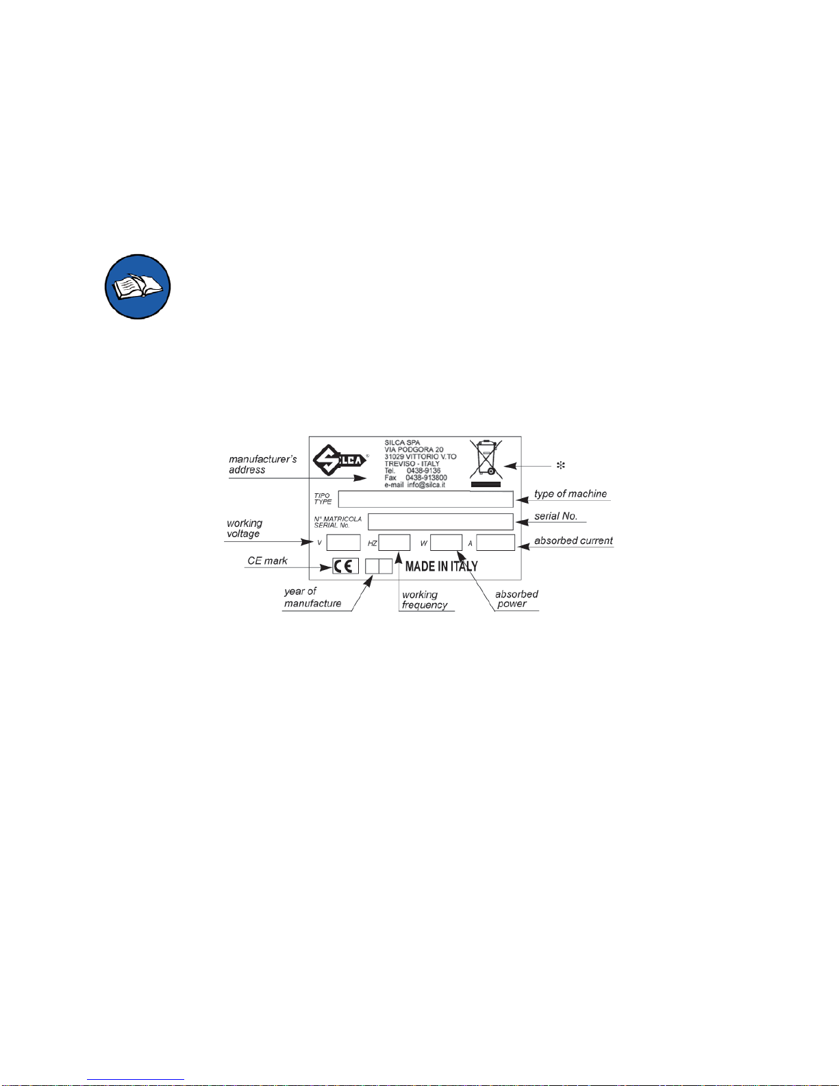
Manufacturer’s ID
FUTURA has an ID plate located on the back of the machine, showing the serial number.
Fig. 1
(*) see chap. 8 DECOMMISSIONING.
How to apply for after-sales service
Silca provides purchasers of FUTURA with After-Sales Service.
For the total safety of the operator and machine, any operation not described in the manual must be carried out
by the manufacturer or in the special Service Centres recommended by Silca.
At the end of the manual there is a list of manufacturers’ and authorized Service Centre addresses.
The warranty card attached to the machine covers free repairs or replacement of faulty parts for 24 months from
the date of purchase*. All operations must be agreed by the user with Silca or the Service Centre.
* Damage caused by negligence or wrong use of the machine by the user will null the warranty.
Operating manual
Copyright Silca 2014
1
Page 6

TERMINOLOGY
For those inexperienced in the subject of keys and key cutting, below is an illustration of the most frequently used
terms:
1
7
7
9
8
2
3
3
2
3
4
4
4
5
5
5
5
6
1 1 1
10
3
1
Fig. 2
1) Head
2) Neck
3) Stop
4) Blade (stem)
5) Tip
6) Back
7) STANDARD cutting
8) DIMPLE cutting
9) TRACK cutting
10) Stem
Operating manual FUTURA
Copyright Silca 2014
2
Page 7

GRAPHICS IN THE MANUAL
Pay attention
Obligation to read
the manual
QR* code
GRAPHICS ON THE FUTURA KEY-CUTTING MACHINE
Do not clean with
compressed air
Obligation to read
the manual
QR* code
Adhesive label
Mass - RPM
Laser warning labels
(*) A QR code is a two dimensional bar code used to memorize information to be read by means of a mobile phone
or smart phone. Read the QR code on the machine to connect to useful and constantly updated information relating
to key-cutting machine maintenance, useful tips for your FUTURA key-cutting machine and see the continuously
evolving range of optional accessories.
Operating manual FUTURA
Copyright Silca 2014
3
Page 8

GENERAL WARNINGS
FUTURA is designed to the principles of European Standards (CE).
Right from the design stage solutions have been adopted to eliminate hazards for the operator in all the stages
of use: handling, regulation, use and maintenance.
The materials used in manufacture and the components employed in using FUTURA are not dangerous and
ensure that the machine complies to current standards.
Silca S.p.A. has also experimented and applied numerous technical solutions that allow the key-cutting machine
to optimize the quality of the cut keys.
To guarantee maintaining these results over time, please follow the instructions below:
• Observe the procedures described in this manual;
• Always use Original Silca T ools as they are designed to make the best of FUTURA and provide
quality key-cutting;
• Use Silca key blanks, made with top quality materials;
• Have the key-cutting machine checked periodically by an authorized Silca After-Sales Service
Centre (list at the end of this manual);
• Always use Silca Original Spare Parts. Beware of imitations!
NORMAL USE
FUTURA is a key-cutting machine and must be installed and used according to the rules and specifi cations
established by the manufacturer.
The FUTURA key-cutting machine is designed for use on business or industrial premises (e.g. hardware shops,
key cutting centres, etc...).
Any other use different from that indicated in this manual will cause the forfeiture of all customers’ rights to make
claims on Silca S.p.A. and may be an unknown source of hazard for the operator or third parties.
ATTENTION: Negligent use or failure by the operator to observe the instructions in this
manual are not covered by the warranty and the manufacturer declines any responsibility in
such cases.
RESIDUAL RISKS
No further risks will arise when properly using the FUTURA machine.
SAFETY REGULATIONS
• Always disconnect the machine when it is not in use or when performing maintenance
operations.
• Check the electrical wiring periodically; replace any wires that show signs of wear.
• Always work with dry hands free of grease or oil.
• Never tug on the electricity supply lead and make sure it is not in contact with oil or other
liquids, sharp objects or heat. Never remove the earthing pin from the plug. Check that the
earthing wire is connected properly.
• Do not use the machine in dangerous environments (wet or damp).
• All visitors, especially children, must stay at a safe distance from the machine and must
never come into contact with the electric wiring.
Operating manual FUTURA
Copyright Silca 2014
4
Page 9

1 MACHINE DESCRIPTION
FUTURA is an electronic machine operating on 3 axes with controlled movement.
Accurately studied, it adds a high degree of cutting precision to operating speed and ease of use.
FUTURA operates only when connected to a TABLET containing a Silca program.
It uses a laser reader to read and/or codify fl at keys with standard cuts.
It uses a tracer to decode keys with dimple and/or track cuts.
It can cut keys (in ferrous materials in general, brass, silver nickel, etc.) having:
• Standard cuts
• Dimple cuts
• Track cuts
• Special cuts (e.g. Ford Tibbe - with optional accessory)
• Cuts on tubular keys (with optional acces)
FUTURA is used to cut the following types of keys:
Keys with STANDARD CUTS
Fig. 3
Keys with DIMPLE and/or TRACK CUTS
Fig. 4
Operating manual FUTURA
Copyright Silca 2014
5
Page 10

1.1 MAIN OPERATING PARTS
K
T
S
P
Q1
Q2
R
P1
H
F
A
B
Z
M
C
G
J
J1
L
U
E
G1
I2
M1
I
D
Fig. 5
A
- Tablet stand
B
- Tablet
C
- Safety shield
D
- Lamp
E
- Cover
F
- Prismatic cutter (Standard cuts)
G
- Cutter (Dimple/Track cuts)
G1
- Cutter shaft (Dimple/Track cuts)
H
- Optic reader
I
- Gauge
I2
- Gauge sensor
J
- Tracer 01T
J1
- Tracer movement lever
L
- Tool compartment
K
- Swarf collection tray
M
- Clamp 01V (Standard cuts)
M1
- Clamp knob (01V)
P
- Clamp 01R (Dimple/Track cuts)
P1
- Clamp knob (01R )
Q1
- Left-hand jaw
Q2
- Right-hand jaw
R
- ON/Emergency push button
S
- X axis carriage
T
- Y axis carriage
U
- Z axis carriage
V
- Ethernet port
W
- Power pack
W1
- Power pack connector
Y
- USB port
Z
- Tool holder
V
W1
Y
W
Fig. 6
Operating manual FUTURA
Copyright Silca 2014
6
Page 11
1.2 SAFETY
FUTURA is entirely built in compliance to the Machine Directives. The operations for which it has been designed
are easily carried out with no risk to the operator.
The adoption of general safety precautions and observation of the instructions provided by the manufacturer in
this manual eliminate all human error, unless deliberate.
FUTURA is designed with features which make it completely safe.
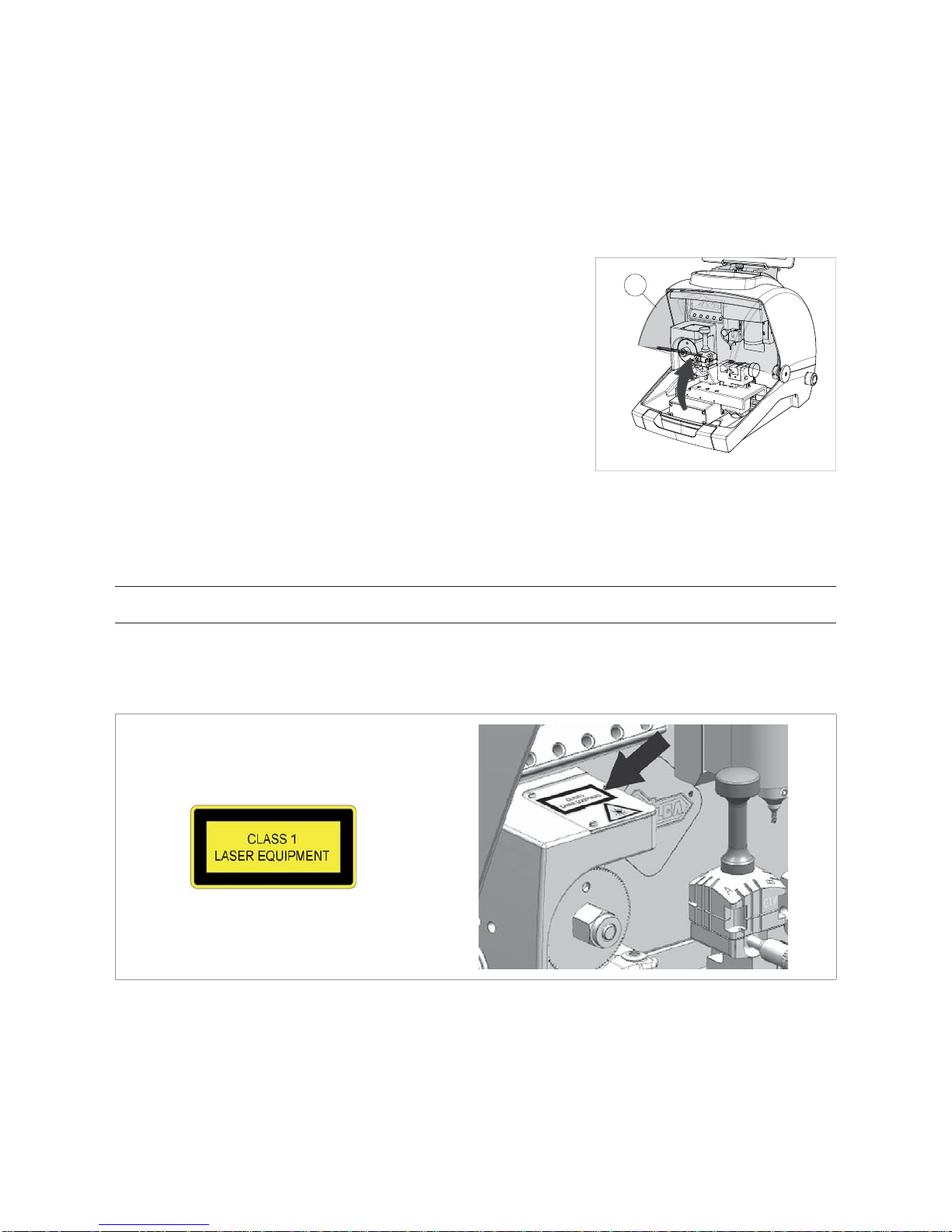
• Safety shield
The protective shield is designed to cover the working parts as completely
as possible, ensuring operator safety.
The shield (C) must be raised in order to fi t keys for cutting or carry out
other operations (Fig. 7).
Raising the shield by means of a microswitch will deactivate the operating
and movement functions, including the cutter, and failed shield closing will
be notifi ed with a special message on the tablet.
To re-activate the work cycle, lower the shield and follow the instructions
on the tablet.
Fig. 7
• Emergency stop
Use the red emergency button (R) (Fig. 5), located on the right-hand side of the machine to stop the machine
immediately in the event of serious malfunctioning or a hazard for the operator.
When the cause of the emergency has been eliminated, turn the button 45° clockwise to disactivate it.
NOTE: the operator is responsible for keeping the area around the button clear so that it can be
reached as quickly as possible.
• Laser warning
Regulations require that warning label (supplied - chap.1.4) in the language to be used be attached to the optical
reader, as shown in Fig. 8.
Fig. 8
C
Copyright Silca 2014
7
Page 12

1.3 TECHNICAL DATA
Electricity supply: Machine: 24V d.c. - 2,2 Amp. - 55W
Power pack: 90/264V a.c. - 50/60Hz - 120W - MEANWELL
GS120A24-P1M
Cutter motor (Standard cuts): 24V d.c.
Cutter motor (Dimple/Track cuts): 24V d.c.
Prismatic cutter (Standard cuts): in HSS super rapid steel, coated
Cutter (Dimple cuts): in HSS Super Rapid steel
Cutter (Track cuts): in HSS Super Rapid steel, coated
Tool speed: prismatic cutter (Standard cuts): 1100 rpm
cutter (Dimple/Track cuts): 7000 rpm
Movement: on 3 axes (with special bushes) driven by step motors (on rectifi ed
roller guides)
Clamp 01V :
(for standard cuts)
removable, with 4 universal sides for holding fl at keys, vehicle keys
and cruciform keys
Clamp 01R
(for Dimple/Track cuts)
removable and provided with interchangeable jaws
Runs: X axis: 30 mm Y axis: 50 mm Z axis: 27 mm
Dimensions: width: 318 mm
depth: 413 mm
height with tablet and stand: 522 mm (340 mm without tablet and
stand)
Mass: Kg. 20
Noise level: sound pressure Lp(A) =
-
brass fl at keys: 72.0 dB(A)
-
steel fl at keys: 74.5 dB(A)
-
brass dimple keys: 70.0 dB(A)
-
brass track keys: 74.0 dB(A)
-
steel track keys: 75.0 dB(A)
CLASS 1 LASER READER:
• Maximum radiation with safety lock excluded: 230 μW
• Wave length: 790,6 μm (invisible)
• Classed to: EN 60825-1 2007
Operating manual FUTURA
Copyright Silca 2014
8
Page 13

1.4 ACCESSORIES PROVIDED
FUTURA comes with a set of accessories for its operation and maintenance (tools, hex wrenches...) supplied in
a special tool kit comprising:
stop bar cutter 01D 2 mm allen key
ø 1,7 mm steel pin tracer point 02T 2,5 mm allen key
ø 1,2 mm steel pin universal adapter 3 mm allen key
slanted brush cutter release rod “T” allen key 2,5 mm
laser warning label 19 mm spanner template Z3 (regulating key)
fuses 4 Amp.- delayed stylus touch pen
Cutters and tracers on machine:
cutter 01F fresa 01L tracer point 01T
Separately:
Fixing bracket
01D
02T
Operating manual FUTURA
Copyright Silca 2014
9
Page 14

2 HANDLING
The FUTURA key-cutting machine is easy to handle and there are no special hazards involved in moving it.
The packed machine can by carried manually by one person.
2.1 PACKING
The packing for the FUTURA key-cutting machine ensures safe handling of the
machine and all its components.
Packing comprises expanded plastic material wrapped around the machine.
The robust cardboard box in which it is placed and the nylon wrapping protect
the machine even when stored for a long period.
Fig. 9
Keep dry Handle with care Up
The symbols on the outside of the cardboard box give indications for transport.
ATTENTION: keep the complete packing for future machine transfers.
2.2 UNPACKING
To remove the machine from its packing:
1) Cut the strapping with scissors and remove.
2) Open the box carefully without damaging it.
3) Free the machine from the protective shells.
4) Check the contents of the packing, comprisingda:
-
FUTURA key-cutting machine
-
documentation comprising: user’s manual, spare parts sheet, specialist guide and warranty
-
tablet
-
tablet stand
-
power lead
-
power pack
-
tool kit
-
fi xing bracket
2.3 HANDLING THE MACHINE
Once removed from its packing place FUTURA directly on the work bench; one person can easily perform this
operation.
A TTENTION: lift the machine by holding onto the base. Never lift the machine by gripping the
clamps, levers or other parts.
Operating manual FUTURA
Copyright Silca 2014
10
Page 15

3 MACHINE INSTALLATION AND PREPARATION
Installation is the customer’s task and does not require any special skills.
The key-cutting machine is supplied ready for use and does not need calibration except for the tools to be used;
however, the operator is required to make certain checks and prepare the machine for use.
3.1 CHECKING FOR DAMAGE
FUTURA is a solid compact machine and will not break if handling, unpacking and installation are carried out to
the instructions in this manual. However, it is good practice to check that the machine has not been damaged.
3.2 ENVIRONMENTAL CONDITIONS
To make the most of the key-cutting machine, bear in mind the following environmental parameters: it is advisable
for the area to be dry with good air circulation.
The optimum environmental conditions for machine operation are:
- temperature 10° C to 40°C;
- relative humidity: approx 60%.
3.3 POSITIONING
1) Place the key-cutting machine on a solid horizontal work bench suitable for the weight of the machine (20
Kg). The work bench should be approximately 100-120 cm high to facilitate access to the working parts. We
recommend leaving at least 30 cm clearance behind and around the machine to ensure good ventilation and
facilitate handling (Fig. 10).
2) Make sure machine voltage is suitable for the mains supply and that the latter is earthed with a differential
switch.
3) Connect the power lead (power pack) to the machine (chap.3.4.2).
100/120 cm
30 cm
30 cm
30 cm
Fig. 10
Operating manual FUTURA
Copyright Silca 2014
11
Page 16

3.4 SEPARATE PARTS
The machine packing also contains the following components, separately packed:
3.4.1 Tablet stand and tablet
Fig. 11 Fig. 12
These items are separate from the machine and must be unpacked and installed by the operator in the way
described below:
1) Remove the 2 items from their packing.
2) Loosen the knob on top of the machine cover (Fig. 13).
3) Install the tablet stand so that the special profi le fi ts into the slot on the machine cover (Fig. 14).
4) Screw down and tighten the knob to secure the tablet stand to the cover (Fig. 15).
5) Fit the tablet into its stand (Fig. 16).
Fig. 13 Fig. 14
Fig. 15 Fig. 16
6) Connect the tablet USB/Micro USB cable to the special receptacle and then to the power supply.
Operating manual FUTURA
Copyright Silca 2014
12
Page 17
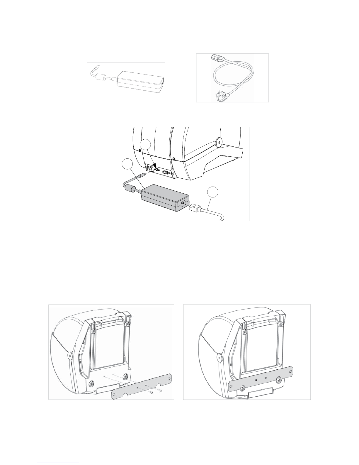
3.4.2 Power pack and lead
Fig. 17 Fig. 18
Connect FUTURA to the power pack (W) and connect the latter to the power supply with the power lead (W2).
W
W2
W1
Fig. 19
3.4.3 Fixing bracket
If the key-cutting machine is transported and used on a vehicle, e.g. a van, it must be prepared as follows:
1) Turn off the machine and detach the power lead.
2) Remove the tablet holder and tablet.
3) Turn the key-cutting machine onto its back.
4) Connect the fi xing bracket to the machine and secure with the 2 screws.
5) Return the machine to its upright position on the work top.
Fig. 20 Fig. 21
Operating manual FUTURA
Copyright Silca 2014
13
Page 18

3.5 WORK STATION DESCRIPTION
One operator is enough to operate the machine, which has the following operating parts:
• General ON/OFF/emergency button (R) located on the right-hand side of the machine
• Key holding clamps (M) (P)
• Tablet (B)
• Tablet ON button (B1)
• Safety shield (C)
• Cutters (F) (G)
P
R
B
M
C
G
F
B1
Fig. 22
Operating manual FUTURA
Copyright Silca 2014
14
Page 19

4 TABLET REGULATION AND USE
1) Connect the tablet to the mains by means of its power pack in order to charge it (3 hours for the fi rst charge).
2) Turn on the tablet by holding down the push button (B1) (Fig. 22) holding it down for a few seconds.
REGULATING TABLET INCLINATION TABLET
1) Loosen the knob (B2).
2) Incline the stand as required.
3) Tighten the knob (B2).
Fig. 23
4.1 CHOICE OF LANGUAGE
1) Select “Settings”.
Operating manual FUTURA
Copyright Silca 2014
15
Page 20

2) Scroll up with your fi nger.
3) Select Language & Input and then Language (on the right).
4) Scroll and select the required .
5) To quit:
• For all Silca key-cutting machine software functionalities follow the instructions in the SOFTWARE Guide
section in this manual.
• Further instructions are given in the quick guide for the tablet.
Operating manual FUTURA
Copyright Silca 2014
16
Page 21

5 CLAMPS
5.1 CLAMPS FOR FLAT KEYS WITH STANDARD CUTS - 01V
The use of one of the clamp sides is required, according to the type of key to be decoded and/or cut by copying
or by code (Fig. 25). Positioning the correct side to be used is quick and easy. With the clamp jaws slightly open,
turn the clamp by hand to position it as required, facilitated by a new special alignment system (Fig. 26).
Fig. 24 Fig. 25
The 4-sided clamp is used to secure keys fi rmly up against the back and on the profi le.
• To copy keys (these can be locked on any of the clamp sides A, B, C or D), the user will decide which side is
the most suitable.
• For code key-cutting the choice of clamp to use is established by the software.
Fig. 26 - CLAMP ROTATION
Operating manual FUTURA
Copyright Silca 2014
17
Page 22

5.1.1 Use of the gauge
The gauge is used to position fl at cylinder or vehicle keys with Stop 0 (Fig. 33).
Fig. 27 Fig. 28 Fig. 29
I2
I3
Fig. 30 Fig. 31 Fig. 32
Pull the gauge gently towards the operator, turn clockwise by about 180° and release against the clamp.
Fit the sample key into the clamp with the stop up against the gauge.
Use the bar (provided) to align the tip of keys without stops (Fig. 34).
The choice of position 1-2-3-4 depends on the length of the cut.
NOTE: take the gauge back by hand to its original position before starting to read or cut the key (Fig.
32).
For all reading/decoding and cutting operations the gauge (I) must be taken back manually to its original position
(Fig. 32 - in this position it covers the sensor (I2) which detects it).
To take the gauge to its original position (with the gauge up against the key stop) proceed as follows:
1) Turn anti-clockwise;
2) Pull towards the operator and continue to rotate anti-clockwise until it comes up against the stop pin (I3);
3) Release the gauge.
Operating manual FUTURA
Copyright Silca 2014
18
Page 23

5.1.2 Stop positions (key stop)
0
123 4
Fig. 33 - HEAD STOP (Stop 0) Fig. 34 - TIP STOP
• To fi t keys with tip stops into the clamps, fi t the bar provided into the grooves (Fig. 34) or up against the right-
hand side of the clamp.
NOTE: the stop bar must be removed before decoding or cutting.
ATTENTION: it is not necessary to apply force to close the clamp properly.
5.1.3 Use of pins - CLAMP 01V
For keys with narrow stems the pins must be placed
between the bottom of the clamp and the back of the key
so that the key protrudes suffi ciently out of the clamp and
therefore can be properly read and cut.
If the key has a narrow stem and is also very thin, 2 pins
must be used (Fig. 35).
Fig. 35
If the original key is broken, place a suitable sized pin in the groove of the keys stem so that it is properly held in
place and therefore can be copied (Fig. 36).
NOTE: use a pin with the same diameter for both decoding and cutting.
Fig. 36 Fig. 37
Operating manual FUTURA
Copyright Silca 2014
19
Page 24

5.1.4 Cutting cruciform keys (with 3 fi ns)
The standard 4-sided clamp can be used to cut almost all cruciform keys (except for Y and T shaped ones).
1) Leave the gauge in its original position.
2) Fit the key into the clamp:
- Insert the grooved bar into the notch on the clamp according to the key stop (as shown in Fig. 38 - Key stop
towards the inner part of the clamp, Fig. 39 - Key stop DOWN and Fig. 40 - Key stop UP).
- Butt the key stop up against the bar.
3) Tighten the knob (M1) to secure the key.
4) Remove the bar.
ATTENTION: the cuts on each fi n are different.
POSITION OF KEY AND BAR
Fig. 38 - Key stop towards the INNER PART of the clamp
Fig. 39 - Key stop DOWN
Fig. 40 - Key stop UP
Operating manual FUTURA
Copyright Silca 2014
20
Page 25

5.1.5 Removing/fi tting the clamp 01V
1) Raise the safety shield.
2) Unscrew the knob (M1) and remove together with the washer set (Fig. 41).
3) Pull the clamp upwards (Fig. 42).
4) Carefully clean the seat of the clamp support.
5) Clean the clamp before fi tting into the support.
6) Tighten the knob (M1) with the washer set.
M
Fig. 41 Fig. 42
Operating manual FUTURA
Copyright Silca 2014
21
Page 26

5.2 CLAMP FOR DIMPLE AND TRACK KEYS - 01R
According to the type of key to be decoded and/or cut, follow the instructions in the Silca tablet program regarding:
• clamp
• use of jaws (Q1) and (Q2)
• clamp stop (Fig. 44 and Fig. 45)
FITTING THE KEY
The clamp is designed to house high security keys with stop or tip
reference.
The former (with stop) must be placed up against the jaws (stop “0”)
(Fig. 44) and the others (tip stop) must be placed against one of the
grooves (1-2-3-4), as indicated in the Silca tablet program. For this
operation use the bar provided (Fig. 45).
NOTE: the stop bar must be removed before decoding or
cutting.
1) Fit the key to be cut into its seat and ensure it is resting fi rmly on
the clamp plate.
2) Tighten the knob (M) to secure the key.
Fig. 43
5.2.1 DIMPLE keys
0
Fig. 44 - HEAD STOP
1
2
3
4
Fig. 45 - TIP STOP
Q2Q1
Operating manual FUTURA
Copyright Silca 2014
22
Page 27
5.2.2 TRACK type keys
0
Fig. 46 - HEAD STOP
1
2
3
4
Fig. 47 - TIP STOP
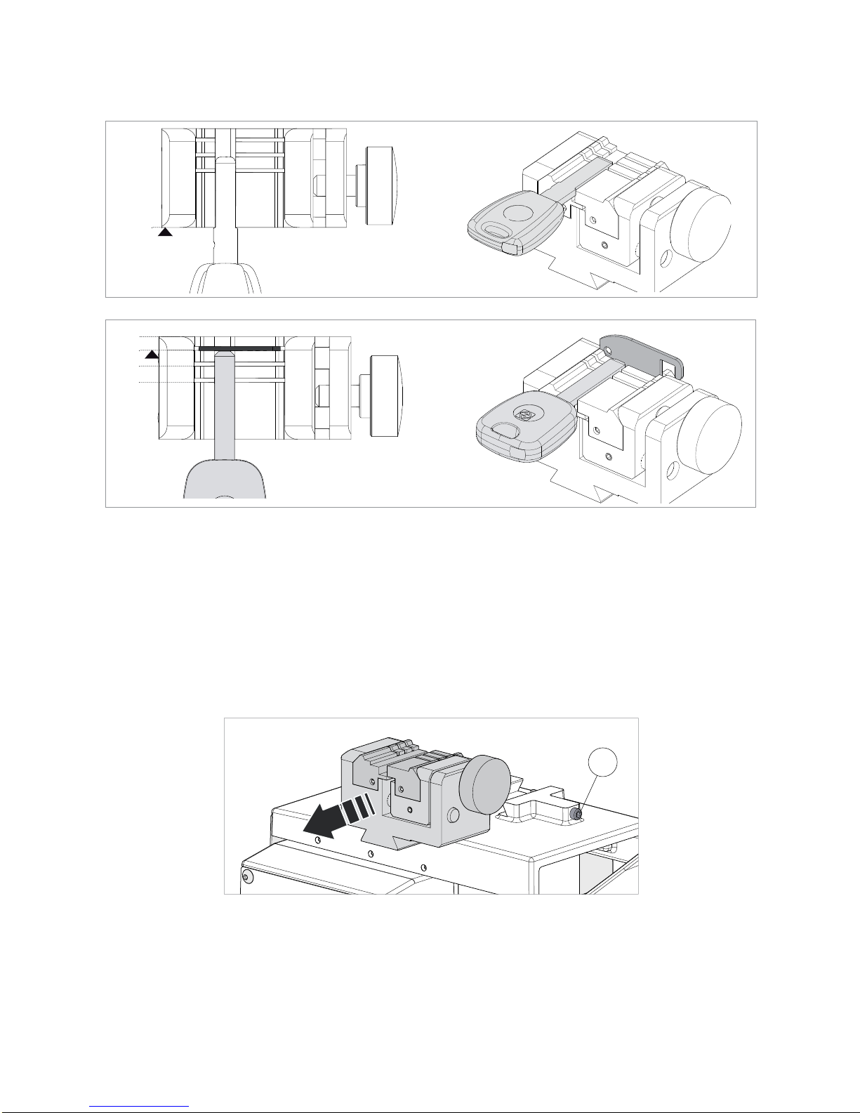
5.3 REMOVING/FITTING CLAMP 01R
1) Raise the safety shield.
2) Loosen the grub screw (P2) and remove the clamp by pulling it towards the operator.
3) Carefully clean the clamp support seat.
4) Clean the clamp before fi tting into the support.
5) Fit the clamp (with knob on the right) into the special dovetail and take up against the stop pin.
6) Tighten the grub screw (P2) to secure the clamp.
P2
Fig. 48
Operating manual FUTURA
Copyright Silca 2014
23
Page 28

5.4 REMOVING/FITTING THE JAWS ON CLAMP 01R
1) Raise the safety shield.
2) Loosen the knob (P1) by a couple of turns (Fig. 49).
3) Use your fi ngers to push the jaw to be removed from behind the clamp, pulling out towards the operator (Fig.
50).
4) Carefully clean the seat of the jaw on the clamp.
5) Clean the jaw before fi tting into the clamp.
6) Fit the jaw up against the stop pin.
NOTE: there is only one way to fi t the jaw into the clamp.
P
1
Fig. 49 Fig. 50
Operating manual FUTURA
Copyright Silca 2014
24
Page 29

5.5 USING TRACER 01T
The tracer 01T is used to read/decode both dimple and track keys.
This tracer may or may not be required according to the type of key to be decoded and the
dimensions involved.
Fig. 51
• ACTIVATING THE TRACER 01T
To use the tracer: move the lever (J1) to the left in order to lower the tracer.
• EXCLUDING THE TRACER 01T
To take the tracer to the idle position: raise the lever (J1) and move it to the right.
Fig. 52 Fig. 53
You may be required to use the 02T tracer (provided), to be fi tted into the cutter shaft (Fig. 55).
Note: fi t the new tracer pushing all the way upwards.
02T
Fig. 54 Fig. 55
NOTE: for cutting and/or decoding operations with the tracer point 02T , the tracer 01T must be in the
idle position (Fig. 53).
Operating manual FUTURA
Copyright Silca 2014
25
Page 30

6 CLEANING
• Keep the operational parts of the machine as clean as possible by brushing away the
chippings in areas where they accumulate during cutting operations.
• Under no circumstances must compressed air be used to clear the work zone of chippings
as this will blow them onto the moving parts.
• Never use oily products or thinners for cleaning painted surfaces, clamps, electrical or
electronic connections.
Operating manual FUTURA
Copyright Silca 2014
26
Page 31

7 MAINTENANCE
A TTENTION: for repairs or replacement of parts for maintenance, the ‘CE’ mark is guaranteed
only if original spare parts provided by the manufacturer are used.
The FUTURA key-cutting machine does not need special maintenance, but it is good practice to check and if
necessary replace parts subject to wear: cutter, tracer point, belt.
Replacement operations are simple and can be performed by the operator.
ATTENTION: DO NOT USE COMPRESSED AIR!
ATTENTION: to maintain machine effi ciency we recommend using protective oil such as
WD40 or similar to apply to the burnished mechanical parts. Make sure the oil does not come
into contact with the electronic parts.
Before performing any type of maintenance (checks or replacements) read the warnings below:
• Do not perform any maintenance operations with the machine on.
• Always disconnect the power lead.
• Follow the instructions in the manual carefully.
• Use original spare parts (see provided spare parts sheet).
7.1 OPERATIONS
• Access to rear compartment
• Prismatic cutter replacement
• Cylindrical cutter and/or tracer point replacement
• Tracer 01T replacement
• Checking and replacing fuse
• Battery replacement
7.2 ACCESS TO REAR COMPARTMENT
1) Turn off the key-cutting machine and disconnect the power lead.
2) Remove the tablet.
3) Loosen the 2 screws (E1) and the 2 screws (E2).
4) Rotate the cover towards the front of the machine.
ATTENTION with the tablet USB cable.
E2
E1
E2
Fig. 56 Fig. 57
Operating manual FUTURA
Copyright Silca 2014
27
Page 32

7.3 PRISMATIC CUTTER REPLACEMENT
1) Raise the safety shield.
2) Rotate the cutter by hand to align the cutter slot with the rear slot (on the reader stand).
3) Insert the pin (F1) (provided with the machine) into the 2 slots.
4) Loosen the nut (F2) clockwise.
ATTENTION: the thread is to the left.
5) Remove the nut, pin and cutter.
6) Carefully clean the cutter shaft seat and the new cutter.
7) Fit the new cutter and align the cutter slot with the rear slot (on the reader stand).
8) Insert the pin (F1) (provided with the machine) into the 2 slots.
9) Tighten the nut (F2) anticlockwise. Attention: the thread is to the left.
ATTENTION: when fi tting a new cutter to replace a worn one, or when fi tting a re-sharpened
one, see ch.5.2 of the Software guide.
F2
F1
Fig. 58 Fig. 59
Fig. 60
Operating manual FUTURA
Copyright Silca 2014
28
Page 33

7.4 CYLINDRICAL CUTTER AND/OR TRACER POINT REPLACEMENT
1) Raise the safety shield.
2) Rotate the cutter shaft (G1) by hand and take the grub screw (G2) to the front of the machine.
3) Use a hex key to loosen the grub screw (G2) and remove the tool.
4) Fit the new tool, pushing all the way upwards.
5) Tighten the grub screw (G2) to secure the tool.
G2
G1
Fig. 61 Fig. 62
7.5 TRACER 01T REPLACEMENT
1) Raise the safety shield.
2) Move the lever (J1) to the left to lower the tracer.
3) Use a hex key to loosen the grub screw (J2) and remove the tracer.
4) Fit the new tracer, pushing all the way upwards.
5) Tighten the grub screw (J2) to secure the tracer.
J2
J1
Fig. 63 Fig. 64
Operating manual FUTURA
Copyright Silca 2014
29
Page 34

7.6 CHECKING AND REPLACING FUSE
Fuses should be checked with a tester (ohmmeter, multimeter, etc.) as they may appear to be in good condition
even when they are electrically faulty. Fuses must always be replaced with the same amperage and type (rapid
or delayed), as indicated in this manual
.
FUTURA has 1 fuse:
4 Amps delayed
Protects the cutters motors and their electronic controls (230V a.c.)
To check and/or replace the fuse proceed as follows.
1) Turn the machine off and unplug it from its power supply cable.
2) Access the rear compartment (chap.7.2).
To remove the fuse:
press the fuse cap with your fi ngers and turn it counter clockwise.
To fi t the new fuse:
carefully position the fuse back into place, then gently press the fuse cap downwards turning it clock wise.
To remove
To fi t
Fig. 65
Operating manual FUTURA
Copyright Silca 2014
30
Page 35

7.7 BATTERY REPLACEMENT
1) Turn the machine off and unplug it from its power supply cable.
2) Access the rear compartment (chap.7.2).
3) Use insulated screwdriver to remove the fl at battery.
4) Insert the new battery into its seat, paying attention to the poles.
ATTENTION: use the same type of lithium battery CR2032 3 Volt.
Fig. 66
Fig. 67
Operating manual FUTURA
Copyright Silca 2014
31
Page 36

8 DECOMMISSIONING
To decommission the machine it must be made unusable by:
• deactivating the power supply;
• separating the plastic parts from the metal parts.
• Remove the lithium battery from the electronic board.
ATTENTION: the lithium battery must be disposed of in the special containers.
After doing the above, dispose of the waste in compliance with the current directives in the country where the
machine is located.
Waste disposal
CEE regulations lay down special methods for disposing of waste (**).
Machine
FUTURA is not only a durable machine, but is also re-usable.
Recycling is a good environmentally friendly practice.
Packing
The FUTURA device is consigned in a cardboard packing box which can be re-used if undamaged. When it is
to be thrown away it is classifi ed as solid urban waste and should be placed in the special paper collecting bins.
The protective shell containing the machine is in expanded polyethylene, classifi ed as SUW, and can therefore
be placed in an ordinary waste.
Waste from key-cutting
Residue deriving from key cutting is classifi ed as special waste, but can be included in solid urban waste (SUW)
as metaI scourers. This waste must be disposed of in the special collection centres according to its classifi cation
by current laws in Italy and the European Union. If it is contaminated or contains harmful-noxious substances
which transform the metal residue included in SUW into harmful-noxious substances, it is included in the lists of
the appendices to current regulations in Italy and the European Union for waste disposal.
INFORMATION TO USERS
Under the terms of art. 10 of Directive 2002/96/CE dated 27/01/2003
regarding waste from electric and electronic equipment (WEEE),
• The symbol shown above is also attached to equipment and indicates that it has been placed on the market
and must be separated and disposed of when no longer wanted (including all components, sub-assemblies
and consumables that are an integral part of the product).
• Please contact SILCA S.p.A. or any other subject on the national registers of other countries in the European
Union for information about waste disposal systems for the equipment. Household waste (or of similar origins)
can be disposed of by the separate urban waste collection system.
• When purchasing new equipment of an equivalent kind the unwanted equipment can be given back to the
dealer. The dealer will then contact the authority responsible for collecting it.
• Separate waste collection of unwanted equipment and its forwarding to treatment, recovery and environmentally
friendly disposal makes it possible to avoid potential negative effects on the environment and human health,
and assists recycling and recovery of materials.
• Unauthorized disposal of the product by the user is punished by the application of fi nes established by the
countries which have received Directives 91/156/CE and 91/689/CE.
(**)
wastes are substances or objects deriving from human activity or natural cycles which are discarded, or intended to be discarded
.
Operating manual FUTURA
Copyright Silca 2014
32
Page 37

9 ASSISTANCE
Silca provides full assistance to purchasers of the key-cutting machine. To ensure complete safety for the operator,
any job not specifi ed in this manual should be carried out by the manufacturer or in the special Service Centres
recommended by Silca.
On the back cover of this manual is a list of the manufacturer’s addresses; listed below are the addresses of
specialised Service Centres.
9.1 HOW TO REQUEST SERVICE
The guarantee attached to the key-cutting machines ensures free repairs or replacements of faulty parts within
24 months of purchase. All other service calls must be arranged by the customer with Silca or with a Silca service
centre.
Operating manual FUTURA
Copyright Silca 2014
33
Page 38

10 ELECTRICAL DIAGRAMS
J9 optic reader
J22 micro carter
+ tracer point sensor
J2 led lamp
J21 electric contact
J8 led lamp RGB
J4 power supply +24V
J5 USB port
J6 antenna
J3 ethernet port
J23 not used
J20 not used
J10 gauge sensor
J13 X axis motor
J12 X axis sensor
J15 Y axis sensor
J17 Z axis sensor
J19 not used
J16 not used
J14 Y axis motor
J18 Z axis motor
+ micro carter
J7 cutter motors
Operating manual FUTURA
Copyright Silca 2014
34
Page 39

MOTHER
BOARD J9
OPTIC READER
Laser receiver
Laser transmitter
MOTHER BOARD J13
MOTHER BOARD J14
MOTHER BOARD J18
STEP MOTOR Z AXIS
STEP MOTOR Y AXIS
STEP MOTOR X AXIS
red
light blue
green
yellow
red
white/red
green
white/green
red
white/red
green
white/green
Operating manual FUTURA
Copyright Silca 2014
35
Page 40

MOTHER BOARD J12
X AXIS SENSOR
Y AXIS SENSOR
Z AXIS SENSOR
MOTHER BOARD J15
MOTHER BOARD J17
yellow
black
light blue
brown
black
light blue
brown
black
light blue
brown
light blue
black
MOTHER BOARD J22
TRACER POINT SENSOR
MICRO CARTER
black
brown
light blue
Operating manual FUTURA
Copyright Silca 2014
36
Page 41

MOTHER BOARD J8
MOTHER BOARD J2
black
green
brown
red
light blue
light blue
black
red
LED LAMP
LED LAMP RGB
red
green
blue
MOTHER BOARD J10
MOTHER BOARD J21
GAUGE SENSOR
ELECTRIC CONTACT
Operating manual FUTURA
Copyright Silca 2014
37
Page 42

MOTHER BOARD J5
USB PORT
S1 USB
red
1
6
white
green
black
+5V
USB-DM
USB-DP
GND-USB
SHIELD
red
+24V
+/-
red
black
black
MOTHER BOARD J7
MOTHER BOARD J4
EMERGENCY PUSH BUTTON
Cutter
motor
laser
Cutter
motor
flat
Micro
carter
CUTTER MOTOR
Filter
POWER SUPPLY
24V
+ MICRO CARTER
1
2
ETHERNET
CABLE
ETHERNET PORT
ETHERNET CABLE EXTENSION
MOTHER
BOARD J3
Operating manual FUTURA
Copyright Silca 2014
38
Page 43

EN
IT DE FR ES PT NL
J2
Led lamp lampada led Led Lampe Lampe Led Lampara Led Lâmpada Led Led lamp
J3
Etherner port Porta ethernet
Ethernet-
Anschluss
Port Ethernet Puerto ethernet Porta ethernet Ethernetpoort
J4
Power feeder
+24V
Alimentatore
+24V
Speisegerat
+24V
Alimentateur
+24V
Alimentador
+24V
Alimentador
+24V
Voedingseenheid
+24V
J5
USB port Porta USB USB-Anschluss Port USB Puerto USB Porta USB USB-poort
J6
Antenna Antenna Antenne Antenne Antena Antena Antenne
J7
Cutter motor
+ micro carter
Motore fresa
+ micro carter
Motor-Fräser
+ Mikro-Carter
Moteur fraise
+ micro carter
Motor fresa
+ micro carter
Motor fresa
+ micro carter
Freesmotor
+ cover micro
J8
Led lamp RGB
Lampada Led
RGB
Led Lampe RGB
Lampe Led
RGB
Lámpara Led
RGB
Lâmpada Led
RGB
Led lamp
RGB
J9
Optic reader Lettore ottico Opticher Leser
Lecteur
optique
Lector optico Leitor optico Optische lezer
J10
Gauge sensor Sensore calibro Lehre-Fühler
Senseur
calibre
Detector calibre Sensor calibre Gauge sensor
J12
X axis sensor Sensore asse X Fuhler X-Achse Senseur axe X Detector eje X Sensor eixo X X-as sensor
J13
X axis motor Motore asse X Motor X-Achse Moteur axe X Motor eje X Motor eixo X X-as motor
J14
Y axis motor Motore asse Y Motor Y-Achse Moteur axe Y Motor eje Y Motor eixo Y Y-as motor
J15
Y axis sensor Sensore asse Y Fuhler Y-Achse Senseur axe Y Detector eje Y Sensor eixo Y Y-as sensor
J16
not used non usato nicht verwendet non utilisé no utilizado não utilizado niet gebruikt
J17
Z axis sensor Sensore asse Z Fuhler Z-Achse Senseur axe Z Detector eje Z Sensor eixo Z Z-as sensor
J18
Z axis motor Motore asse Z Motor Z-Achse Moteur axe Z Motor eje Z Motor eixo Z Z-as motor
J19
not used non usato nicht verwendet non utilisé no utilizado não utilizado niet gebruikt
J20
not used non usato nicht verwendet non utilisé no utilizado não utilizado niet gebruikt
J21
Electric
contact
Contatto
elettrico
Elektrische
Kontakt
Contact
électrique
Contacto
eléctrico
Contato
elétrico
Elektrisch
contact
J22
Micro carter +
tracer point sensor
Micro carter +
sensore tastatore
Mikro Carter +
Taster Fühler
Micro carter +
senseur palpador
Micro carter +
sensor palpador
Micro carter +
sensor palpador
Cover micro +
sensor tracer punt
J23
not used non usato nicht verwendet non utilisé no utilizado não utilizado niet gebruikt
Operating manual FUTURA
Copyright Silca 2014
39
Page 44

Page 45

SOFTWARE
SOFTWARE
OPERATING GUIDE
SOFTWARE Operating Guide FUTURA
Copyright Silca 2014
1 - SW
Page 46

INDEX
a) SOFTWARE PROGRAM ...............................................................................................................3
b) CHOICE OF KEYBOARD ..............................................................................................................4
c) CHANGE PROGRAM LANGUAGE.................................................................................................4
d) MEASURING UNITS ......................................................................................................................4
1 - SEARCHES ..........................................................................................................................................5
1.1 - STANDARD keys ............................................................................................................................5
1.2 - VEHICLE keys ................................................................................................................................5
1.3 - DIMPLE / TRACK keys ...................................................................................................................5
1.4 - Full key searching ...........................................................................................................................5
e) SEARCH PARAMETERS ...............................................................................................................6
f) KEY CUTTING ..............................................................................................................................12
2 - COPY BY ORIGINAL ..........................................................................................................................13
3 - FAVOURITES .....................................................................................................................................15
5 - OPTIONS ............................................................................................................................................16
5.1 - Info ........................................................................................................................................16
5.2 - Calibration .....................................................................................................................................17
5.2.1 - STANDARD key clamp calibration ....................................................................................17
5.2.2 - DIMPLE/TRACK keys clamp calibration ...........................................................................19
5.2.3 - MOBILE TRACER 01T calibration ....................................................................................20
5.2.4 - STANDARD key Adapter calibration .................................................................................20
5.2.5 - DIMPLE/TRACK keys Adapters calibration .......................................................................21
5.3 - SETTINGS ....................................................................................................................................22
5.3.1 - Zero-point Calibration (STANDARD key) ..........................................................................22
5.3.2 - Zero-point Calibration (DIMPLE/TRACK key) ...................................................................23
5.3.3 - Options ..............................................................................................................................25
5.3.3-a - General ................................................................................................................25
5.3.3-b - Preferences Standard key ...................................................................................27
5.3.3-c - Preferences DIMPLE/TRACK key .......................................................................28
5.3.4 - Network setting .................................................................................................................29
5.4 - MACHINE MAINTENANCE ..........................................................................................................35
6 - UPDATES ...........................................................................................................................................38
7 - BACKUP / RECOVERY ......................................................................................................................39
g) CHANGING TABLETS ..................................................................................................................40
SOFTWARE Operating Guide FUTURA
Copyright Silca 2014
2 - SW
Page 47

a) SOFTWARE PROGRAM
To start the “SKP MOBILE” program hit the icon on the tablet screen.
If the program does not start check the network settings (see Ch.5.3.4).
1- Search
Menu used to select a category of Series
Searches.
5 - Options
Menu used to set up the machine.
2 - Copy by Original
Menu used to make a copy of a key by means of
a laser reader.
6 - Upgrades
Menu used to update machine software.
3 - Favourites
Menu used to access a series of searches
previously set up as favourites.
7 - Backup | Recovery
Menu used to save machine data and restore
them when necessary.
4 - Queue of jobs
Menu used to run the job queue previously
created from the search menu.
8 - Info
Menu showing machine details.
1
2
3
4
5
6
7
8
SOFTWARE Operating Guide FUTURA
Copyright Silca 2014
3 - SW
Page 48

b) CHOICE OF KEYBOARD
When the FUTURA program is started you are required to choose the type of keyboard you will use for
entering data.
SILCA Keyboard: smaller keyboard specially designed for the Futura program.
Android (AOSP) keyboard: standard Android tablet keyboard.
If you have chosen the Silca keyboard you can go back to Android by hitting the key on the Silca keyboard.
c) CHANGE PROGRAM LANGUAGE
The default program language is English. To change language go to the Options menu (Ch.5), select
Settings
-> Options -> General -> Language and choose the language you require.
d) MEASURING UNITS
All the values given in the program for the technical measurements of keys and clamps are expressed
in hundredths of a millimetre or thousandths of an inch, according to the measuring unit chosen from the
“Options” menu.
SOFTWARE Operating Guide FUTURA
Copyright Silca 2014
4 - SW
Page 49

1 - SEARCHES
When the Searches menu is opened, the following window appears:
1.1 - STANDARD keys
Menu used to make a search restricted to the category fl at keys only (e.g.: CS207 - YA31 - UL050 ... ).
1.2 - VEHICLE keys
This menu is used to restrict a search to the category of vehicle keys only (e.g.: HU66P - GT15R - YM28T2
... )
1.3 - DIMPLE / TRACK keys
This menu is used to restrict a search to the dimple/track category of keys (e.g. CS48 - IE15 - AB48 ... ).
1.4 - Full key searching
This menu is used to make extended searches not restricted to categories.
The SEARCH menu for VEHICLE keys differs from the others in that it has 4 extra search parameters:
Vehicle make: enter the name of the vehicle manufacturer.
Model: enter the name of the vehicle model
.
Year from: enter the year the model fi rst came out
.
Year to: enter the year production of the model ceased, or leave the fi eld empty
.
See example of STANDARD keys search fl ow.
SOFTWARE Operating Guide FUTURA
Copyright Silca 2014
5 - SW
Page 50

When you enter the STANDARD keys category the following window appears for you to enter the search
parameters.
e) SEARCH PARAMETERS
Code:
enter the indirect key-cutting code
.
Card / Sn: enter the card number or serial number assigned by Silca.
Key blanks: enter the Silca key blank code or comparative
.
Key manufacturer: enter name of key manufacturer.
Cuts: enter number of cuts for the key to be included in the search
.
Lock Manufacturer: enter the brand of lock to be included in the search
.
Lock system: enter the name of the lock system
.
Press “Reset” to delete the entered fi elds
.
After entering one or more parameters, tap the “Search” button to start the search. This operation will show
the data relating to the lock systems found and information about the Silca key blank, if applicable.
Hit
on the left-hand side of the page to re-open the Search Parameters window.
SOFTWARE Operating Guide FUTURA
Copyright Silca 2014
6 - SW
Page 51

There are “3 folders” on the right of the screen:
INFORMATION: shows information about the lock make, applications and Silca key blank. Info about a
Silca key can be viewed by tapping the fi eld relating to the key blank.
APPLICATIONS: shows the applications for which this key blank is used: locks, cylinders, vehicle
model,etc.
CARD: shows information relating to accessories needed for cutting keys with the FUTURA key-cutting
machine.
In the section of the window showing
the search results
• order searches by tapping the arrow next to the relative fi elds.
• select a series from those shown, or search for it on the next pages:
• hit the special fi eld to enter the Hook position: it is automatically saved when the keyboard is turned off.
To access the cutting card select the relevant line and tap the “OPEN CUTTING CARD” button.
SOFTWARE Operating Guide FUTURA
Copyright Silca 2014
7 - SW
Page 52

Example 1: Data card for STANDARD keys
The left-hand section of the screen shows all the technical details relating to the selected cutting card (e.g.
Card, SN, Profi le, Series, Spaces, Depth, Cutting angle).
The right-hand part contains the functions listed below:
Code:
enter the indirect code for cutting the key.
Cuts: this function is used to enter direct cuts.
*
SOFTWARE Operating Guide FUTURA
Copyright Silca 2014
8 - SW
Page 53

Decoding: used to decode the cuts on the original key
.
Hit “Decoding”: information appears regarding the position of the key in the clamp.
To continue hit START and perform the operations described on the screen.
At the end of the operation hit OK.
To view the decoded measurements and the measurements read on the key, hit “Decoded Values” on the
bottom of the screen.
Then hit “CUT” to cut the key using the combination provided by the previous operation.
SOFTWARE Operating Guide FUTURA
Copyright Silca 2014
9 - SW
Page 54

Manual corrections: to enter manual adjustments in the relative fi elds for X axis and Y axis, activate
the “Use corrections” fl ag”, hit “Save” and then “Close”.
Adjustments: from -30 to +30 hundredths of mm
Close the window after it has shown an OK message.
An icon
indicates when the manual adjustment is active.
Partial Cuts: used to make a search for correspondence with the code table (if applicable): enter the
known cuts and hit “Search”.
SOFTWARE Operating Guide FUTURA
Copyright Silca 2014
10 - SW
Page 55

CARD OPTIONS, useful for editing certain parameters, such as:
• Cut type: alternative cutting methods can be chosen from Flat, Track Normal;
• Key blank dimension: used with the “Detect Key blank measurement” function;
• Depth removal step: this value indicates the amount of material trimmed by the cutter at each passage.
With keys that have symmetric cuts the following window would appear:
Detect Key blank measurement: this function is used to read the measurement
of the key blank (stem width) in order to adapt cutting to the key blank in use. If this
function is enabled it is automatically applied only to keys with two sides.
Note: function available only in the procedure “Standard keys cutting”
(symmetric).
SOFTWARE Operating Guide FUTURA
Copyright Silca 2014
11 - SW
Page 56

Info Card: views information about the clamp, side and stop to be used, cutter and key blank.
Hit the relevant icons to see images and part code.
Queue of Job: used to place selected jobs in a queue
.
Note: views data card notes, i.e. further specifi c information relating to the position of the key or an
accessory, etc.
f) KEY CUTTING
To make a cut on the key, hit CUT : information is shown about the position of the key in the clamp.
Enter the number of pieces required and press START to begin.
Observe the operations described on the screen.
SOFTWARE Operating Guide FUTURA
Copyright Silca 2014
12 - SW
Page 57

2 - COPY BY ORIGINAL
Tap “Copy by Original” to start the procedure for copying an original key using the laser reader as an optic
reader device.
This operation can be used only for the types of keys cut on clamp 01V.
The “Copy” procedure is divided into two steps: fi rst fi t the original key to be read into the clamp 01V, and
then fi t the key blank to be cut.
In the Left-hand Part of the screen:
• select the clamp side (A-B-C-D) to be used for reading and cutting the key.
• Select the type of Stop involved (0-1-2-3-4)
-
in the case of Stop 0 the gauge is used to align the key stop
-
with Stops (1-2-3-4) a bar is used to align the stop with the key tip.
• The Distance fi eld is used when the stop selected is 1-2-3-4 and there is an indication of the point at
which the optic reader will start reading the original key . Normally this point equals Stop 0 which refers to
the position of the gauge/key stop.
Range [ 0 / -400 hundredths of mm] => insert only NEGATIV value.
• The Pieces fi eld indicates how many keys will be cut.
NOTE: clean the optic reader carefully with the brush provided before starting the “Copy from
Original” procedure.
SOFTWARE Operating Guide FUTURA
Copyright Silca 2014
13 - SW
Page 58

When key reading is over the message “Reading completed” will appear.
Tap “Next” and the Right-hand Part of the screen will show a window into which manual adjustments can be
entered to change the spaces and depths of cuts.
It is also possible to set the “Depth removal step”, i.e. the value for maximum amount of material trimmed by
the cutter at each passage.
Remove the key just read from the clamp and fi t the key blank to be cut, positioning with the same Stop and
Clamp Side used during the reading process.
tap “Copy” to start key cutting.
SOFTWARE Operating Guide FUTURA
Copyright Silca 2014
14 - SW
Page 59

3 - FAVOURITES
The FAVOURITES menu contains the data cards that have been selected in the Search menu (Standard
keys, Vehicle keys, Dimple/Track keys).
To select data cards to be included in the Favourites menu hit the star symbol in the fi rst left-hand column of
the Search menu; the symbol will be highlighted in black.
To remove a data card in the Favourites menu, hit the relevant star symbol, which will go back to white.
SOFTWARE Operating Guide FUTURA
Copyright Silca 2014
15 - SW
Page 60

5 - OPTIONS
Options contains the following menus:
• Info
• Calibration
• Settings
• Machine maintenance
• Upgrades
• Backup/Restore
5.1 - Info
This window shows the main data for the FUTURA machine (e.g. SW update version, serial number, number
of keys cut, etc.).
SOFTWARE Operating Guide FUTURA
Copyright Silca 2014
16 - SW
Page 61

5.2 - Calibration
Calibration includes:
• Clamp Standard keys
• Clamps Dimple/Track keys
• Mobile Tracer
• Standard key Adapter
• Dimple/Track key Adapter
5.2.1 - STANDARD key clamp calibration
Hit START to begin calibration.
Fit template Z3 into the 01V clamp, as illustrated.
SOFTWARE Operating Guide FUTURA
Copyright Silca 2014
17 - SW
Page 62

When the message “Clean carefully the Optic Reader and key without removing it” appears, lift the safety
shield and carry out the required operations.
Close the safety shield and press START to continue.
At the end of the operation you are required to save the data entered.
Hit “Yes” to confi rm.
The 01V clamp is calibrated only for Side A.
Only Manual corrections of Y (spaces) e X (depth) can be entered on sides B, C and D.
Positive value of Y: takes cut closer to stop.
Negative value of Y: takes cut away from stop.
Positive value of X: lowers the cut from the axis.
Negative value of X: raises the cut from the axis.
Adjustments: from -30 to +30 hundredths of mm.
Tap “Save” to confi rm.
SOFTWARE Operating Guide FUTURA
Copyright Silca 2014
18 - SW
Page 63

5.2.2 - DIMPLE/TRACK keys clamp calibration
This menu contains a list of standard clamps and options for cutting these types of keys. Select the required
clamp and hit START to begin calibration.
Use the 02T tracer for calibrating the clamps.
ATTENTION: to calibrate clamps with J… jaws make sure the jaws are closed completely before
proceeding.
At the end of the operation you are required to save the data entered. Hit “Yes” to confi rm.
MANUAL CORRECTIONS
Y, X and Z axis manual corrections can be applied if necessary.
Positive value of Y: takes cut closer to stop.
Negative value of Y: takes cut away from stop.
Positive value of X: moves cut to the right of the axis.
Negative value of X: moves cut to the left of the axis.
Positive value of Z: lowers the cut from the axis.
Negative value of Z: raises the cut from the axis.
Adjustments: from -30 to +30 hundredths of mm
Tap “Save” to confi rm.
SOFTWARE Operating Guide FUTURA
Copyright Silca 2014
19 - SW
Page 64

5.2.3 - MOBILE TRACER 01T calibration
ATTENTION: when calibrating the 01T mobile tracer make sure the J1-J2 jaws are
completely closed before proceeding.
Hit START to begin calibration and follow the instructions on the screen.
At the end of the operation you are required to save the data entered.
Hit YES to confi rm.
5.2.4 - STANDARD key Adapter calibration
Adjustments to X (spaces) and Y (depths) can be made manually.
Positive value of Y: takes cut closer to stop.
Negative value of Y: takes cut away from stop.
Positive value of X: lowers the cut from the axis.
Negative value of X: raises the cut from the axis.
Adjustments: from -30 to +30 hundredths of mm.
Tap “Save” to confi rm.
SOFTWARE Operating Guide FUTURA
Copyright Silca 2014
20 - SW
Page 65

5.2.5 - DIMPLE/TRACK keys Adapters calibration
Positive value of Y: takes cut closer to stop.
Negative value of Y: takes cut away from stop.
Positive value of X: moves cut to the right of the axis.
Negative value of X: moves cut to the left of the axis.
Positive value of Z: lowers the cut from the axis.
Negative value of Z: raises the cut from the axis.
Adjustments: from -30 to +30 hundredths of mm).
Tap “Save” to confi rm.
SOFTWARE Operating Guide FUTURA
Copyright Silca 2014
21 - SW
Page 66

5.3 - SETTINGS
The Settings menu contains:
• Zero-point Calibration (STANDARD key)
• Zero-point Calibration (DIMPLE/TRACK key)
• Options
• Network setting
5.3.1 - Zero-point Calibration (STANDARD key)
Hit START and follow the instructions on the screen.
SOFTWARE Operating Guide FUTURA
Copyright Silca 2014
22 - SW
Page 67

At the end of the operation you are required to save the data entered.
Hit “Yes” to confi rm.
5.3.2 - Zero-point Calibration (DIMPLE/TRACK key)
This operation requires the use of the 02T tracer.
ATTENTION: make sure the jaws are completely closed before starting.
Hit START and follow the instructions on the screen.
SOFTWARE Operating Guide FUTURA
Copyright Silca 2014
23 - SW
Page 68

At the end of the operation you are required to save the data entered.
Hit “Yes” to confi rm
.
SOFTWARE Operating Guide FUTURA
Copyright Silca 2014
24 - SW
Page 69

5.3.3 - Options
The Options menu contains:
• General
• Preferences STANDARD key
• Preferences DIMPLE/TRACK key
5.3.3-a - General
The following parameters can be modifi ed:
Measurement Unit
(millimeters or inches)
Language
SOFTWARE Operating Guide FUTURA
Copyright Silca 2014
25 - SW
Page 70

Comparatives (comparative brands to visualize for key research)
It’s possible to pick and/or unpick brands that can be seen after a research of comparatives articles.
In the comparative list Silca is activated by default.
Reference Brand (key producers to visualize)
After a key search… the key to be duplicated will always (with exception*) be the Silca reference by default.
ILCO can also be set as a reference by default.
* keys that are not produced by Silca (copyright - obsolete - new keys)
SOFTWARE Operating Guide FUTURA
Copyright Silca 2014
26 - SW
Page 71

5.3.3-b - Preferences Standard key
Cutting ckeck: when enabled checks the combinations not included in the data cards, if applicable.
Check installed key: when enabled checks whether the second side of the key is properly aligned in
the clamp. Any alignment errors will be of fset. This function is used only for keys with cuts on both sides.
Rectify key STOP: when enabled adjusts the key stop as per instructions on the screen.
Minimum distance from stop: the range [50-90] (hundredths of a millimeter)
Interval for parameters involved (in hundredths of a millimeter):
X 0 - 99
Y 0 - 400
H 0 - 400
L 0 - 500
SOFTWARE Operating Guide FUTURA
Copyright Silca 2014
27 - SW
Page 72

5.3.3-c - Preferences DIMPLE/TRACK key
Set preferences: used to enable or disable the use of the 01T mobile tracer. If the fi eld is not selected
the 02T tracer is required, to be fi tted into the shaft for the decoding operations.
Carriage speed at rapid: used to set the carriage speed for rapid movements; the pre-set value of 3000
is recommended by Silca.
SOFTWARE Operating Guide FUTURA
Copyright Silca 2014
28 - SW
Page 73

5.3.4 - Network setting
The Futura machine can be set up in one of the two modes below:
• ACCESS POINT Mode
• LOCAL NETWORK Mode
LOCAL NETWORK Mode
ACCESS POINT Mode
Internet
LOCAL NETWORK option
LOCAL LAN CABLED NETWORK
Internet
Internet
Rete LAN
Ethernet
SOFTWARE Operating Guide FUTURA
Copyright Silca 2014
29 - SW
Page 74

ACCESS POINT Mode: in this mode the tablet connects directly to the machine. The machine is set on
this mode in our workshops.
When the machine and tablet are switched on the connection automatically activates in around two minutes;
if not, check the Wi-Fi connection from your tablet to see if the machine is included in the Wi-Fi networks that
are found; the Futura machine will appear as Silca-Futura_....
If it is not connected pick “Silca-Futura_...” and input the password which correspond to the Futura machine
serial number (made up of 13 numbers).
SOFTWARE Operating Guide FUTURA
Copyright Silca 2014
30 - SW
Page 75

The option to change the Wi-fi channel is used in cases when the (point to point) communication cannot be
properly connected since there are too many devices tuned to the same channel.
It also permits the user to adapt to the rules and restrictions of Wi Fi cannel use in their country.
To change the channel one must fi rst be connected, select the new channel and then reboot the machine.
SOFTWARE Operating Guide FUTURA
Copyright Silca 2014
31 - SW
Page 76

LOCAL NETWORK Mode: this mode is used to connect the machine to a Wi-Fi router. Connect the
tablet to the same router to communicate with the machine.
There are 3 steps that should be taken:
1) FUTURA CONNECTION TO A WI-FI ROUTER
Pick the network to which you want to connect by tapping the SSID fi eld and then inserting the network’s
password.
Tap “Save” to reboot the machine in Local Network. The machine should initially reboot with a fl ashing white
and blue light, to then end with two fl ashing blue lights that indicate the connection to the local network was
successful.
If the inserted password was incorrect the machine would reboot in Access Point mode with an intermitted
fl ashing blue light.
SOFTWARE Operating Guide FUTURA
Copyright Silca 2014
32 - SW
Page 77

2) CONNECTING TABLET TO A WI-FI ROUTER
From the tablet’s “Settings” menu tap on the desired network to connect.
3) REBOOTING THE FUTURA’S APPS
Open the left pull-down menu by swiping from left to right and pick “Connect to”.
SOFTWARE Operating Guide FUTURA
Copyright Silca 2014
33 - SW
Page 78

Tap on “Refresh” in the following window.
Tap on “Silca-Futura…” in the following window to obtain a connection between the Futura’s Apps and the
machine.
The last mode setting will be automatically saved by the machine at each successive reboot; if the last
setted mode was “Local Network” and this mode is not recognised within a certain time frame the Futura will
automatically go to “Access Point” mode.
SOFTWARE Operating Guide FUTURA
Copyright Silca 2014
34 - SW
Page 79

5.4 - MACHINE MAINTENANCE
• Digital Inputs
This function is used to test operation of the digital inputs on the electronic board to which they are connected:
screen micro, gauge position sensor, electrical contact, etc.
To perform the test carry out the movement described for each item and check that the relative signal
changes colour from red to green.
• Digital Outputs
This function is used to test operation of the digital outputs on the electronic board and relative devices
connected to it. To perform the test hit ON on the screen.
SOFTWARE Operating Guide FUTURA
Copyright Silca 2014
35 - SW
Page 80

• Motors
This function is used to test operation of the 3 step motors for the X, Y and Z axes (at the moment the B axis
is not used).
To perform the test hit “+” for the axis involved. Hit the same key again to stop the movement.
The Reset key homes the axes.
NOTE: hit “-” only when the value shown in the “Working position” fi eld is positive.
Axis clearance sensor: the ring becomes green when activated.
• Cutter motors
To perform the test tap the button for the motor to be tested: check that the cutter turns for 5 seconds.
• Optical Reader
Perform the Optical reader threshold test to verify if the optical reader is active.
-
Tapping on the “Read laser threshold” switches the optical reader from OFF to 0.
-
Perform the Optical reader threshold test only if encountering anomalies when reading and/or decoding
keys.
-
Thoroughly clean the optical reader’s glass, close the protective shield.
-
Tap on “Optical reader calibration”. The ideal value should be within a fi eld C1 [200-260] and the Delay
fi eld value should be within [500-1500].
ATTENTION: after the Optical reader calibration proceed with the machine zero points calibration
(standard fl at keys) then with the standard fl at keys clamp (and/or clamps) calibration.
SOFTWARE Operating Guide FUTURA
Copyright Silca 2014
36 - SW
Page 81

• Connections
This function shows all the machine connections that are available.
• Log Files
This function permits to create and save a log fi le on a USB key that can be connected to the machine’s USB
port. The Log fi le is requested by Silca when on board machine software anomalies are encountered.
• Advanced Setting
Function for Silca internal use.
SOFTWARE Operating Guide FUTURA
Copyright Silca 2014
37 - SW
Page 82

6 - UPDATES
ATTENTION: do not use USB key type internet connections.
ATTENTION: to be able to proceed remember to connect the Futura machine to the Local Network.
The Local Network must have an Internet connection.
Tap on “Check for new upgrades” to get the list of Software that is available.
Tap on “Yes” to start downloading.
When the download is completed reboot the Futura machine.
SOFTWARE Operating Guide FUTURA
Copyright Silca 2014
38 - SW
Page 83

7 - BACKUP / RECOVERY
This function permits to create and save a backup (backup User database) fi le in a USB key that can be
connected the machine’s USB port.
Also provided is the recovery (Restore User database) function always using the USB key with the last fi le
that was saved on it.
SOFTWARE Operating Guide FUTURA
Copyright Silca 2014
39 - SW
Page 84

g) CHANGING TABLETS
If a new tablet is to replace the previous one, download/install the Futura App. and the customized “Silca
Keyboard”.
Proceed as follows:
1) Make the Wi-Fi Tablet-Futura connection (see Ch. 5.3.4 Network Settings).
2) Open the browser and enter the following addresses:
192.168.0.1/Silca.apk to download the App
192.168.0.1/SilcaKeyboard.apk to download the keyboard
3) Open the “Downloads” application to see the two apps just downloaded, and tap each one for installation.
SOFTWARE Operating Guide FUTURA
Copyright Silca 2014
40 - SW
Page 85

SOFTWARE Operating Guide FUTURA
Copyright Silca 2014
41 - SW
Page 86

GNU GENERAL PUBLIC LICENSE
This product includes partly software owned by Silca and partly open source software. Below is the original
text of the offi cial license for open source software.
On request Silca will provide a DVD with the GPL code included in the FUTURA product.
To make the request contact SILCA at the following address:
SILCA S.p.A.
Via Podgora 20
31020 Vittorio veneto
Italy
Email: service@silca.it
The GPL code used on this product is distributed WITHOUT A WARRANTY and is subject to copyright for
one or more writers.
This product also includes software developed by OpenSSL Project for use by the OpenSSL Toolkit.
GNU GENERAL PUBLIC LICENSE
Version 2, June 1991
Copyright (C) 1989, 1991 Free Software Foundation, Inc., 51 Franklin Street, Fifth Floor, Boston, MA 02110-1301 USA
Everyone is permitted to copy and distribute verbatim copies of this license document, but changing it is not allowed.
Preamble
The licenses for most software are designed to take away your freedom to share and change it. By contrast, the GNU General Public License is intended
to guarantee your freedom to share and change free software--to make sure the software is free for all its users. This General Public License applies to
most of the Free Software Foundation’s software and to any other program whose authors commit to using it. (Some other Free Software Foundation
software is covered by the GNU Lesser General Public License instead.) You can apply it to your programs, too.
When we speak of free software, we are referring to freedom, not price. Our General Public Licenses are designed to make sure that you have the
freedom to distribute copies of free software (and charge for this service if you wish), that you receive source code or can get it if you want it, that you
can change the software or use pieces of it in new free programs; and that you know you can do these things.
To protect your rights, we need to make restrictions that forbid anyone to deny you these rights or to ask you to surrender the rights. These restrictions
translate to certain responsibilities for you if you distribute copies of the software, or if you modify it.
For example, if you distribute copies of such a program, whether gratis or for a fee, you must give the recipients all the rights that you have. You must
make sure that they, too, receive or can get the source code. And you must show them these terms so they know their rights.
We protect your rights with two steps: (1) copyright the software, and (2) offer you this license which gives you legal permission to copy, distribute and/
or modify the software.
Also, for each author’s protection and ours, we want to make certain that everyone understands that there is no warranty for this free software. If the
software is modifi ed by someone else and passed on, we want its recipients to know that what they have is not the original, so that any problems
introduced by others will not refl ect on the original authors’ reputations.
Finally, any free program is threatened constantly by software patents. We wish to avoid the danger that redistributors of a free program will individually
obtain patent licenses, in effect making the program proprietary. To prevent this, we have made it clear that any patent must be licensed for everyone’s
free use or not licensed at all.
The precise terms and conditions for copying, distribution and modifi cation follow.
GNU GENERAL PUBLIC LICENSE
TERMS AND CONDITIONS FOR COPYING, DISTRIBUTION AND MODIFICATION
0. This License applies to any program or other work which contains a notice placed by the copyright holder saying it may be distributed under the terms
of this General Public License. The “Program”, below, refers to any such program or work, and a “work based on the Program” means either the Program
or any derivative work under copyright law: that is to say, a work containing the Program or a portion of it, either verbatim or with modifi cations and/or
translated into another language. (Hereinafter, translation is included without limitation in the term “modifi cation”.) Each licensee is addressed as “you”.
Activities other than copying, distribution and modifi cation are not covered by this License; they are outside its scope. The act of running the Program
is not restricted, and the output from the Program is covered only if its contents constitute a work based on the Program (independent of having been
made by running the Program).
Whether that is true depends on what the Program does.
1. You may copy and distribute verbatim copies of the Program’s source code as you receive it, in any medium, provided that you conspicuously and
appropriately publish on each copy an appropriate copyright notice and disclaimer of warranty; keep intact all the notices that refer to this License and
to the absence of any warranty; and give any other recipients of the Program a copy of this License along with the Program.
SOFTWARE Operating Guide FUTURA
Copyright Silca 2014
42 - SW
Page 87

You may charge a fee for the physical act of transferring a copy, and you may at your option offer warranty protection in exchange for a fee.
2. You may modify your copy or copies of the Program or any portion of it, thus forming a work based on the Program, and copy and distribute such
modifi cations or work under the terms of Section 1 above, provided that you also meet all of these conditions:
a) You must cause the modifi ed fi les to carry prominent notices stating that you changed the fi les and the date of any change.
b) You must cause any work that you distribute or publish, that in whole or in part contains or is derived from the Program or any part thereof, to be
licensed as a whole at no charge to all third parties under the terms of this License.
c) If the modifi ed program normally reads commands interactively when run, you must cause it, when started running for such interactive use in the
most ordinary way, to print or display an announcement including an appropriate copyright notice and a notice that there is no warranty (or else,
saying that you provide a warranty) and that users may redistribute the program under these conditions, and telling the user how to view a copy of
this License. (Exception: if the Program itself is interactive but does not normally print such an announcement, your work based on the Program is
not required to print an announcement.)
These requirements apply to the modifi ed work as a whole. If identifi able sections of that work are not derived from the Program, and can be reasonably
considered independent and separate works in themselves, then this License, and its terms, do not apply to those sections when you distribute them
as separate works. But when you distribute the same sections as part of a whole which is a work based on the Program, the distribution of the whole
must be on the terms of this License, whose permissions for other licensees extend to the entire whole, and thus to each and every part regardless of
who wrote it.
Thus, it is not the intent of this section to claim rights or contest your rights to work written entirely by you; rather, the intent is to exercise the right to
control the distribution of derivative or collective works based on the Program.
In addition, mere aggregation of another work not based on the Program with the Program (or with a work based on the Program) on a volume of a
storage or distribution medium does not bring the other work under the scope of this License.
3. You may copy and distribute the Program (or a work based on it, under Section 2) in object code or executable form under the terms of Sections 1
and 2 above provided that you also do one of the following:
a) Accompany it with the complete corresponding machine-readable source code, which must be distributed under the terms of Sections 1 and 2
above on a medium customarily used for software interchange; or,
b) Accompany it with a written offer , valid for at least three years, to give any third party, for a charge no more than your cost of physically performing
source distribution, a complete machine-readable copy of the corresponding source code, to be distributed under the terms of Sections 1 and 2
above on a medium customarily used for software interchange; or,
c) Accompany it with the information you received as to the offer to distribute corresponding source code. (This alternative is allowed only for
noncommercial distribution and only if you received the program in object code or executable form with such an offer, in accord with Subsection b
above.)
The source code for a work means the preferred form of the work for making modifi cations to it. For an executable work, complete source code means
all the source code for all modules it contains, plus any associated interface defi nition fi les, plus the scripts used to control compilation and installation
of the executable. However, as a special exception, the source code distributed need not include anything that is normally distributed (in either source
or binary form) with the major components (compiler, kernel, and so on) of the operating system on which the executable runs, unless that component
itself accompanies the executable.
If distribution of executable or object code is made by offering access to copy from a designated place, then offering equivalent access to copy the
source code from the same place counts as distribution of the source code, even though third parties are not compelled to copy the source along with
the object code.
4. You may not copy, modify, sublicense, or distribute the Program except as expressly provided under this License. Any attempt otherwise to copy,
modify, sublicense or distribute the Program is void, and will automatically terminate your rights under this License.
However, parties who have received copies, or rights, from you under this License will not have their licenses terminated so long as such parties remain
in full compliance.
5. You are not required to accept this License, since you have not signed it. However, nothing else grants you permission to modify or distribute the
Program or its derivative works. These actions are prohibited by law if you do not accept this License. Therefore, by modifying or distributing the Program
(or any work based on the Program), you indicate your acceptance of this License to do so, and all its terms and conditions for
copying, distributing or
modifying the Program or works based on it.
6. Each time you redistribute the Program (or any work based on the Program), the recipient automatically receives a license from the original licensor
to copy, distribute or modify the Program subject to these terms and conditions. You may not impose any further restrictions on the recipients’ exercise
of the rights granted herein. You are not responsible for enforcing compliance by third parties to this License.
7. If, as a consequence of a court judgment or allegation of patent infringement or for any other reason (not limited to patent issues), conditions are
imposed on you (whether by court order, agreement or otherwise) that contradict the conditions of this License, they do not excuse you from the
conditions of this License. If you cannot distribute so as to satisfy simultaneously your obligations under this License and any other pertinent obligations,
then as a consequence you may not distribute the Program at all. For example, if a patent license would not permit royalty-free redistribution of the
Program by all those who receive copies directly or indirectly through you, then the only way you could satisfy both it and this License would be to refrain
entirely from distribution of the Program.
If any portion of this section is held invalid or unenforceable under any particular circumstance, the balance of the section is intended to apply and the
section as a whole is intended to apply in other circumstances.
It is not the purpose of this section to induce you to infringe any patents or other property right claims or to contest validity of any such claims; this section
has the sole purpose of protecting the integrity of the free software distribution system, which is implemented by public license practices. Many people
have made generous contributions to the wide range of software distributed through that system in reliance on consistent application of that system;
it is up to the author/donor to decide if he or she is willing to distribute software through any other system and a licensee cannot impose that choice.
This section is intended to make thoroughly clear what is believed to be a consequence of the rest of this License.
SOFTWARE Operating Guide FUTURA
Copyright Silca 2014
43 - SW
Page 88

8. If the distribution and/or use of the Program is restricted in certain countries either by patents or by copyrighted interfaces, the original copyright
holder who places the Program under this License may add an explicit geographical distribution limitation excluding those countries, so that distribution
is permitted only in or among countries not thus excluded. In such case, this License incorporates the limitation as if written in the body of this License.
9. The Free Software Foundation may publish revised and/or new versions of the General Public License from time to time. Such new versions will be
similar in spirit to the present version, but may differ in detail to address new problems or concerns.
Each version is given a distinguishing version number. If the Program specifi es a version number of this License which applies to it and “any later version”,
you have the option of following the terms and conditions either of that version or of any later version published by the Free Software Foundation. If the
Program does not specify a version number of this License, you may choose any version ever published by the Free Software Foundation.
10. If you wish to incorporate parts of the Program into other free programs whose distribution conditions are different, write to the author to ask for
permission. For software which is copyrighted by the Free Software Foundation, write to the Free Software Foundation; we sometimes make exceptions
for this. Our decision will be guided by the two goals of preserving the free status of all derivatives of our free software and of promoting the sharing and
reuse of software generally.
NO WARRANTY
11. BECAUSE THE PROGRAM IS LICENSED FREE OF CHARGE, THERE IS NO WARRANTY FOR THE PROGRAM, TO THE EXTENT PERMITTED
BY APPLICABLE LAW. EXCEPT WHEN OTHERWISE STATED IN WRITING THE COPYRIGHT HOLDERS AND/OR OTHER PARTIES PROVIDE
THE PROGRAM “AS IS” WITHOUT WARRANTY OF ANY KIND, EITHER EXPRESSED OR IMPLIED, INCLUDING, BUT NOT LIMITED TO, THE
IMPLIED WARRANTIES OF MERCHANTABILITY AND FITNESS FOR A PARTICULAR PURPOSE. THE ENTIRE RISK AS TO THE QUALITY
AND PERFORMANCE OF THE PROGRAM IS WITH YOU. SHOULD THE PROGRAM PROVE DEFECTIVE, YOU ASSUME THE COST OF ALL
NECESSARY SERVICING, REPAIR OR CORRECTION.
12. IN NO EVENT UNLESS REQUIRED BY APPLICABLE LAW OR AGREED TO IN WRITING WILL ANY COPYRIGHT HOLDER, OR ANY OTHER
PARTY WHO MAY MODIFY AND/OR REDISTRIBUTE THE PROGRAM AS PERMITTED ABOVE, BE LIABLE TO YOU FOR DAMAGES, INCLUDING
ANY GENERAL, SPECIAL, INCIDENTAL OR CONSEQUENTIAL DAMAGES ARISING OUT OF THE USE OR INABILITY TO USE THE PROGRAM
(INCLUDING BUT NOT LIMITED TO LOSS OF DATA OR DATA BEING RENDERED INACCURATE OR LOSSES SUSTAINED BY YOU OR THIRD
PARTIES OR A FAILURE OF THE PROGRAM TO OPERATE WITH ANY OTHER PROGRAMS), EVEN IF SUCH HOLDER OR OTHER PARTY HAS
BEEN ADVISED OF THE POSSIBILITY OF SUCH DAMAGES.
END OF TERMS AND CONDITIONS
How to Apply These Terms to Your New Programs
If you develop a new program, and you want it to be of the greatest possible use to the public, the best way to achieve this is to make it free software
which everyone can redistribute and change under these terms.
To do so, attach the following notices to the program. It is safest to attach them to the start of each source fi le to most effectively convey the exclusion
of warranty; and each fi le should have at least the “copyright” line and a pointer to where the full notice is found.
<one line to give the program’s name and a brief idea of what it does.>
Copyright (C) <year> <name of author>
This program is free software; you can redistribute it and/or modify it under the terms of the GNU General Public License as published by the Free
Software Foundation; either version 2 of the License, or (at your option) any later version.
This program is distributed in the hope that it will be useful, but WITHOUT ANY WARRANTY; without even the implied warranty of MERCHANTABILITY
or FITNESS FOR A PARTICULAR PURPOSE. See the GNU General Public License for more details.
You should have received a copy of the GNU General Public License along with this program; if not, write to the Free Software Foundation, Inc., 51
Franklin Street, Fifth Floor, Boston, MA 02110-1301 USA.
Also add information on how to contact you by electronic and paper mail.
If the program is interactive, make it output a short notice like this when it starts in an interactive mode:
Gnomovision version 69, Copyright (C) year name of author
Gnomovision comes with ABSOLUTELY NO WARRANTY; for details type `show w’. This is free software, and you are welcome to redistribute it under
certain conditions; type `show c’ for details.
The hypothetical commands `show w’ and `show c’ should show the appropriate parts of the General Public License. Of course, the commands you use
may be called something other than `show w’ and `show c’; they could even be mouse-clicks or menu items--whatever suits your program.
You should also get your employer (if you work as a programmer) or your school, if any, to sign a “copyright disclaimer” for th e program, if necessary.
Here is a sample; alter the names:
Yoyodyne, Inc., hereby disclaims all copyright interest in the program `Gnomovision’ (which makes passes at compilers) written by James Hacker.
<signature of Ty Coon>, 1 April 1989 Ty Coon, President of Vice
This General Public License does not permit incorporating your program into proprietary programs. If your program is a subroutine library, you may
consider it more useful to permit linking proprietary applications with the library. If this is what you want to do, use the GNU Lesser General Public
License instead of this License.
SOFTWARE Operating Guide FUTURA
Copyright Silca 2014
44 - SW
Page 89

VITTORIO VENETO 04/03/2014
CE DECLARATION OF MACHINE COMPLIANCE
SILCA S.p.A. - VIA PODGORA 20 ( Z.I.)
31029 VITTORIO VENETO (TV) - (ITALY)
TEL. 0438 9136 - FAX. 0438 913800
Declares under its own responsibility that the Key-cutting machine model
FUTURA
complies with the requirements of the following European Directives:
European Union DIRECTIVE 2006/42/CE (Machines)
European Union DIRECTIVE 2004/108/CE
(Electromagnetic Compatibility)
European Union DIRECTIVE 1999/5/CE
( R&TTE )
European Union DIRECTIVE 2006/95/CE
(Low Voltage) | 14 |
and with the
EN 55022 :2010 ETSI EN 300 328:2012 (V1.8.1)
EN 55024 :2010 EN 60825-1:2007
EN 61000-3-2 :2006 + A1 + A2 :2009 EN 62471:2008
EN 61000-3-3 :2008 EN 60950-1:2006 + A11:2009 + A1:2010 + A12:2011
EN 301 489-1:2011 (V1.9.2) EN ISO 12100:2010
EN 301 489-17:2012 (V2.2.1) EN 62233:2008
Standards
Claudio Tomasella of the Silca S.p.A. Research & Development Division is authorized
to create a Technical File.
General Manager Basic Production Center
Page 90

SERVICE CENTERS - CENTRI DI ASSISTENZA - KUNDENDIENSTZENTREN - CENTRES D’ASSISTANCE
CENTROS DE ASISTENCIA - CENTROS DE ASSISTÊNCIA - BIJSTANDSCENTRA
COUNTRY COMPANY ADDRESS CITY
AREA
CODE
PHONE
FAX
e-mail
Algeria
Sarl Maghreb Clés
Coopérative Ettadhamoune
Local 21/A
Badjarah / Alger 16209 +213-21-264934
+213-21-264888
asmaghreb_cle@yahoo.fr
Argentina
Distribuidora
Frappampino S.r.l.
La Rioja, 483 Cordoba 5000 +54-351-4216368
+54-351-4229003
frappampino@arnet.com.ar
Australia
Locksmiths' Supply Co.
Pty Ltd.
140/158 Dryburgh St. North Melbourne
VIC
3051
+61-39-3297222
+61-39-3281731
lsc@lsc.com.au
Austria
Erwe Gmbh Feldgasse, 16 Feldkirchen A-9560 +43-42762816
+43-42765054
firma@erwe.at
Belgium
Duitman Bvba Zinkstraat 13 Halle 1500 +32-2-3831620
+32-2-3831622
info@duitman.be
Brazil
Kaba Do Brasil Ltda.
Rua Guilherme Asbahr
Neto 510
São Paulo
04646-
001
+55-11-5545-4510
+55-11-5545-4515
kaba@kabadobrasil.com.br
Bulgaria
Intesa S.r.l. 1, Kukush Sofia 01309 +359-2-8211425
+359-2-8211347
info@intesa.bg
Burkina
Faso
Diallo Mamoudou
Av.Houari Boumedienne
Porte N. 1651
01BP / 2957
Ouagadougou 01
+226-710448
+226-710002
dialloebauchedecles@yahoo.fr
China
Silca China Xinhua Industrial Zone
Guanghai County,
Taishan, Canton
+86-750-5325698
+86-750-5315655
alan@tswahyat.com
Colombia
Flexon Llaves S.A.
Av.Carrera 70 No.99 - 55
Entrada 1
Bogotà +571-2538300 +571-5331842
Croatia
Ferrotechna d.o.o. Japodska, 66c Pula 52100
+385-52-503-529
+385-52-502-609
+385-52-503-529
ferrotechna@pu.t-com.hr
Cyprus
G.H. Yacoubian Ltd. 74/B, Regaena Street Nicosia +357-22-663525
+357-22-669009
ghycy@spidernet.com.cy
Czech
Republic
H&B Plus. s.r.o. Zatecká, 8 Plzen 30148 +420-377-225903
+420-377-225904
plzen@klice-hb.cz
Denmark
Agenturcentret A.S Brydehusvej 20 Ballerup 2750 +45-70111211
+45-70111221
agentur@agenturcentret.dk
Egypt
Gam Transworld
23 Omer Ibn El-Khatar
Street
Heliopolis
El Cairo
+20-2-22404705
+20-2-26441401
+20-2-22404705
gam@intouch.com
Finland
Hardware Group Finland
Oy. (Hgf Ltd)
Luostarinportti 5 Kirkkonummi 02400 +358-9-2219490
+358-9-2962186
asiakaspalvelu@hgf.fi
France
SILCA S.A.S.
12, Rue de Rouen
B.P.37
Z.I. Limay
Porcheville
78440 +33-1-30983500
+33-1-30983501
info@silca.fr
Germany
SILCA GmbH Siemensstrasse, 33 Velbert 42551 +49-2051-2710
+49-2051-271172
info@silca.de
Greece
Chrisikos K. Ioannhs 7 Pipsou St. Thessalonik
TK
54627
+30-2310-510336
+30-2310-521651
info@chrisikos.gr
Greece
F. Sotiropoulos & Son
O.E.
Patission Str., 110 Athens 11257 +30-210-8234009
+30-210-8238480
roulasot@otenet.gr
Greece
GEMKA-Karidis
G. & Sons OE
Lykoyrgoy St. 14-16 Athens 10552 +30-210-3243000
+30-210-3249571
g_karidis@yahoo.com
Greece
Fr.lli Raptakis Pili Iisou 10 Iraklion - Crete +30-2810-285000
+30-2810-280165
raptakis_keys@her.forthnet.gr
Guinea
Soguintec S.A. Calle Abilio Baloboa
Malabo - Provincia
del Bioko Norte
+240-556618
Holland
Duitman B.V. Aquamarijnstraat 5 7554 NM - Hengelo +31-74-2452520
+31-74-2452522
info@duitman.nl
Holland
H. Cillekens & Zn. B.V. Metaalweg, 4 JB Roermond 6045 +31-475-325147
+31-475-325148
info@hcillekens.nl
Holland
Steenhauer B.V. Oude Raadhuisstraat 1 Ap Leidschendam 2266 +31-70-3177262
+31-70-3177333
info@steenhauer.nl
Hong Kong
Professional Lock Centre
Co. Ltd.
Unit A-D, 9/F.
Gemstar Tower,
23 Man Lock Street
Hunghom, Kowloon,
Hong Kong
+852-23302268
+852-23302082
plc@plc.com.hk
Hungary
Kaba Elzett Megyeri út 51 Budapest 1044 +36-1-3501011
+36-1-3290692
info@elzett.hu
India
Minda Silca Engineering
Ltd.
Plot No. 37, Toy City Greater Noida 201308
+91-987-397630
+91-987-397631
+91-120-2351301
info@mindasilca.in
Iran
Klidavarshayan Co.
No.73 Stakhr. St - Emam
Khomaini Ave.
Tehran +98-216-6702757
+98-216-735649
klidavar@yahoo.com
Israel
A.M.C.I. Locksmith
Supply Ltd.
22 Efal Street Kiryat Aryeh
P.O.Box 3667
Petah Tikva 49130 +972-3-9230331
+972-3-9230332
amci@bezeqint.net
Italy
SILCA S.p.A. Via Podgora, 20 (Z.I.) Vittorio Veneto - TV 31029 +39-0438-9136
+39-0438-913800
silca@silca.it
Japan
Clover Co. Ltd
1-2-40 Haradanaka,
Toyonaka-shi
Osaka
561-
0807
+81-6-6844-2111
+81-6-6844-1147
info@cloverkey.co.jp
Page 91

COUNTRY COMPANY ADDRESS CITY
AREA
CODE
PHONE
FAX
e-mail
Kenya
MPPS Ltd. P.O. Box 31347 Nairobi
+254-20-6532913
+254-20-6533370
+254-20-6533369
mpps@swiftkenya.com
Kuwait
Hasawi & Sabano Co.
For Gen.Trad.
P.O. Box 42105 Kuwait City 70652 +965-24832505
+965-2622778
sabanokuwait@sabano.com
Latvia
Solo F Ltd. Salaspils 12 Riga 1057 +371-7278359
+371-7876901
solo.f@apollo.lv
Lebanon
Mouawad Books &
Stationary Sarl.
Mouawad Str. Mouawad
Center, 60094 Jal el Dib
Beyrouth +961-4-711202
+961-4-11206
hicham.mouawad@mouawadmbs.com
Macedonia
Panevski & Sinovi Llidenska , 11 Kumanovo 1300 +389-31-411545
+389-31-412411
panevski@mt.net.mk
Malta
Unimark Ltd. 32, Zerafa Str. Hmr 03 Marsa +356-21-231540
+356-241319
pl@waldonet.net.mt
Mexico
Corporacion Cerrajera
Alba Sa De Cv
Circuito Gustavo BAZ, 16
Atizapan de Zaragoza
Messico D.F. 52966 +52-55-53667200
+52-55-53667291
info@kaba-mexico.com
Mozambique
Davel Importacao
Comercio e Servicos
Rua Do Carmo NR.54 - 3°
Solat
Coimbra 3000 +351 239833858 +351 914506747
New
Zealand
Baber LSC Limited
Unit 5, 6 Argus Place
Auckland
Glenfield 1310 +649-444-5117
+649-444-5119
info@baberlsc.co.nz
Nigeria
Chilex Security Products
Ltd.
12, Olowu Street
P.O. Box 5153
Ikeja - Lagos +234-1-4965005
+234-1-4965005
chilexproducts@yahoo.co.uk
Norway
Prodib Ab Montorgat 16 Eskilstuna 632 29 +46-16-168000
+46-16-145590
prodib@prodib.se
Poland
Dar-Mar ul. Napoleona, 17 Kobylka 05-230 +48-22-7710118
+48-22-7710118
dar-mar@dar-mar.pl
Poland
Z.P.U.H. Expres
Wojcieck Kowalczyk
32-447 Siepraw 795 Siepraw +48-1227-46365
+48-1227-46365
expres@expres.pl
Portugal
Casa Das Chaves Da
Falagueira Ltda
Estrada Da Falagueira 5B Amadora 2701 +351-214936430
+351-214912403
ch.falagueira@mail.telepac.pt
Portugal
Luso Chav'
Av. Rodrigues de Freitas,
199-A
Porto
4000-
303
+351-22-5104702
+351-22-5361248
geral@lusochav.pt
Romania
M&C Business S.r.l.
36, Badea Cartan Street
2nd District
Bucharest 20064 +40-213118602
+40-212120155
main_office@mcbusiness.ro
Russia
Strazh 16/2, pt. Komsomolskiy Moscow 119021 +7 495 7083440 +7-495-7083292
Russia
O.O.O. Peter Key Mihaylovsky Pereulok, 7b Saint Petersburg 198095 +7-812-2520241
+7-812-2523885
peterkey@peterkey.ru
Saudi
Arabia
Fahd Omar
Bamashmous Est.
P.O. Box 20919 Jeddah 21465 +966-2-6422588
+966-2-6447238
bamashmous_est@hotmail.com
Serbia
Silkon D.O.O. 29, Novembra 70 Belgrade 11000 +381-11-2080200
+381-11-3290017
silkon@ptt.yu
Singapore
Silca Soxxi Pte. Ltd.
21 Toh Guan Rd. East
#01-12 Toh Guan Centre
Singapore 608609 +65-6316-8100
+65-6316-4470
info@silca.sg
Slovakia
H&B Slovakia s.r.o. Ovsistske Nam. 1 Bratislava 85104
+421-2-6252-0032
+421-2-6252-0033
+421-2-6252-0034
hb.slovakia@kluce-hb.sk
South Africa
Sanlic International (Pty)
Ltd.
46, Hulbert Street
New Centre
Johannesburg +27-11-4939717
+27-11-6831312
acoetzee@voltex.co.za
Spain
Silca Key Systems S.A. C/Santander 73/A Barcelona 08020 +34-93-4981400
+34-93-2788004
silca@silca.es
Sweden
Prodib Ab Montorgat 16 Eskilstuna 632 29 +46-16-168000
+46-16-145590
prodib@prodib.se
Switzerland
Robert Rieffel Ag Widenholzstrasse 8 Wallisellen 8304 +41-44-8773333
+41-44-8773322
info@rieffel.ch
Syria
Muheiddin Arabi Katbi P.O. Box 1322 Damascus
+963-11-2212407
+963-11-2224588
+963-11-2224588
+963-11-3737001
Taiwan
Global Tecspro Ltd.
11F-2 N.42-2 Lian Sheng
St.
Jhongho City
Taipei
+886-2-22494028
+886-2-22425735
vincent@carkey.tw
Turkey
Kadiköy Anahtar
San.Ve.Tic.Ltd.Sti.
Osmanaja Mah.Nüzhet
Efendi Sk.No.56
Kadiköy - Istanbul +90-216-4145254
+90-216-3475488
info@kadikoyanahtar.net
U.A.E.
Sabano Trading Co.Llc P.O. Box 32075 Dubai +971-4-2682400
+971-4-2622778
sabanodubai@sabano.com
Ukraine
Service-Centre Kopir Segedskaya 12 Odessa 65009 +38-487-433196
+38-487-190777
v@key.odessa.ua
United
Kingdom
SILCA Ltd.
6 Lloyds Court
Manor Royal
Crawley
RH10
9QU
+44-1293-531134
+44-1293-531108
sales@silcaltd.co.uk
U.S.A.
Kaba Ilco Corp.
400 Jeffreys Road,
P.O. Box 2627
Rocky Mount
NC 27804
+1-252-446-3321
+1-252-446-4702
custsvc@irm.kaba.com
Venezuela
La Casa del Cerrajero
C.A.
Av. Principal de Maripérez Caracas +58-212-793-0083
+58-212-781-8692
cerrajero@cantv.net
Yemen
Sabano Trading Co.Llc P.O. Box 32075 Dubai U.A.E. +971-4-2682400
+971-4-2622778
sabanodubai@sabano.com
Page 92

SILCA S.p.A.
Via Podgora, 20 (Z.I.)
31029 VITTORIO VENETO (TV)
Tel. 0438 9136 Fax 0438 913800
E-mail: silca@silca.it
www.silca.biz
Members of the Kaba Group
 Loading...