

Futtura EconoGrade Series, EG Series, EconoGrade EG1 Instruction Manual
EG-Series
Machine Control System
Instruction Manual
Ver. 1 September 2017

Table of Contents
System Description .......................................................................................1
System Components .....................................................................................2
Control Box Controls and Connections .........................................................3 - 4
Operator Menu Screens ................................................................................5
Installer Menu ...............................................................................................6
P.T. Valve Setup .............................................................................................9 - 10
ServoMotor Setup ........................................................................................11 - 12
Danfoss Valve Setup ....................................................................................13 - 14
PWM Prop Curr Valve Setup ........................................................................15 - 16
System Installation .......................................................................................17 - 18
System Information ......................................................................................19
Power/Valve Cable .......................................................................................20
Optional Remote Cable ................................................................................21
Valve Wiring Schematic ................................................................................19
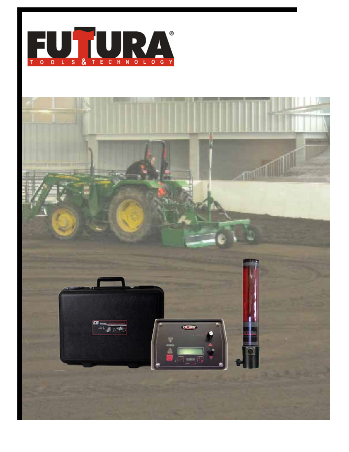
System Description
The EconoGrade Machine Control System was designed to let you achieve maximum control of your
grading system, at a very friendly price. The EG Series system is versatile, and can be installed on a
number of machines including box blades, box scrapers, graders, mini-graders and skid steers. The
system controls any valve package, giving the user both LED and a real-time LCD display so you are
always in touch with the blade position. The EconoGrade receiver can detect any rotating red beam
laser within its 173mm (7”) capture range, and in turn indicates the blade’s position to within a 2mm
(5/64”) accuracy. The receiver has LED indicator lights that give the same output as the control box
LED indicators. So whether you’re standing on the eld, or driving the machine you’ll always know
where your blade needs to be. The control box allows the user to congure the display to indicated
variances from the on grade position in real time. The receiver is able to attach to a 45mm (1 3/4”)
standard pipe. The complete system requires 9 - 30vdc to operate. The valve output drive is rated for
5 amps.
Page 1
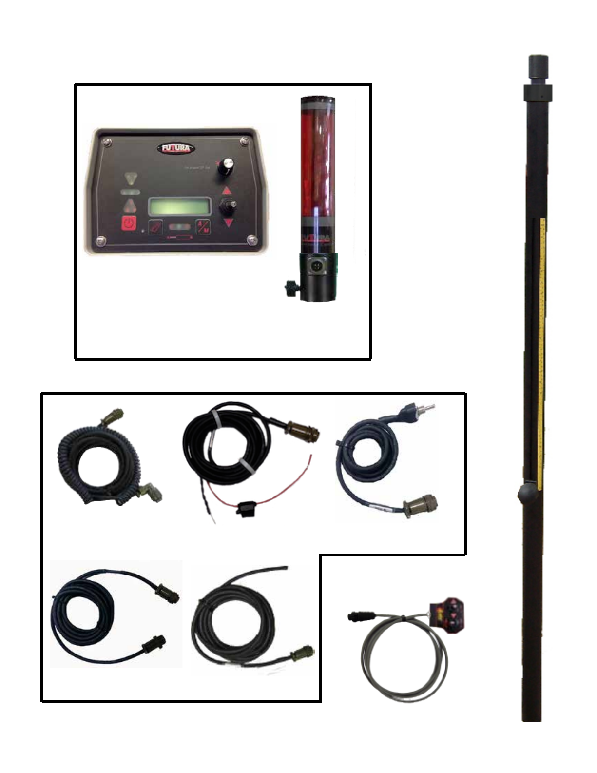
Control System
Control Box
System Components
Receiver
Optional
Telescoping Mechanical
Mast
Receiver Cable
Cable Set
18’ Power Cable
5’ Remote Switch
Optional 5’ Remote
Switch Cable
Receiver Adapter Cable
18’ Valve Cable
Page 2
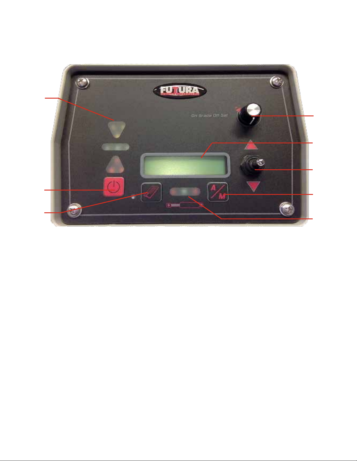
1.
2.
EG Series Control Box
Controls
(g 1)
8
7
6
5
3.
4
1) LED Grade Display - These LED’s display whether you are above grade, below grade or on
grade. The full 3 red or yellow LED arrows tell the user which direction the blade must move to
achieve on grade, while the single up or down LED will ash when the receiver is within 10mm
(0.39”) of the desired on grade. The green LED’s in the middle will ash when you are within your
desired ‘on grade’.
2) Power On/Off switch - Press the power button briey to turn it on, and the button must be pushed
and held for approximately two seconds to turn the system off.
3) Menu Button - This button is used to cycle through the menu system, and will only cycle through
in one direction. If you miss the screen you’re looking for the rst time through, you have to keep cy-
cling until you get to the home screen, then start again.
4) Hydraulic Indicator LED’s - These LED’s give the operator information on which valve is currently
being driven. The left LED shows valve one, the right shows valve two. The green LED shows all
valves are off
5) Auto/Manual button - This button switches the EG1 system between automatic and manual
mode when the slope display is showing. This button also gains special functions with respect to
some of the display screens shown below.
6) Valve Raise/Lower Switch - This toggle switch manually raises and lowers the hydraulics on your
machine. The toggle also acts as a switch when in the menu and can be used to change any parameter that appears in the display.
Page 3
7) LCD Display - This LCD displays system Information for the operator, like real time receiver
ongrade offset and auto / manual control settings. This display is also used for menu settings while
conguring the system at installation.
8. On-grade Offset - Controls the offset of the receiver’s on-grade. If you wanted to adjust the on-
grade setting by 54mm, you would do it with this control knob.
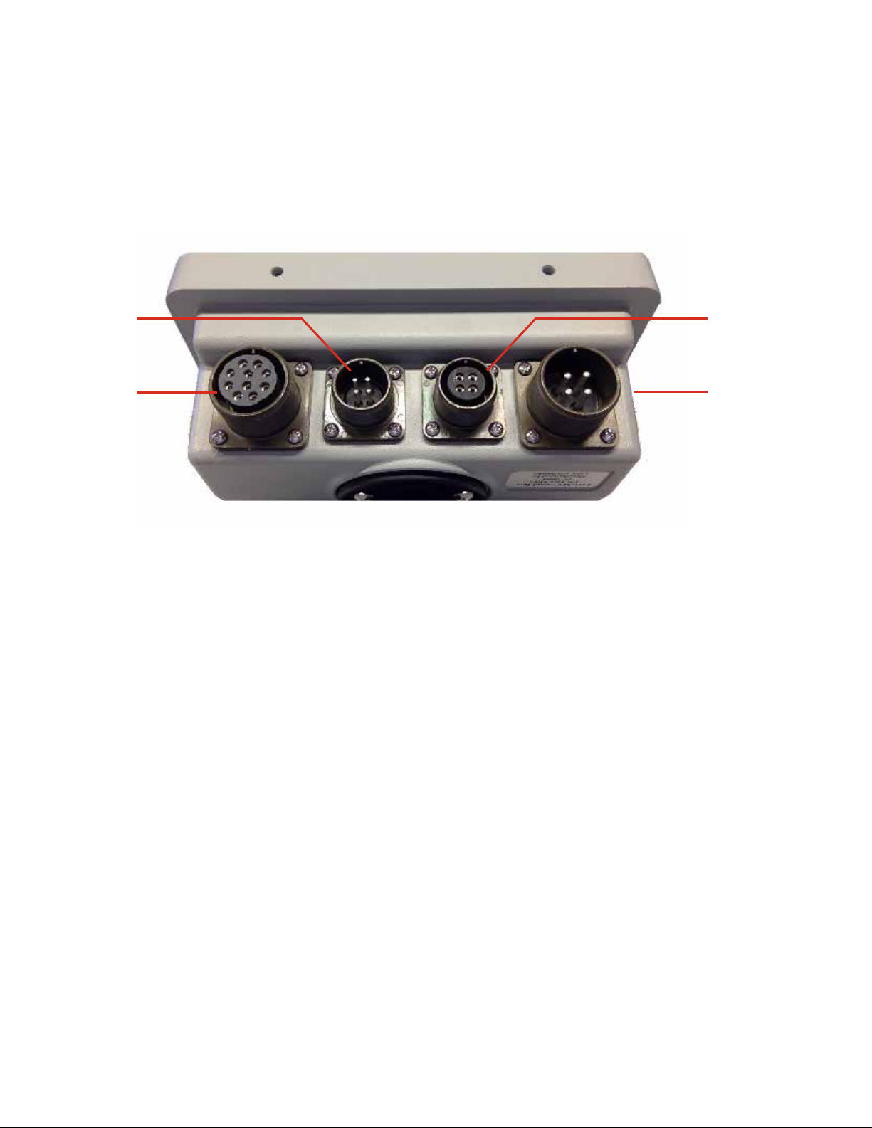
2
1
1 - Valve Cable Connector - This is where the valve is connected to the control box.
2 - Remote Switch Connector - Optional. The remote auto/raise/lower toggle switch
assembly plugs into the control box via this connector.
It allows you to manualy control the hydraulic cylinder as
well as the auto/manual functionality from a remote
location.
3
4
3 - Communication Connector - Receiver and other possible external devices plug into the
control box via this port, their signals are transferred to the
control box via this 4 pin connector.
4 - Power Cable Connector - This is where the battery power is connected to the
control box.
Page 4
EG Control
Ver 8 18 Oct 2016
Main Control Screen
31mm 3mm
Menu Manual
EG Series Control Box
Display Screens and Menus
Splash Screen -The EG Series has many menu screens for
setting up the system parameters. The rst to show up after
power on is the splash screen displaying system type and
version. The version and version date may change as features
and program modications are implemented.
The Main Control Screens: This is the rst screen displayed
after the 10 second start up routine is complete. The value
on the top left of the working screen is the actual value being
received by the receiver. The value on the top right side of the
working screen is the offset entered by the user.
---- 3mm
Menu Manual
Laser Recver Bad
Menu Manual
Operator Menu
Pass |EFFF| 0000
--> Return
The “No Beam Detected”- This image displays what the working screen will look like when the receiver loses the signal hit
from the laser during operation. The user entered offset is still
shown on the top right of the screen, however the actual ongrade value is replaced on the screen by dashes.
The “Laser Receiver Bad”- EG Series has self diagnostics to
keep your system working at peak performance, if a problem
occurs the main screen will display a message for the operator.
This is the screen you will see if there is no receiver connected
to the system, or if the control box can’t communicate with the
receiver. This may indicate a disconnected receiver or problem
with the cables
Operator menu - Entered by pressing the menu button.
System Lockout Screen - When entering the menu screens,
the system lockout screen will appear. You must enter the
system password to be able to go any further into the menu
screens. If this option is not needed it may be disabled in the
installation menu.
FAST -I- - - - Slow
Filtering Next
Valve deadband
0.5% grade Next
Page 5
Filtering: The ltering rate is a mathematical averaging lter
that can help to cure any jumpy behavior of the receiver. The
best setting is one place to the right of Fast for most applications
On-Grade Dead band - Is the amount of allowable on-grade
tolerance. The range is 1mm to 30mm at 1mm steps. When the
receiver is receiving the laser light in the on-grade position, the
valves will not activate until the dead band range is passed. If
the on-grade dead band is set to 10mm, the valves will not be
activated (Hydraulic Valve On) until the receiver readings are
beyond 5mm in either direction.

Horn Off
Next
Knob Adj Disabled
Change Next
Use Inches
Change Next
Horn - Sets the function of the internal beeper (Off, Alert,
Indicate). The Alert function has not been implemented at
this time. Setting the Indicate mode will sound a detector style
indication to the receiver position to on-grade. A double beep
when too high, a single beep when too low and a solid beep
when on grade while the system is in Automatic. Most operators leave this setting to Off.
Knob Adjust - Sets the function of the rotary knob from disabled (no function) to On Grade or VlvGain. When set to On
Grade the knob will adjust the on grade position on the receiver
up or down. If set to VlvGain, the knob will adjust the valve
gain hydraulic setting. This gives the operator the ability to
adjust the aggressiveness of the hydraulic system on the y.
Units - Set the system’s units to Millimeter, Inches or Feet
LATEC Instr. Inc
5192354585 Next
Installer Menu
Valve type
Prop time Next
Latec Info Screen - The nal screen in the Operators Menu
displays Latec Info, Name and phone number. Outside of North
America, dial +01.519.235.4585.
Note:
To access the Installation Menu , press the Menu
and Auto/Manual buttons in UNISON while the
LATEC info screen is displayed.
Installation Menu Enter Screen - The Installation menu area
is for experienced installers, here is where the crucial system
settings are adjusted and set. Some settings are intended to
move hydraulic systems for setup reasons, Caution Must Be
Observed. If you got here by accident, pressing the Power
Button will exit this menu at any time.
Page 6
 Loading...