

Page 1
2
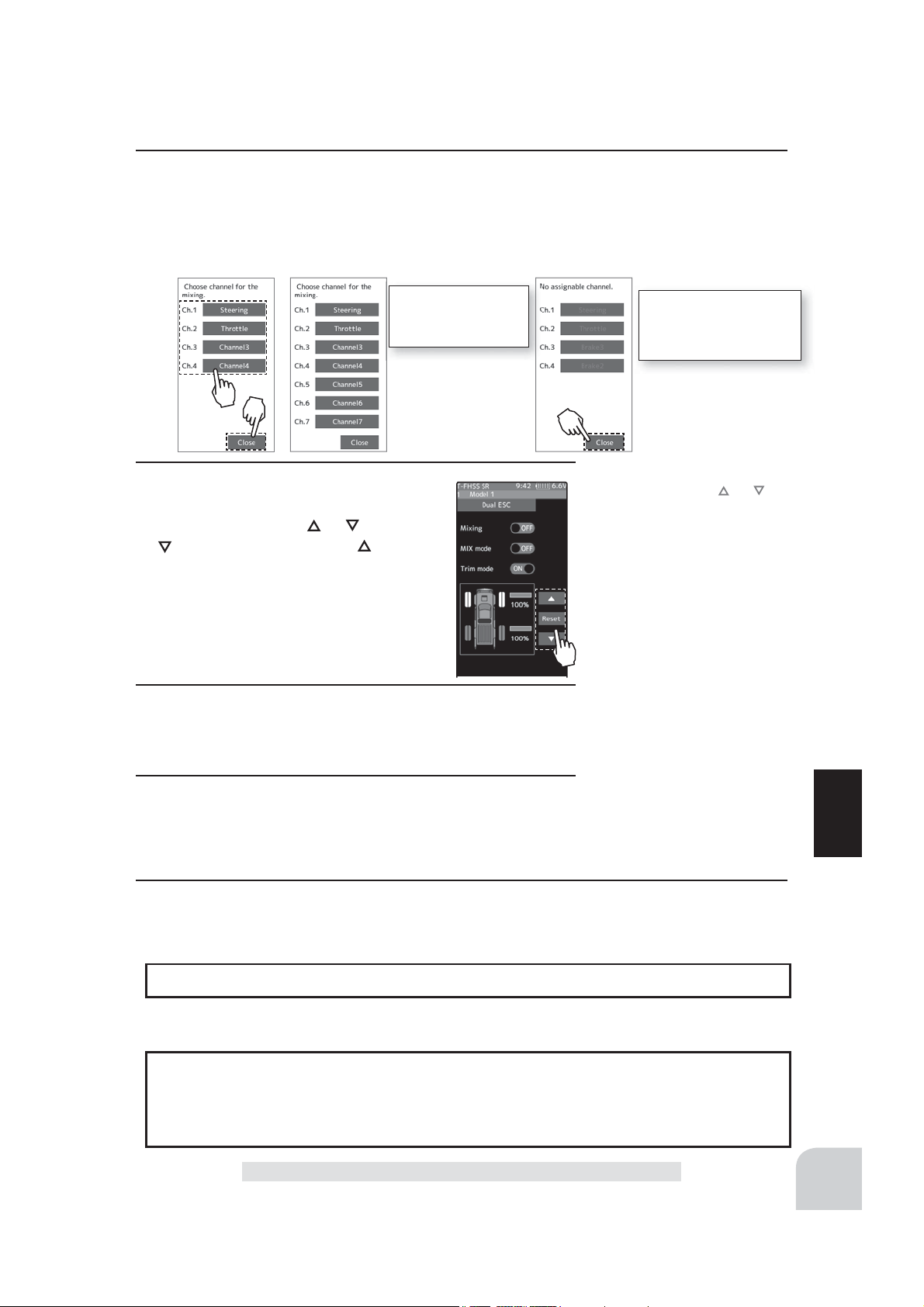
(Channel setup)
The channel list screen used for the front ESC channel is displayed. Tap the auxiliary channel that connected the front ESC channel.
- When all channels are in use, a screen saying "No assignable channel" is displayed, please turn off other mixing
and make an unused channel. You can check the mixing used on the channel setting screen (page 75).
For S-FHSS (analog)
system, 1 to 7 channels are displayed.
3
(Drive ratio adjustment)
Adjust the front and rear motor controller
operation amount by
button increases and the button de-
creases the rear ratio.
Both the front and rear ratios become
100%
4
(Mix mode setting)
Tap "MIX mode" (ON) or (OFF) to select ON / OFF.
"OFF" :The EXP function of the 2nd CH and other settings are not mixed.
"ON" :The EXP function of the 2nd CH and other settings are mixed.
5
(Trim mode setup)
Tap "Trim mode" (ON) or (OFF) to select ON / OFF.
"OFF" :The trim of the 2nd CH is not mixed.
"ON" :The trim of the 2nd CH is mixed.
or button. The
If there is no assignable
channel, tap [Close]. Turn
off other mixing and make
assignable channels.
Adjustment buttons
- Adjust with the and buttons.
- Return to the initial value by
tapping the [reset] buttons.
Rear rate (Rear mix rate)
0~100
Initial value:100
Setting
- Tap (ON) / (OFF).
Setting
- Tap (ON) / (OFF).
Function
6
When fi nished, return to the Mixing menu screen by pressing the HOME button twice.
Dial / Trim Setting
The dial select function can control the drive ratio with digital dial or digital trim.(page 66)
Note:
As this function drives 2 separate motor controllers simultaneously, a mutual load is applied. Use this function carefully so that the motor controllers are not damaged.
Futaba will not be responsible for motor controller, motor, and other vehicle trouble due
to use of this function.
Dual ESC
117
Page 2
CPS Mixing (1, 2, 3 )
This function controls the Futaba CPS-1 channel power switch. Normally, when using the
CPS-1 unit to light the vehicle dress-up and other illumination (LED) the CPS-1 unit with
LED connected is connected to a vacant switch channel and the LEDs are turned on and off
by switch while the vehicle is running. However, when the CPS mixing function is used, the
LED can be turned on and off and À ashed in step with steering and throttle operation, as
well as being turned on and off by switch. The À ashing speed (cycle) can also be set. For in-
stance, the LED can be À ashed as a brake light by throttle brake side operation. Three lines
of CPS mixing can be used.
The CPS-1 unit does not operate in SR mode. When using with the T - FHSS SR system, connect it to the channel of the normal mode.
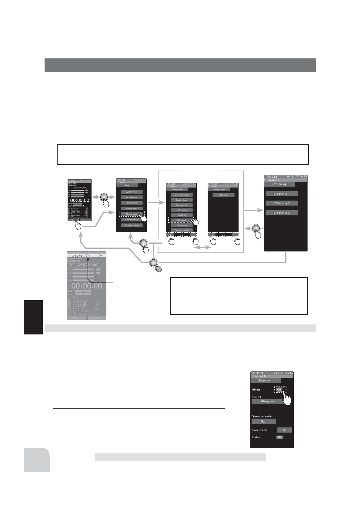
Home screen
Menu screen
Menu-1
The mixing function is assigned to auxiliary
channels used by other mixing cannot be used.
Display the current
drive mode.
Dual ESC mixing adjustment
Function
(Preparation)
- CPS-1 connects to the receivers auxiliary channel.
- When the LEDs are turned on and off by switch, use the function select switch function (page 69) to set the switch to be
used.
- From the CPS Mixing screen, tap [CPS Mixing 1] / [CPS Mixing 2] or [CPS Mixing 3] to display the setting screen.
When the number of channels is insuf¿ cient,
cancel the other mixing.
Mixing menu
CPS mixing
Menu-2
Setting
- Tap (ON) / (OFF).
118
1
(Function ON/OFF)
Tap "Mixing" (ON) or (OFF) to select ON / OFF.
"OFF" :Mixing function OFF
"ON" :Mixing function ON
CPS Mixing (1, 2, 3 )
Page 3
2
(Channel setup)
The channel list screen used for the front ESC channel is displayed. Tap the auxiliary channel that connected the front ESC channel.
- When all channels are in use, a screen saying "No assignable channel" is displayed, please turn off other mixing
and make an unused channel. You can check the mixing used on the channel setting screen (page 75).
3
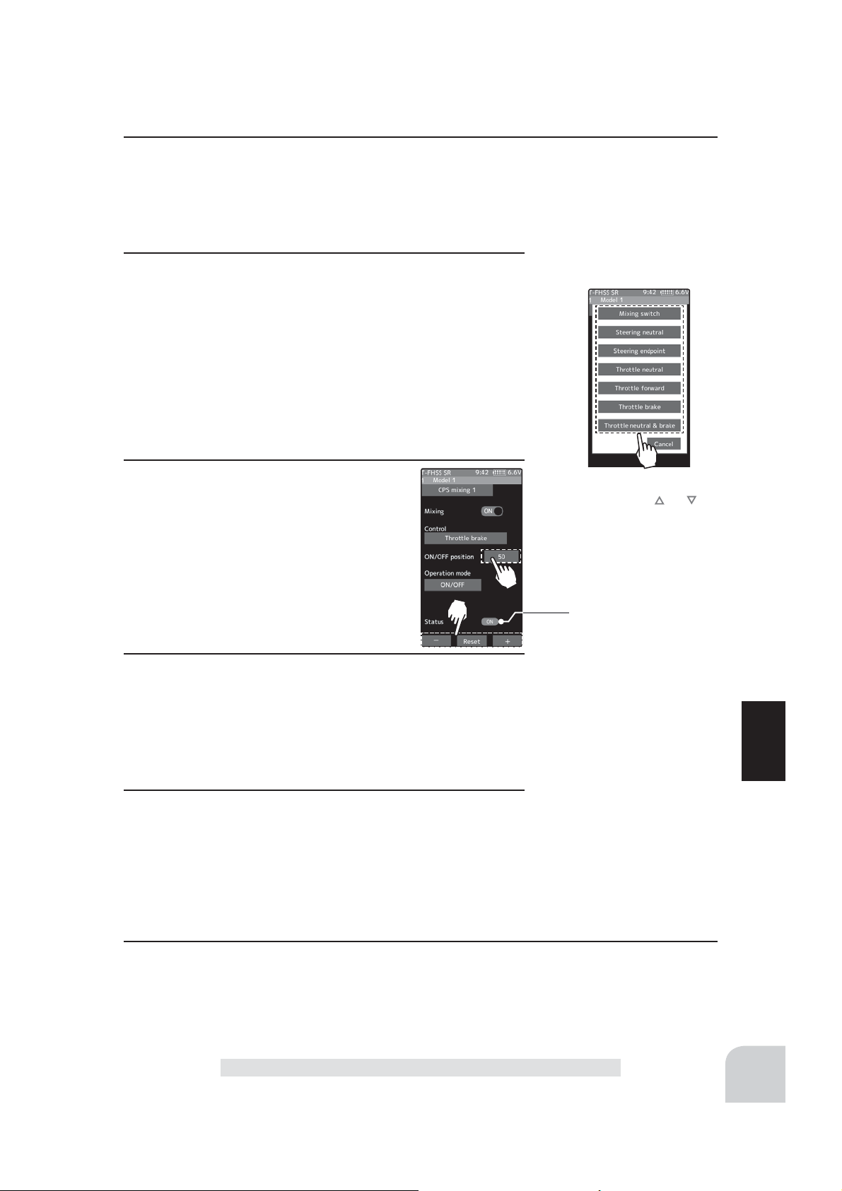
(Control system setup)
Tap the [Control]. The mode list appears on the CP-1 mixing menu screen, and tap from the list and select the control
mode. To cancel, tap [Cancel].
"Mixing Switch" : ON/OFF by switch set at the CPS mixing
"Steering neutral" : ON at steering neutral
"Steering endpoint" : ON at both sides of steering
"Throttle neutral" : ON at throttle neutral
"Throttle forward" : ON at throttle forward side
"Throttle brake" : ON at throttle back (brake) side
"Throttle neutral & brake" : ON at throttle neutral and back (brake) sides
4
(ON / OFF switching position selection)
Tap the value button of the [ON/OFF point].
Value input buttons appear on the screen.
Use the [+] and [-] buttons to adjust the
operation point. Since the ON/OFF state is
displayed at the right side of the "Status",
setting can be confirmed while operating
the function to be controlled (for example,
throttle).
5
(Operation mode setup)
Tap the [Operation mode]. The mode list appears on the
CP-1 mixing menu screen, and tap from the list and select
the Operation mode. To cancel, tap [Cancel].
"ON/OFF" : Normal ON/OFF type
"Flash" : Flashing display
6
(Flashing cycle setting)
When "Operation mode" is set to "Flash" the "Cycle speed"
can be set to preferred setting. Tap the value button of the
[Cycle speed]. Value input buttons appear on the screen. Use
the [+] and [-] buttons to adjust the cycle speed amount.
Setting
- Tap control mode.
Adjustment buttons
- Adjust with the and buttons.
- Return to the initial value by
tapping the [reset] buttons.
ON/OFF position
5 ~ 95
Initial value:50
*Shows the ON/OFF state
Setting
- Tap operation mode.
Adjustment buttons
- Adjust with the [+] and [-] buttons.
- Return to the initial value by
tapping the [reset] buttons.
Cycle speed amount
1~100
Initial value: 50
Function
7
When finished, return to the Mixing menu screen by pressing the HOME button twice.
CPS Mixing (1, 2, 3 )
119
Page 4
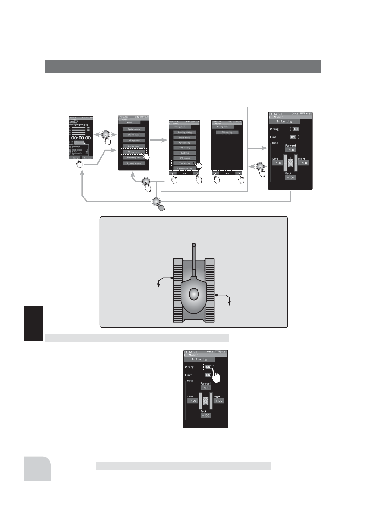
Tank Mixing
This function is intended for vehicles such as tanks and can be used to the pivotal turn, or
the ultra-pivotal brake turn, by steering and throttle operation.
Home screen
Menu screen
The channels connecting the left and right motor control-
lers are as shown in the figure.
Menu-1
Connection channel
Menu-2
Tank mixing
120
Tank mixing adjustment
Function
1
(Function ON/OFF)
Tap "Mixing" (ON) or (OFF) to select ON /
OFF.
"OFF" :Mixing function OFF
"ON" :Mixing function ON
Throttle channel
Steering channel
Setting
- Tap (ON) / (OFF).
Tank Mixing
Page 5
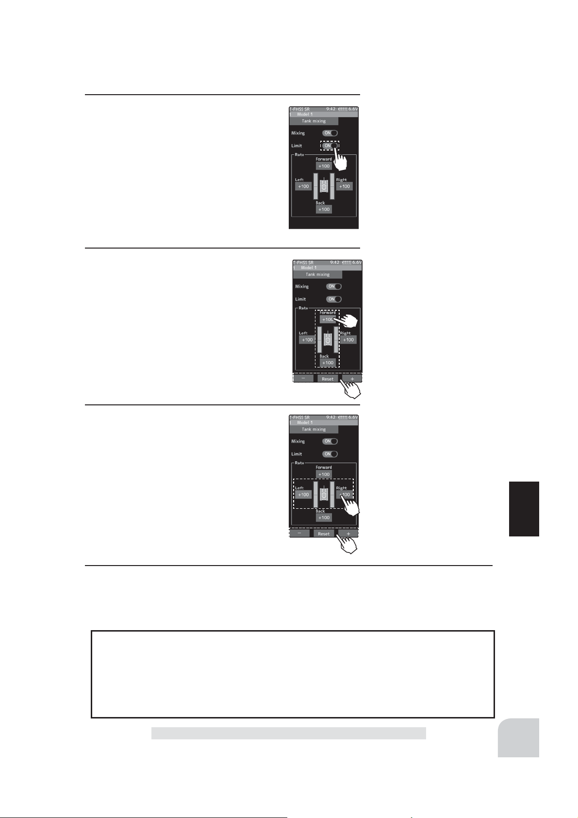
2
(Limit ON / OFF)
It is a function to limit the maximum operation amount of the steering and throttle
channel so that it does not exceed the limit
by the influence of the mixing amount.
Tap "Limit" (ON) or (OFF) to select ON /
OFF.
“OFF” :Limit function OFF
“ON” :Limit function ON
3
(Forward / backward rate adjustment)
Tap the value button of the [Forward] or
[Bsck]. Value input buttons appear on the
screen. Use the [+] and [-] buttons to adjust
the forward or reverse speed.
- The throttle channel and the steering channel operate
in conjunction with each other, and by operating the
trigger to the high side, the car body advances at the
[Forward] rate. When the trigger is operated to the
brake side, it operates at the [Bsck] rate.
Setting
- Tap (ON) / (OFF).
.
Adjustment buttons
- Adjust with the [+] and [-] buttons.
- Return to the initial value by
tapping the [reset] buttons.
Forward / backward rate
-100~+100
Initial value: +100
4
(Left / Right side travel adjust)
Tap the value button of the [Left] or [Right].
Value input buttons appear on the screen.
Use the [+] and [-] buttons to adjust the left
Adjustment buttons
- Adjust with the [+] and [-] buttons.
- Return to the initial value by
tapping the [reset] buttons.
or right side travel amount.
- When the throttle channel and the steering channel
work in conjunction, when operating the steering
wheel to the right, the car body turns to the right at
the [Right] rate the pivotal turn. If you operate to the
left, the car will turn to the left at the [Left] rate the
pivotal turn.
5
When finished, return to the Mixing menu screen by pressing the HOME button twice.
Left / Right travel
-100~+100
Initial value: +100
When steering and trigger are operated at the same time.
If you manipulate the trigger to the high side and operate the steering wheel to the right,
the body will turn right at the rate of [forward], [right].
If you manipulate the trigger to the high side and operate the steering wheel to the left,
the body turns to the left at the rate of [forward], [left].
Operating the steering wheel while operating the trigger to the brake side will operate
the same as the forward side in the reverse direction.
Function
Tank Mixing
121
Page 6
Program, Mixing (1, 2, 3, 4, 5 )
These functions allow you to apply mixing between the steering, throttle and auxiliary
channel.
Additional Functions
-When the steering or throttle channel is the master channel (channel that applies mixing), trim data can be added. (Trim mode)
- The mixing mode selection. (Master mixing mode)
- The master channel mixing center point (point at which the direction changes) can be
offset. (Offset function)
Movement of the slave channel side
The movement of the master channel side will be added to the movement of the slave
channel side.
When trigger ratio was set to 100:0
When trigger ratio (page 62) is set to 100:0, brake operation stops. When the master
channel is set to throttle, mixing operates only at the "Rate A (forward)" side. It does not
operate at the "Rate B (brake)" side.
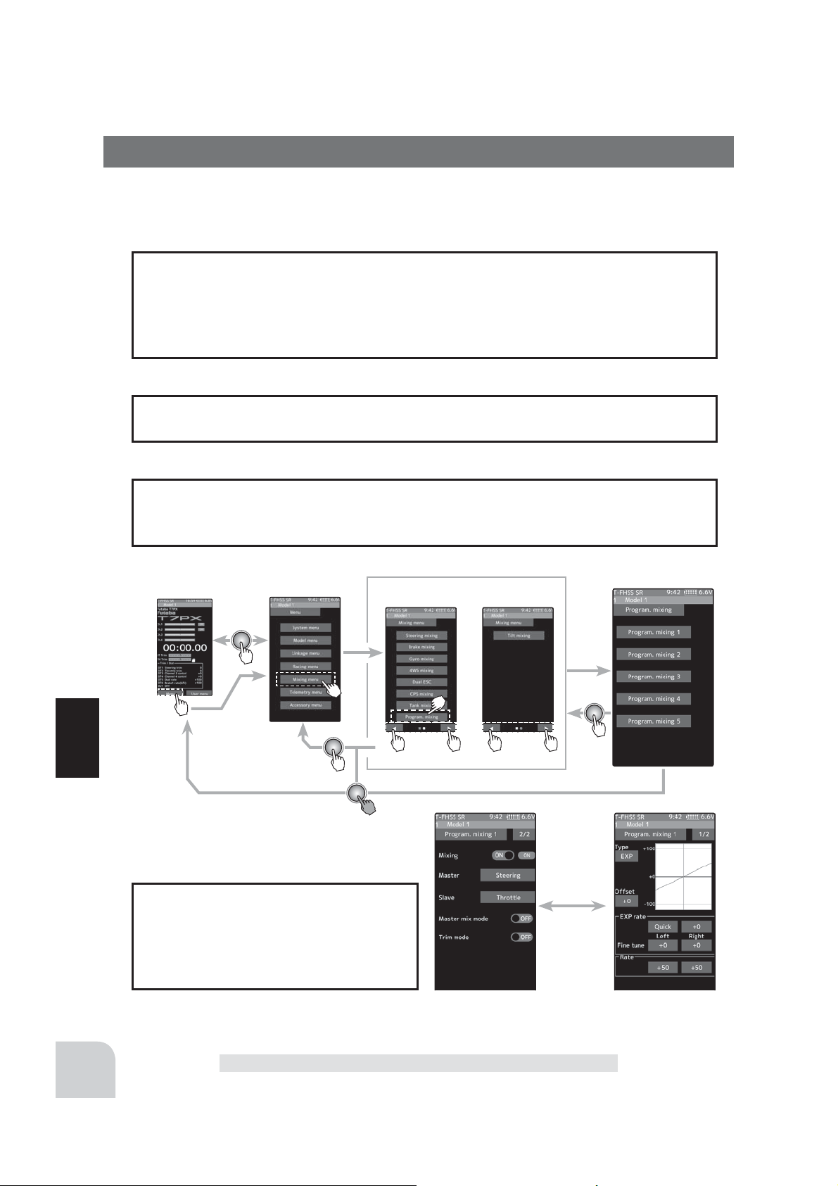
Home screen
Menu screen
Menu-1
Menu-2
Program. mixing
Function
The mixing function is assigned to auxiliary channels used by other mixing
cannot be used. When the number of
channels is insuf¿cient, cancel the other
mixing.
122
On the page 1, the setting screen such as the curve, mix-
ing rate adjustment screen, page 2, mixing ON / OFF etc.
is displayed.
Program, Mixing (1, 2, 3, 4, 5)
Page 7

Program composite adjustment
(Preparation)
- Use the switch select function (page 69) to select the switch. (as
desired)
- From the Program Mixing screen Tap [Program Mixing 1] [Program Mixing 5] to use to move to the setting screen.
1
(Function ON/OFF)
Tap [1/2] at the upper right of the screen to display page 2.
Tap "Mixing" (ON) or (OFF) to select ON / OFF.
"OFF" :Mixing function OFF
"ON" :Mixing function ON
2
(Master / Slave channel setup)
Tap the [Master] or [Slave], and the channel setting screen
will be displayed. Tap on that channel to select.
To cancel, tap [Close].
Setting
- Tap (ON) / (OFF).
Setting
- Tap channel.
3
(Mix mode setting)
Tap "MIX mode" (ON) or (OFF) to select ON / OFF.
“OFF” :The EXP function of the 2nd CH and other settings are not mixed.
“ON” :The EXP function of the 2nd CH and other settings are mixed.
4
(Trim mode setup)
Tap "Trim mode" (ON) or (OFF) to select ON / OFF.
"OFF" :The trim of the 2nd CH is not mixed.
"ON" :The trim of the 2nd CH is mixed.
Program, Mixing (1, 2, 3, 4, 5)
For S-FHSS (analog)
system, 1 to 7 channels are displayed.
Setting
- Tap (ON) / (OFF).
Function
123
Page 8
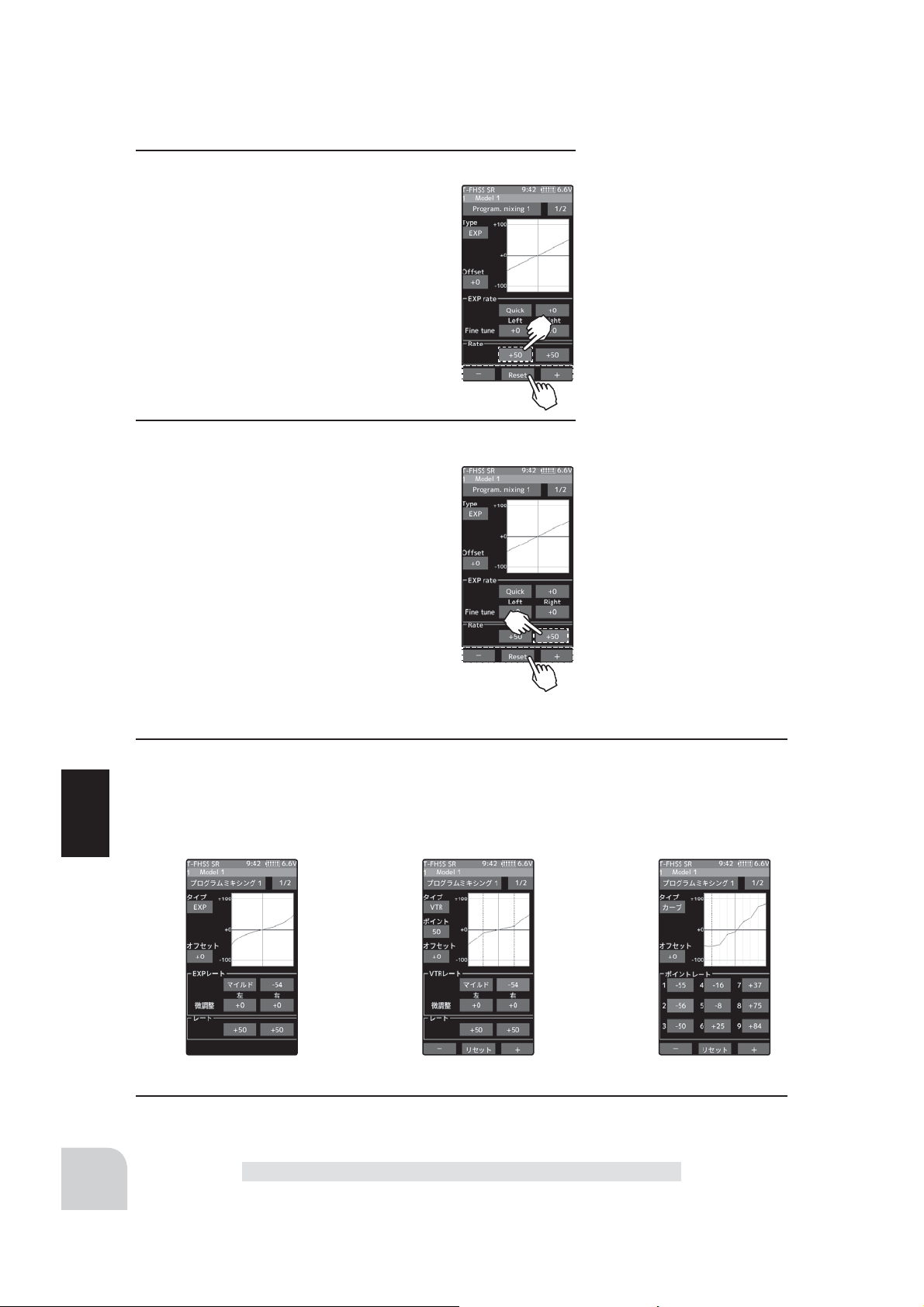
5
(Left, Forward or A side mixing amount adjustment)
Tap the value button of the "Rate" [Left],
[Forward] or [Rate A] . Value input buttons
appear on the screen, adjust each of the
left, forward or A steering angles using the
[+] or [-] button.
6
(Right, brake or B side mixing amount adjustment)
Tap the value button of the "Rate" [Right],
[Brake] or [Rate B] . Value input buttons
appear on the screen, adjust each of the
right, brake, or rate B steering angles using
the [+] or [-] button.
Adjustment buttons
- Adjust with the [+] and [-] buttons.
- Return to the initial value by
tapping the [reset] buttons.
Left / Forward / A side rate
-120~0 ~+120
Initial value: +50
Adjustment buttons
- Adjust with the [+] and [-] buttons.
- Return to the initial value by
tapping the [reset] buttons.
Right / Blake / B side rate
-120~0 ~+120
Initial value: +50
124
7
(Curve setting)
"EXP / VTR / Curve" mixing can be set from master channel to slave channel. For details on
how to set each curve, please read the steering curve and the throttle curve (pages 78 to
83).
Function
EXP curve VTR curve Curve
8
When finished, return to the Mixing menu screen by pressing the HOME button twice.
Program, Mixing (1, 2, 3, 4, 5)
Page 9
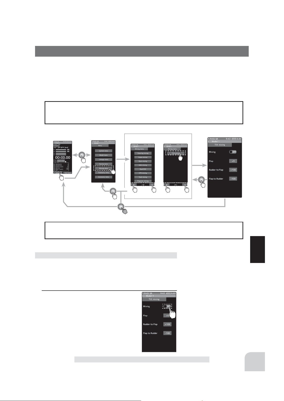
Tilt Mixing
Tilt mixing uses an outboard engine and applies bidirectional mixing from rudder to steady
to Àap and from Àap to rudder so that with a boat, rudder operation and tilt mixing opera
tion can be performed 2 servos.
Tilt mixing can be performed by rudder operation, by steering wheel and Àap channel.
Effect of the set value of other functions on tilt mixing
Steering end point function, curve function, speed function, or D/R function setup also
effects Àap channel operation. However, even if set, steering reverse function setup does
not reverse the Àap channel.
-
Home screen
Menu screen
Menu-1
Menu-2
mixing
The mixing function is assigned to auxiliary channels used by other mixing cannot be
used. When the number of channels is insuf¿cient, cancel the other mixing.
Program composite adjustment
(Preparation)
- Use the "Trim/dial select" function to select the flap channel
operation dial. (page 662)
Function
1
(Function ON/OFF)
Tap [1/2] at the upper right of the screen to
display page 2.
Tap "Mixing" (ON) or (OFF) to select ON /
OFF.
"OFF" :Mixing function OFF
"ON" :Mixing function ON
Tilt Mixing
Setting
- Tap (ON) / (OFF).
125
Page 10
2
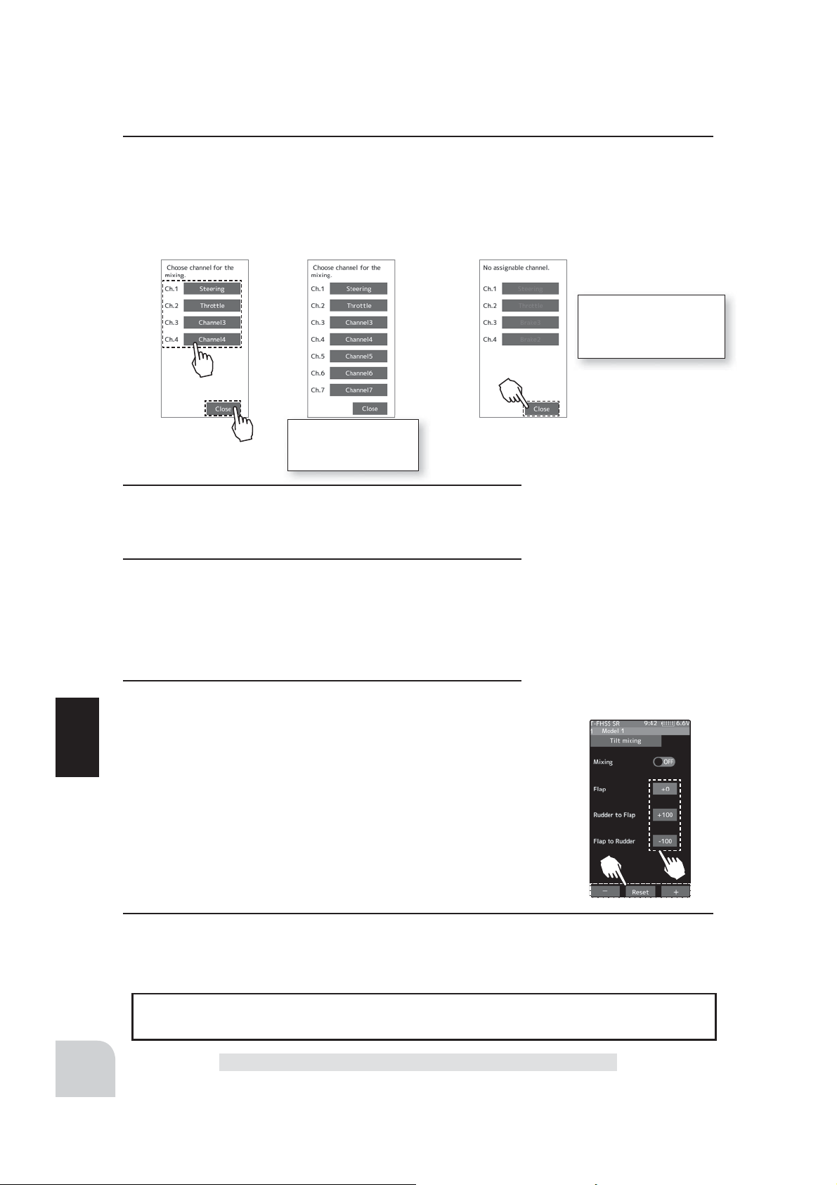
(Channel setup)
The channel list screen used for the gain steering channel is displayed. Tap the auxiliary
channel that connected the gain steering channel.
- When all channels are in use, a screen saying "No assignable channel" is displayed, please turn off other mixing
and make an unused channel. You can check the mixing used on the channel setting screen (page 75).
If there is no assignable
channel, tap [Close]. Turn
off other mixing and make
assignable channels.
For S-FHSS (analog)
system, 1 to 7 channels are displayed.
3
(Flap rate check and adjustment)
Select the "Flap" by (JOG) button up or down operation, and
adjust the fl aps by [+] or [-] operation.
4
(Rudder to Flap mixing amount adjustment)
Tap the value button of the "Rudder to Flap", Value input buttons appear on the screen, and use the [+] and [-] buttons to
adjust the mixing amount.
“+” :Operate in same direction as steering
“-” :Operate in opposite direction of steering
5
(Flap to Rudder mixing amount adjustment)
Tap the value button of the "Flapto Rudder", Value input buttons appear on the screen, and use the [+] and [-] buttons to
adjust the mixing amount.
Function
“+” :Operate in same direction as auxiliary channel
“-” :Operate in opposite direction of auxiliary channel
Adjustment buttons
- Adjust with the [+] and [-] buttons.
- Return to the initial value by
tapping the [reset] buttons.
Mixing amount (Rudder to Flap)
-100~+0~+100
Initial value: +100
Mixing amount (Flap to Rudder)
-100~+0~+100
Initial value: -100
126
6
When fi nished, return to the Mixing menu screen by pressing the HOME button twice.
Dial / Trim Setting
The mixing rate amount can be controlled with digital dial or digital trim, using the dial
select function.(page 66)
Tilt Mixing
Page 11
Timer
Use the timer by selecting one of the four timers Up timer, Fuel down timer, Lap timer and
Lap navigate timer.
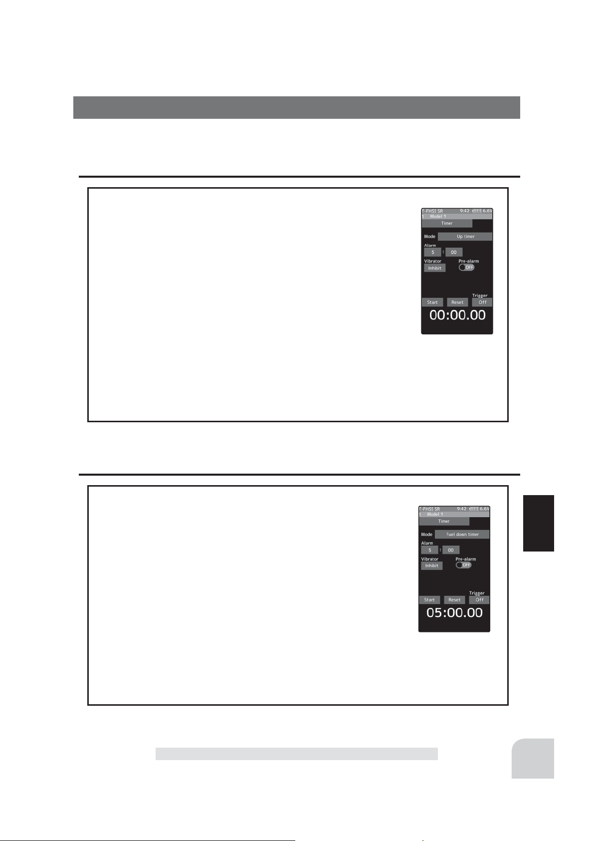
Up timer function
- The Up timer can be used to count the time between start and stop, etc.
- The timer repeatedly starts and stops each time the switch is operated and accumulates the time between each start and stop. (When
the count reaches 99 minutes 59 seconds, it returns to 00 minutes 00
seconds and repeats the count.)
- The ¿rst start operation can be linked to the throttle trigger.
- An alarm sound can be set. The passage of time is announced by
sounding of a buzzer (beeps) each minute after starting.
- Alarm :Generates a beep at the set time (minutes).
- Pre-alarm :Alarm advance announcement sound. Sounding begins 10 seconds before the set alarm time.
- After starting, the timer is enabled and can be stopped by switch even when the display
switches to another screen.
Fuel down timer function
- The Up timer can be used to count the time between start and stop, etc.
- The timer repeatedly starts and stops each time the switch is operated and accumulates the time between each start and stop. (When
the count reaches 99 minutes 59 seconds, it returns to 00 minutes 00
seconds and repeats the count.)
- The ¿rst start operation can be linked to the throttle trigger.
- An alarm sound can be set. The passage of time is announced by
sounding of a buzzer (beeps) each minute after starting.
- Alarm :Generates a beep at the set time (minutes).
- Pre-alarm :Alarm advance announcement sound. Sounding begins 10 seconds before the set alarm time.
- After starting, the timer is enabled and can be stopped by switch even when the display
switches to another screen.
Timer
Function
127
Page 12
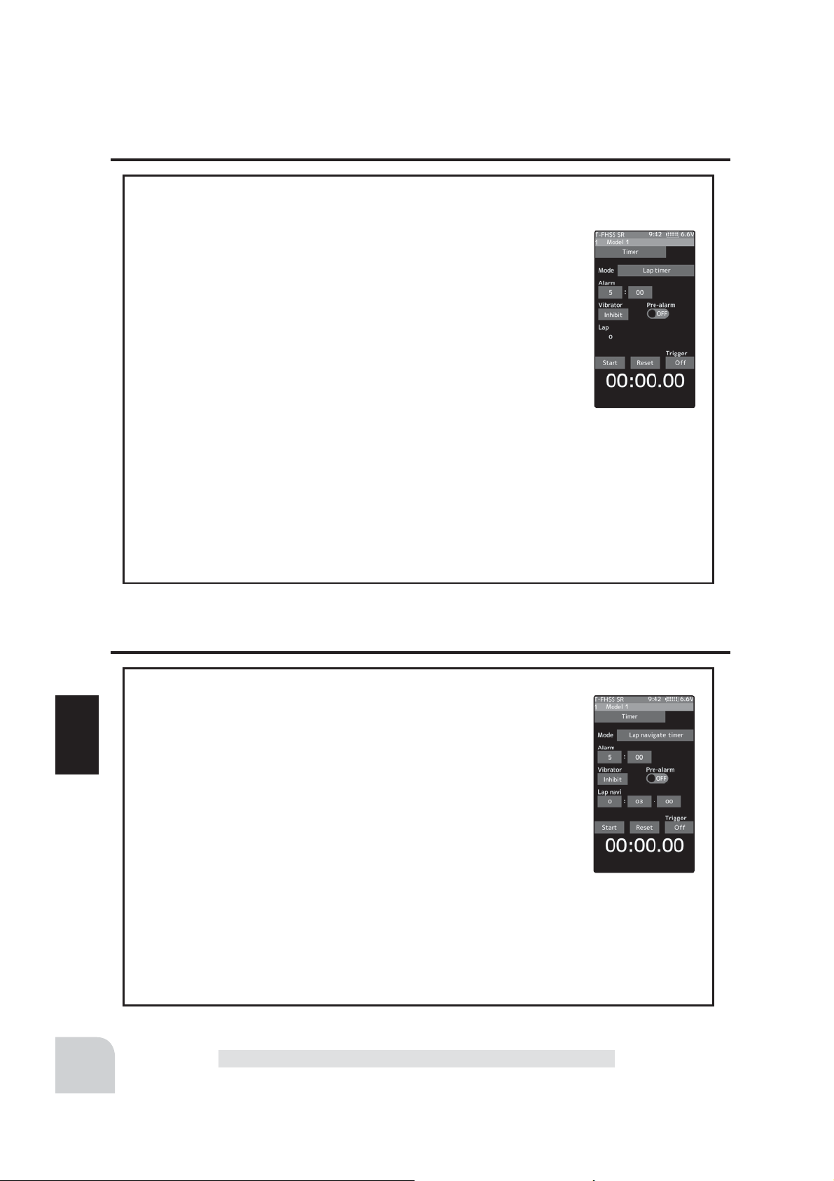
Lap timer function
Lap timer function
- The Lap timer can memorize each lap time of each switch operation. (80 laps)
- The race time can be set. Switch operation after the set time by
alarm has elapsed automatically stops the timer. Pre-alarm can also be
set. The passage of time is announced by sounding of a buzzer (beeps)
each minute after starting.
-Alarm :Generates a beep at the set time.
Pre-alarm :Starts sounding the set time (second) before the alarm. (beeps)
- The ¿rst start operation can be linked with the throttle trigger.
(Lap timer operation)
- When lap timer is selected, the number of laps (LAP) and the lap memory No. (No.) and
current lap time (TIME) are displayed on the setup screen.
* LAP: Counted up each time the switch is pressed after starting. After the switch was pressed, the numbers
pause for 3 seconds. To prevent erroneous counting, switch operation is not accepted during this time
* Lap memory: The lamp memory saves the lap times of 80 laps.
* The lap time data stored in the lap memory can be checked at the lap list (page 134) screen.
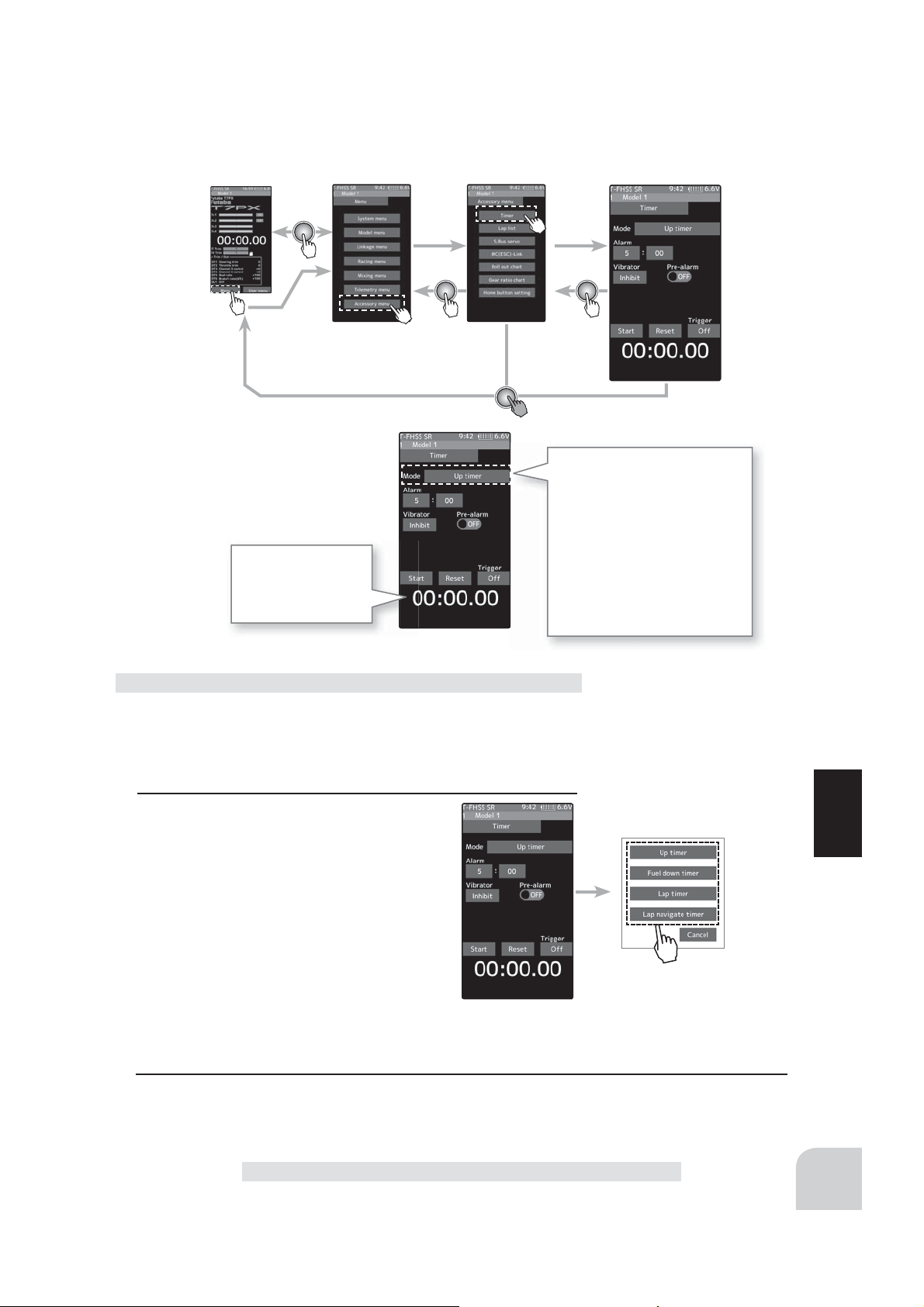
Lap navigate timer function
Lap navigate timer function
- This function sounds a buzzer at a fixed interval after the timer
starts. Since only the buzzer can be restarted when the switch is
pressed during timer operation, this function can be used as the train
ing run, etc. target time. (Lap navigation alarm) The passage of time
Function
is announced by sounding of a buzzer (beeps) every minute after
starting.
- The ¿rst start operation can be linked with the throttle trigger.
- The alarm sounds (alarm/Pre-alarm) can be set separately from the
¿xed interval buzzer.
- Alarm :Generates a beep at the set time (minutes).
- Pre-alarm :Alarm advance announcement sound. Sounding begins 10 seconds before the set alarm time.
- After starting, the timer is enabled and can be stopped by switch even when the display
switches to another screen.
-
128
Timer
Page 13
Home screen
Time display
Minute display (m)
Second display (s)
1/100 second display
Menu screen Accessory menu screen
Timer
Timer selection
First, select the type of timer
at the "Mode" item. The setup
screen varies depending on the
type of timer. This fi gure shows
the Up timer setup screen.
-Up timer
-Fuel down timer
-Lap timer
-Lap navigate timer
Racing timer type selection
(Preparation)
Assign the "Timer start" switch using the Switch select func-
Setting type
- Tap to select
tion (page 69). When resetting by switch, assign "Timer reset"
also.
1
(Racing timer type selection)
Tap the "Mode". The mode list appears on
the "Timer" menu screen, and tap the racing timer type.
Up timer
Fuel down timer
Lap timer
Lap navigate timer
2
When fi nished, return to the Accessory menu screen by pressing the HOME button.
Function
Timer
129
Page 14
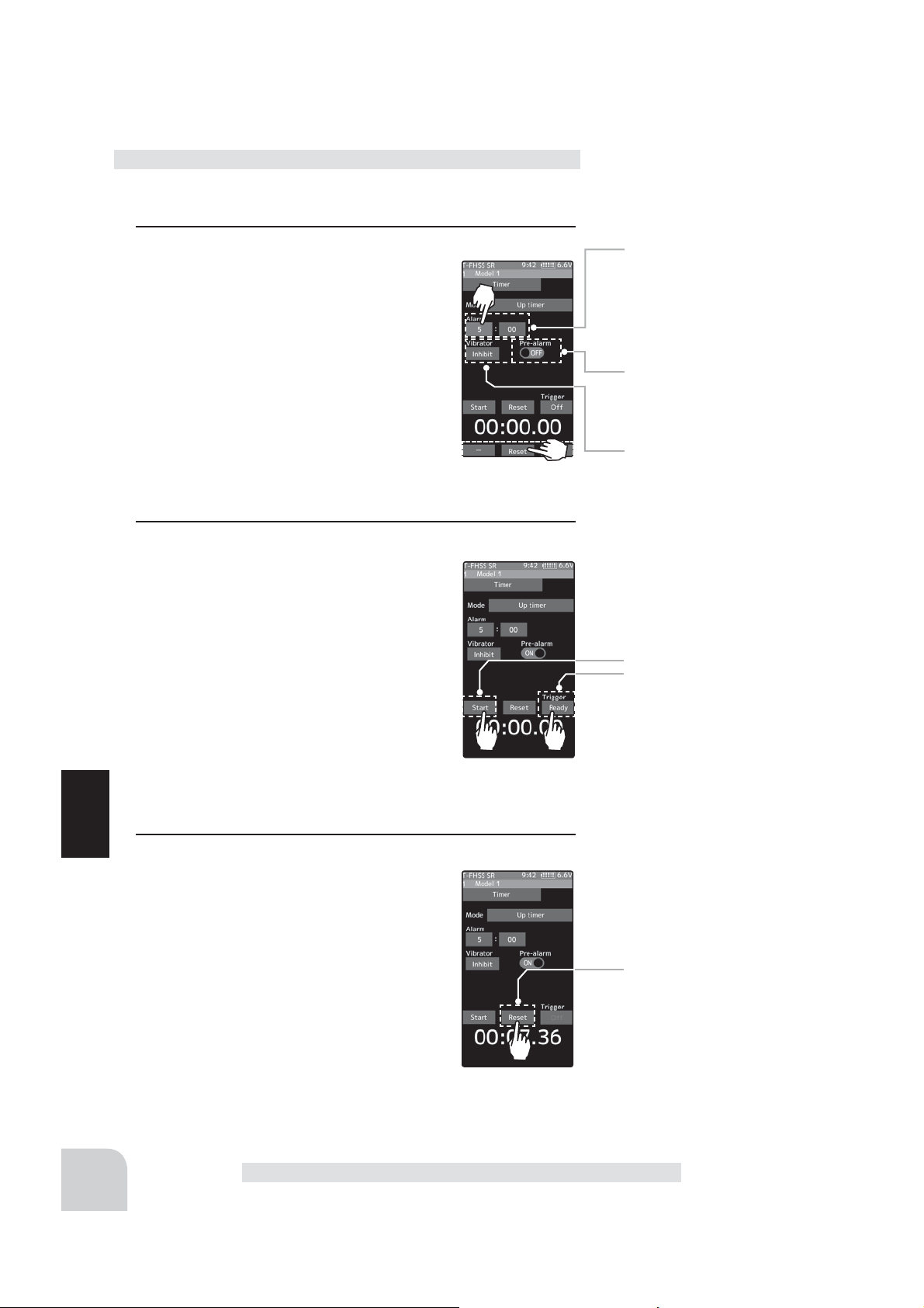
Using the Up timer
(Preparation)
Select the “Up timer” from the timer type list and tap.
1
(Alarm time setting)
Tap the value button of the "Alarm time".
Value input buttons appear on the screen.
use the [+] and [-] buttons to set the time
amount.
Tap [Vibrate] and select the vibration pattern of the alarm from 3 types of patterns
and disable (OFF).
(Pre-alarm setting)
Tap (ON) or (OFF) of pre-alarm and select
ON / OFF.
2
(Timer start/stop operation)
When the switch (Timer start) assigned by
switch select function is pressed, the timer
starts. When you press the switch (Timer
start) or [Start] / [Reset] on the screen during timer operation, the timer stops.
- Linking only start to the throttle trigger
Tap [OFF] of the trigger to display [Ready]
and wait for the trigger operation. When
you operate the trigger to the forward side,
the timer starts. Stop is the same as when starting with a
switch.
Alarm time
OFF, 1 ~ 99 minutes
Initial value: 5 minutes
- Adjust with the [+] and [-] buttons.
- Return to the initial value by
tapping the [reset] buttons.
Pre-alarm time
OFF, ON
Initial value: OFF
- Tap (ON) / (OFF).
Grip vibrator type (pattern)
Inhibit(Off), Type1,2,3
Initial value: Inhibit
- Tap (ON) / (OFF).
Start / Stop
Status display
130
3
Function
(Timer reset operation)
With the timer stopped, press the switch
(timer reset) set by the Switch setting function, or tap [Reset] on the screen. The
timer is reset with the beeping sound.
Timer reset
Brake Mixing
Page 15
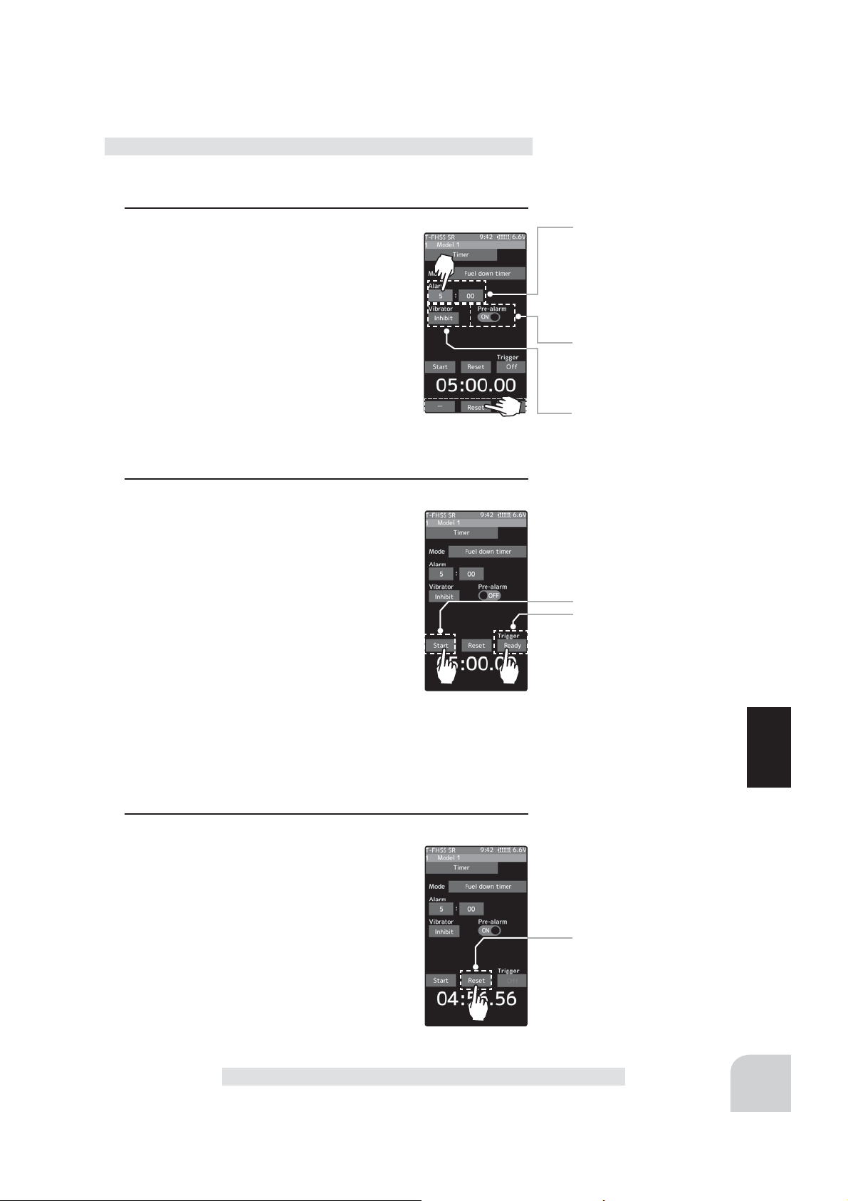
Using the fuel down timer
(Preparation)
Select the "Fuel down timer” from the timer type list and tap.
1
(Alarm time setting)
Tap the value button of the "Alarm time".
Value input buttons appear on the screen.
use the [+] and [-] buttons to set the time
amount.
Tap [Vibrate] and select the vibration pattern of the alarm from 3 types of patterns
and disable (OFF).
(Pre-alarm setting)
Tap (ON) or (OFF) of pre-alarm and select
ON / OFF.
2
(Timer start/stop operation)
When the switch (Timer start) assigned by
switch select function is pressed, the timer
starts.
When the switch ("Timer start") is pressed
while the timer is operating, the timer is reset and simultaneously restarted. (Restart)
When you press the [Reset] on the screen
during timer operation, the timer stops.
- Linking only start to the throttle trigger
Tap [OFF] of the trigger to display [Ready] and wait for the
trigger operation. When you operate the trigger to the forward
side, the timer starts. Stop is the same as when starting with
a switch.
Alarm time
OFF, 1 ~ 99 minutes
Initial value: 5 minutes
- Adjust with the [+] and [-] buttons.
- Return to the initial value by
tapping the [reset] buttons.
Pre-alarm time
OFF, ON
Initial value: OFF
- Tap (ON) / (OFF).
Grip vibrator type (pattern)
Inhibit(Off), Type1,2,3
Initial value: Inhibit
- Tap (ON) / (OFF).
Start / Stop
Status display
Function
3
(Timer reset operation)
With the timer stopped, press the switch
(timer reset) set by the Switch setting function, or tap [Reset] on the screen. The timer
is reset with the beeping sound.
Brake Mixing
Timer reset
131
Page 16
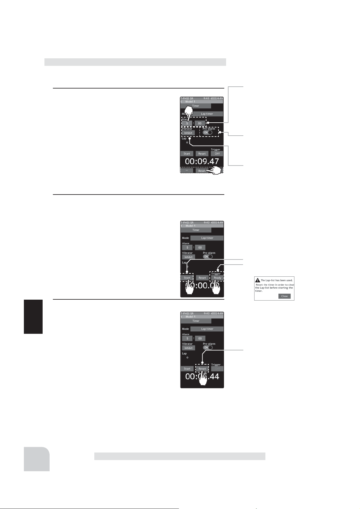
Using the lap timer
(Preparation)
Select the "Lap timer" from the timer type list and tap.
1
(Alarm time setting)
Tap the value button of the "Alarm time".
Value input buttons appear on the screen.
use the [+] and [-] buttons to set the time
amount.
Tap [Vibrate] and select the vibration pattern of the alarm from 3 types of patterns
and disable (OFF).
(Pre-alarm setting)
Tap (ON) or (OFF) of pre-alarm and select ON / OFF.
2
(Timer start operation)
Perform the start and lap count operations with the switch
("Timer start") assigned by function select
switch function.
- Linking only start to the throttle trigger
Tap [OFF] of the trigger to display [Ready]
and wait for the trigger operation. When
you operate the trigger to the forward side,
the timer starts. Stop is the same as when
starting with a switch.
Alarm time
OFF, 1 ~ 99 minutes
Initial value: 5 minutes
- Adjust with the [+] and [-] buttons.
- Return to the initial value by
tapping the [reset] buttons.
Pre-alarm time
OFF, ON
Initial value: OFF
- Tap (ON) / (OFF).
Grip vibrator type (pattern)
Inhibit(Off), Type1,2,3
Initial value: Inhibit
- Tap (ON) / (OFF).
Start / Stop
Status display
132
3
(Timer stop and lap reset operation)
When the lap count switch or ("Timer reset") switch is pressed after the time set by
Function
"Alarm" has elapsed and the lap time, total
time, and average lap time are saved and
checked. (Lap list page 134) If the switch
Timer reset
("Timer reset") set by switch setting function is pressed, the timer is reset.
When a switch is not set, tap [Reset] on the
screen. The timer is reset with the beeping
sound.
Brake Mixing
Page 17

Using the lap navigate timer
(Preparation)
Select the "Lap navigate timer" from the timer type list and tap.
1
(Alarm time setting)
Tap the value button of the "Alarm time".
Value input buttons appear on the screen.
use the [+] and [-] buttons to set the time
amount.
Tap [Vibrate] and select the vibration pattern of the alarm from 3 types of patterns
and disable (OFF).
(Pre-alarm setting)
Tap (ON) or (OFF) of pre-alarm and select
ON / OFF.
(Lap navigation time setting)
Tap the value button of the "Lap navi". Value input buttons
appear on the screen. use the [+] and [-] buttons to set the
time amount.
2
(Timer start / navigation restart operation)
When the switch ("Timer start") assigned
by switch select function is pressed, the
timer starts.
- Linking only start to the throttle trigger
Tap [OFF] of the trigger to display [Ready]
and wait for the trigger operation. When
you operate the trigger to the forward side,
the timer starts. Stop is the same as when
starting with a switch.
When your own lap time is less than the target time and the
lap counts overlap, the lap navigation alarm timing is too big.
The alarm timing can be corrected by pressing the switch
("Timer start") during measurement.
Alarm time
OFF, 1 ~ 99 minutes
Initial value: 5 minutes
- Adjust with the [+] and [-] buttons.
- Return to the initial value by
tapping the [reset] buttons.
Pre-alarm time
OFF, ON
Initial value: OFF
- Tap (ON) / (OFF).
Grip vibrator type (pattern)
Inhibit(Off), Type1,2,3
Initial value: Inhibit
- Tap (ON) / (OFF).
Navi alarm time (NAVI)
OFF, 1 ~ 99 seconds
Initial value: 3 seconds
Start / Stop
Status display
Function
3
(Timer stop / reset operation)
Press the switch ("Timer reset") set by the
Switch setting function, or tap [Reset] on
the screen. The timer is stops.
With the timer stopped, press the switch
("Timer reset") set by the Switch setting
function, or tap [Reset] on the screen. The
timer is reset with the beeping sound.
Brake Mixing
Timer reset
133
Page 18
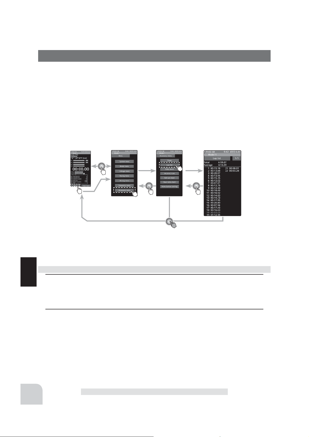
Lap List
Call Lap list when checking the lap memory data (each lap time) memorized by lap timer
(page 132 ) operation.
- After the lap timer is started, the lap time is sequentially memorized at each switch opera
tion.
-The total time and average time are displayed. The faster time is displayed in red characters.
-Lap time data is saved in each model data.
-Up to 80 laps can be saved.
-If the lap timer is reset, the lap list is also cleared.
-
Using the lap memory
1
(Lap memory check)
Function
The lap time list displays 40 laps per page and 80 laps maximum on 2 pages. If there is a
list on page 2, tap [1/2] / [2/2] at the upper right of the screen to change the display of the
page.
Home screen
Menu screen Accessory menu screen
Timer
134
2
When finished, return to the Accessory menu screen by pressing the HOME button.
Lap list
Page 19
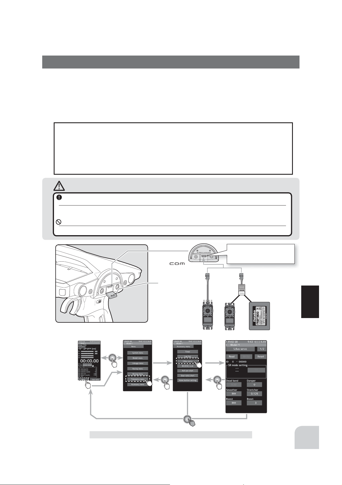
S.Bus Servo
This is a special function which allows Futaba S.BUS/S.BUS2 servo parameter changes to
be set by the T7PX transmitter. However, some data changes require a PC and S-Link software. This function is used by connecting Futaba S.BUS/S.BUS2 servo directly to the transmitter. Use the various optional servo extension cords according to the distance between
the transmitter and servo. (SR mode setting is for T7PX only, it can not be set with S-Link
software.)
-If shutting off while writing the parameters, the servo may fail. Please use this function
with suf¿ cient battery power.
-Power is supplied to the servo from the transmitter, but the corresponding voltage is for
high voltage servo (HV) use. Since an overvoltage will be applied to servos other than
this, connect the corresponding battery to the servo. When the battery is connected, the
supply of power from the transmitter automatically stops.
Caution
When connecting an S-BUS servo that does not support high voltage, connect a battery matched
to the servo specifi cations.
High voltage servo support voltage is supplied from the transmitter. If a servo that does not support high voltage is connected, unreasonable force will be applied to the servo and will cause trouble.
Do not disconnect the servo connector or turn off the transmitter power while writing parameters.
It may cause the servo to malfunction.
Home screen
Menu screen
Communication port.
Cover
Accessory menu screen
Connecting S.BUS/S.BUS2
servo connector to the transmitter Communication port.
Function
S.Bus Servo
S.Bus Servo
135
Page 20
Using the S.Bus servo function
(Preparation)
- Connect the T7PX and S.BUS or S.BUS2 servo in accordance with the connection diagram shown on page 135.
- Connect the battery to a non-high voltage(HV) support S.BUS/S.BUS2 servo.
1
Turn power on the transmitter. "S.Bus servo" menu is displayed referring to the map of
page135.
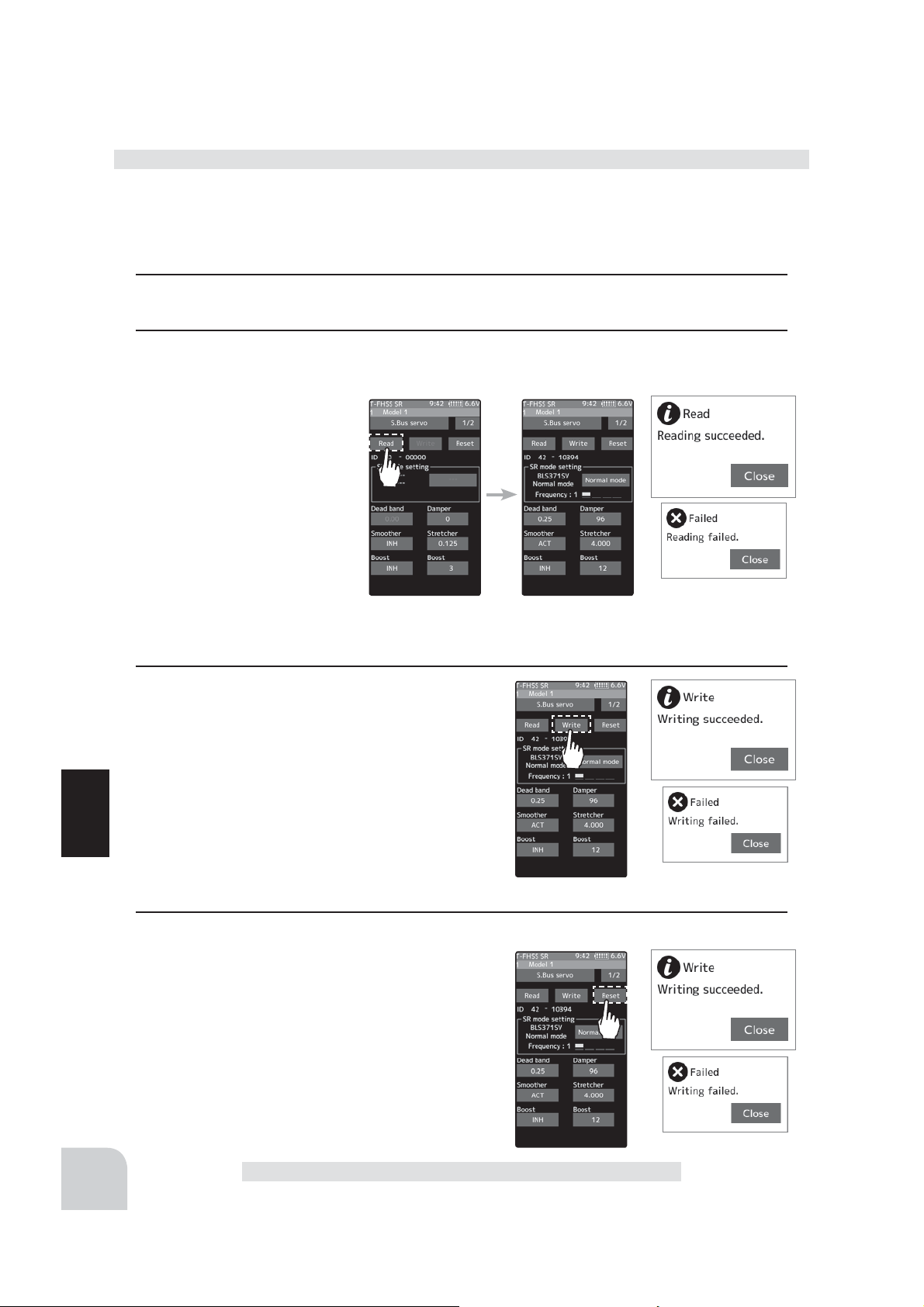
2
(S.BUS/S.BUS2 servo read)
Execute this function to read the connected servo type and the data currently set at the
servo. Tap the [Read]. The
confirmation screen will be
displayed. To execute, tap
[Yes] to hear an electronic
sound and finish setting. To
cancel, select [No] and touch
it.
-"Reading succeeded" is displayed
on the screen and the servo’s ID
cord and currently set contents are
read.
- If "Failed" is displayed on the screen, communication with the servo is not being performed normally.
Check the T7PX and servo connection to servo and repeat [Read]. (Connect the battery to a non-high volt-
age(HV) support servo.)
136
3
(Writing to S.BUS/S.BUS2)
Execute this function to write the setting data to
servo. See pages 138 to139 for the setting data
contents.Tap the [Write]. The confirmation screen
will be displayed. To execute, tap [Yes] to hear an
electronic sound and finish setting. To cancel, select [No] and touch it.
-"Writing succeeded" is displayed on the screen and the setting
Function
data is written to servo.
- If "Failed" is displayed on the screen, communication with the
servo is not being performed normally. Check the T7PX and servo connection to servo and repeat [Write]. (Connect
the battery to a non-high voltage(HV) support servo.)
4
(Initialization)
Write the factory set servo setting data to the connected servo. Tap the [Reset]. The confirmation
screen will be displayed. To execute, tap [Yes] to
hear an electronic sound and finish setting. To cancel, select [No] and touch it.
-"Writing succeeded" is displayed on the screen and the setting
data is written to servo.
- If "Failed" is displayed on the screen, communication with the
servo is not being performed normally. Check the T7PX and
servo connection to servo and repeat "Write". (Connect the
battery to a non-high voltage(HV) support servo.)
S.Bus Servo
Page 21
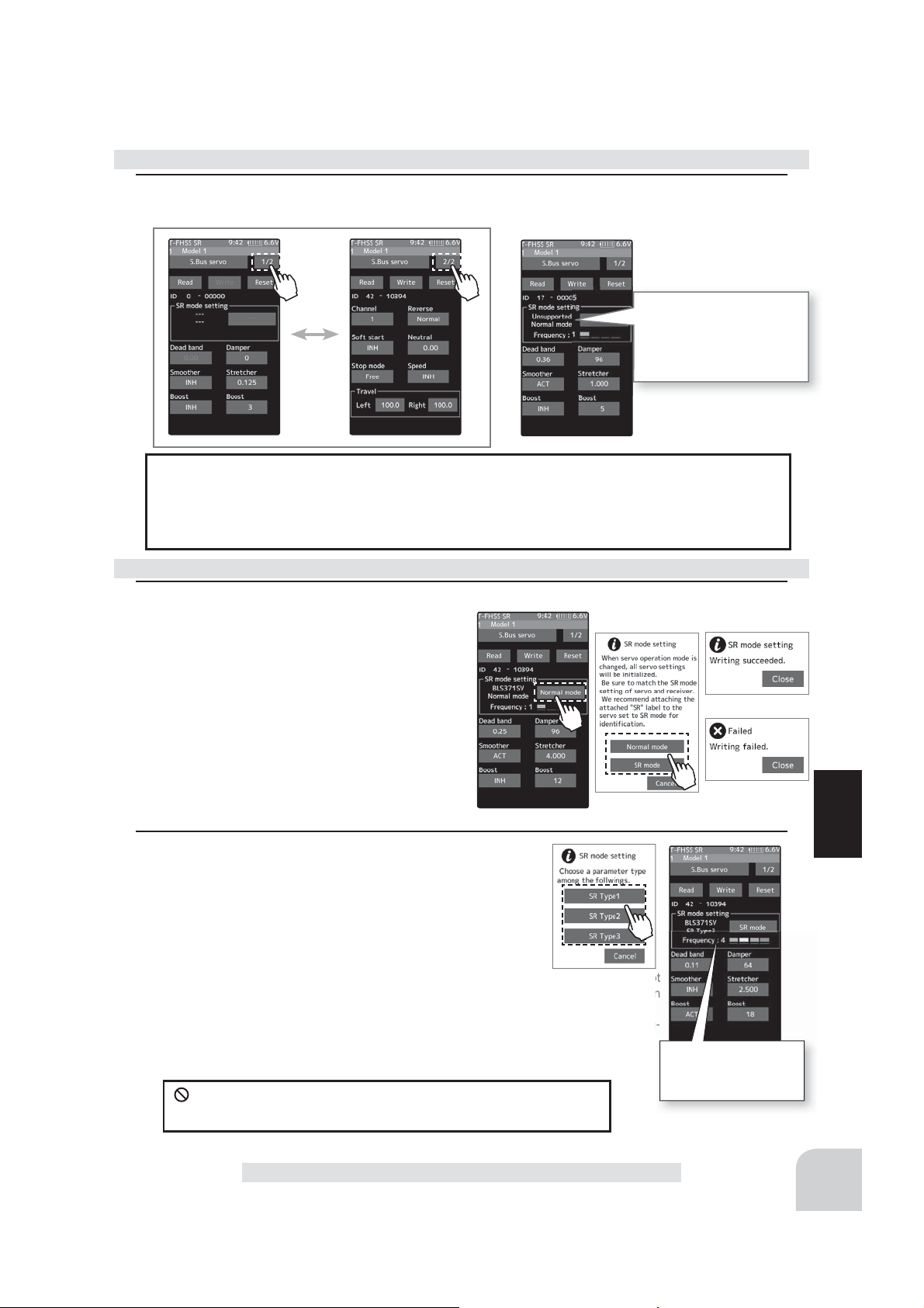
Display data list
1
The type and data of the loaded servo are displayed. Since there are two setting items,
change the page as follows.
When the connected servo
type is not compatible with
the SR mode, "Unsupported Normal mode" is
displayed
- Do not plug in or disconnect servos, or connect other servos while keeping the screen
where data was read by [Read]. Be sure to connect the servo in the state where [Write]
or [Reset] is ¿ nished, or press the Home button to access the accessory menu screen.
- The loaded data can not be written to another servo.
SR mode setting
1
(Writing to servo)
Tap [SR mode] or [Normal mode] of SR mode
setting. A confirmation screen of "Notes on
SR setting" is displayed, so read carefully
and tap [Normal mode] or [SR mode].
- When [Normal mode] is selected, "Writing succeeded"
is displayed on the screen, and the setting data is written to the servo.
- If "Failed" is displayed, communication with the servo is
not performed normally. Check the connection between
the T7PX and the servo, and then execute the write
operation again.
2
(When SR mode is selected by writing to servo)
In the confi rmation screen of "Notes on SR setting", tap
[SR mode], the screen for selecting the SR type is displayed. Three types with different feeling are prepared.
(Please repeat the test and choose the type. )
- "Writing succeeded" is displayed on the screen and the setting
data is written to the servo. If "Failed" is displayed, communication with the servo is not
performed normally. Check the connection between the T7PX and the servo, and then
execute the [Write] operation again.
- For the servo set to SR mode, affi x the attached SR label so that the mode can be recog-
nized.
Do not connect absolutely to the S. BUS channel of all receivers
for the servo set to SR mode. The servo will fail.
S.Bus Servo
Function
The type of servo and
the set SR type are displayed.
137
Page 22

S.BUS function setup
1
On the setting screen of each function, if you tap the item to be set, [-] [reset] [+] will be dis-
played at the bottom of the screen, tap the [-] [+] on the panel Set. Tap[Reset] to return to
the initial value. There are items with no [reset]. In case of selection type, data is switched
by tapping an item.
ID
Displays the ID of the servo whose parameters are to be read. It cannot be changed.
Dead band
The dead band angle at stopping can be
specified.
[Relationship between dead band set value and servo operation]
Small - Dead band angle is small and the
servo is immediately operated by a small signal change.
Large - Dead band angle is large and the servo does not operate at small signal changes.
(Note)
increase and the life of the servo will be shortened.
Damper
The characteristic when the servo is stopped can be set.
When smaller than the standard value, the characteristic becomes an overshoot characteristic. If the value is larger than the standard value, the brake is applied before the stop position.
Especially, when a large load is applied, overshoot, etc. are suppressed by inertia and hunting may occur, depending on the conditions. If hunting (phenomena which cause the servo
to oscillate) occurs even though the Dead Band, Stretcher, Boost and other parameters are
suitable, adjust this parameter to a value larger than the initial value.
[Relationship between damper set value and servo operation]
Small - When you want to overshoot. Set so that hunting does not occur.
Function
Large - When you want to operate so that braking is not applied. However, it will feel like the
servo response has worsened.
(Note)
also be shortened.
If the dead band angle is too small, the servo will operate continuously and the current consumption will
If used in the hunting state, not only will the current consumption increase, but the life of the servo will
138
Smoother
This function makes servo operation smooth. Set it according to your taste. Normally set it
to "ACT". Set it to "INH" when want especially quick operation. When the smoother function was set to "ACT" and the servo was operated the distance up to the target position is
changed in steps so movement is smooth.
Stretcher
The servo hold characteristic can be set. The torque which attempts to return the servo to
the target position when the current servo position has deviated from the target position can
be adjusted.
S.Bus Servo
Page 23

This is used when stopping hunting, etc., but the holding characteristic changes as shown
below.
[Relationship between stretcher and servo operation]
Small - Servo holding force becomes weaker.
Large - Servo holding force becomes stronger.
(Note)
When this parameter is large, the current consumption increases.
Boost/Boost (ON/OFF)
INH : It is the boost ON at the time of low-speed operation. (In the case of usual)
ACT : It is always the boost ON. (When quick operation is hope).
The minimum current applied to the internal motor when starting the servo can be set. Since
a small travel does not start the motor, it essentially feels like the dead band was expanded.
The motor can be immediately started by adjusting the minimum current which can start the
motor.
[Relationship between boost set value and servo operation]
Small - Motor reacts to a minute current and operation becomes smooth.
Large - Initial response improves and output torque increases. However, if the torque is too large, operation will be-
come rough.
Channel
This is the S.BUS system channel assigned to the servo. When connected to the receiver
S-BUS2 connector as an S.BUS system, the channel used by the transmitter is assigned.
When the normal receiver channel is used, channel setting is unnecessary.
Reverse
The direction in which the servo rotates can be changed.
Soft Start
Restricts operation in the specified direction the instant the power is turned on. By using this
setting, the first initial movement when the power is turned on slowly moves the servo to the
specified position.
Neutral
The neutral position can be changed. When the neutral offset is large value, the servo’s
range of travel is restricted on one side.
Stop Mode
The state of the servo when the servo input signal is lost can be specified. The “Hold” mode
setting holds the servo in its last commanded position even if using AM or FM system.
Speed
Speeds can be matched by specifying the operating speed. The speed of multiple servos can be matched without being affected by motor fluctuations. This is effective for load
torques below the maximum torque.
However, note that the maximum speed will not be exceed what the servo is capable of
even if the servos operating voltage is increased.
Function
Travel [Left] / [Right]
The maximum left and right travels centered about the neutral position can be set independently.
S.Bus Servo
139
Page 24
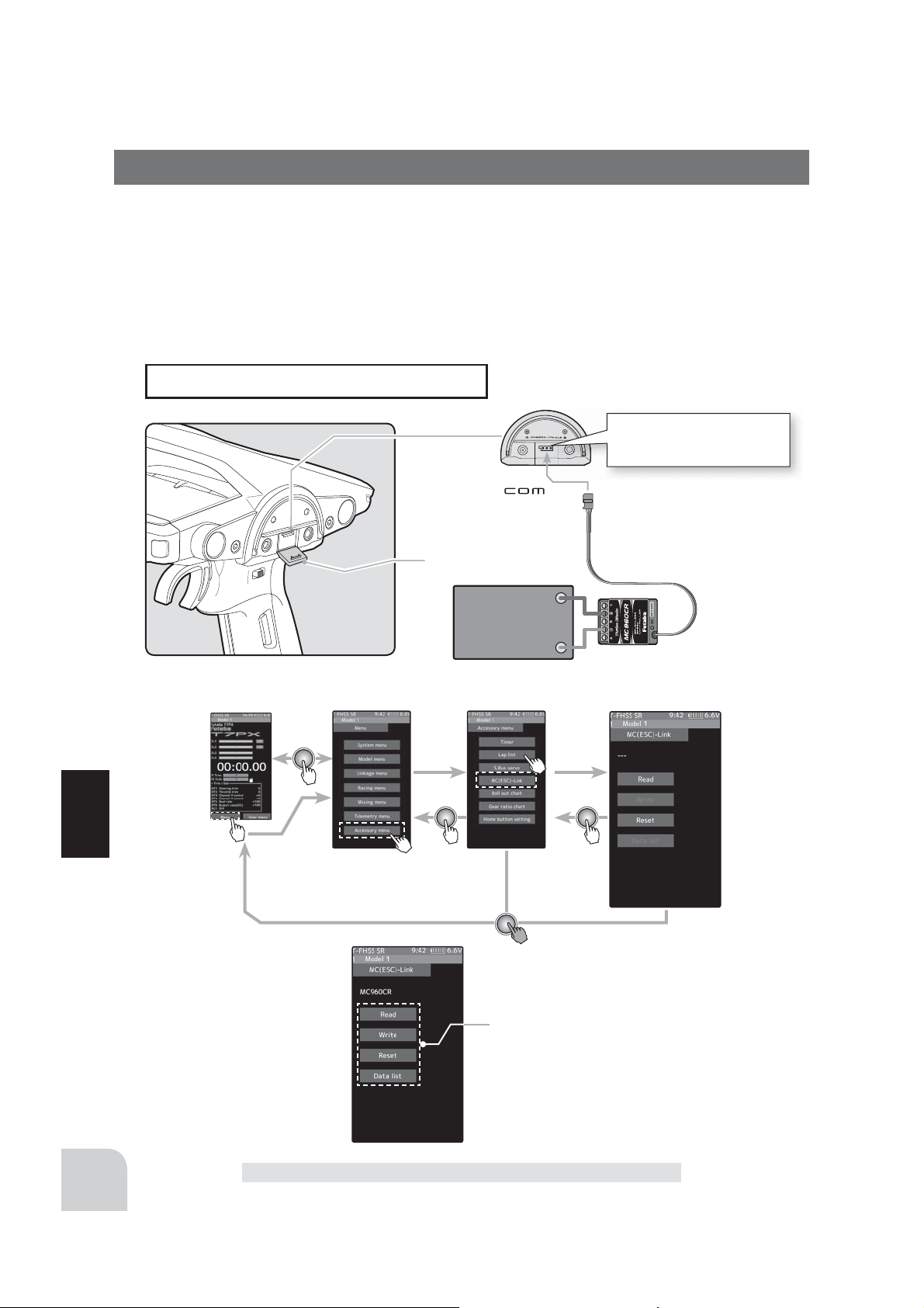
MC Link (ESC Link)
This is a special function which allows Futaba motor controller (MC) data changes to be set
by the T7PX transmitter (MC960CR, MC950CR, MC851C, MC602C, MC402CR, etc.).
However, some data changes require a PC and Link software.
This function is used by connecting ESC directly to the transmitter.
Use the various optional servo extension cords according to the distance between the transmitter and ESC.
-Also connect the battery at the ESC side.
Connecting ESC receiver
connector to the transmitter
Communication port.
Communication port.
Cover
Battery
Home screen
Menu screen Accessory menu screen
Timer
Function
Setup item (after it reads)
Read
Write
Reset
Data list
140
MC Link (ESC Link)
Page 25

Using the ESC Link function
(Preparation)
-
Connect the T7PX and ESC in accordance with the connection diagram shown on page 140.
-Connect the battery to ESC.
1
Turn power on the transmitter. "MC link" menu is displayed referring to the map of page 140.
Set the FET amp power switch to the ON position.
2
(ESC read)
Execute this function to read
the connected ESC type and
the data currently set at the
ESC. Tap the [Read]. The
confirmation screen will be displayed. To execute, tap [Yes] to
hear an electronic sound and
finish setting. To cancel, select
[No] and touch it.
- "Reading succeeded"
- If "Failed"
T7PX and ESC connection and the battery connection to ESC and the ESC power switch and repeat [Read].
is displayed on the screen
is displayed on the screen
, communication with the ESC is not being performed normally. Check the
and the ESC type and currently set contents are read.
3
(Writing to ESC)
Execute this function to write the setting data to
ESC. See pages 143 to 148 for the setting data contents.Tap the [Write]. The confirmation screen will be
displayed. To execute, tap [Yes] to hear an electronic
sound and finish setting. To cancel, select [No] and
touch it.
- "Writing succeeded" is displayed on the screen and the setting
data is written to ESC.
- If "Failed" is displayed on the screen, communication with the
ESC is not being performed normally. Check the T7PX and ESC
connection and the battery connection to ESC and the ESC power switch and repeat [Write].
- Different type ESC data cannot be written. If writing is attempted, "Failed" is displayed on the screen.
4
(Initialization)
Write the factory set ESC setting data to the connected ESC. Tap the [Reset]. The confirmation
screen will be displayed. To execute, tap [Yes] to
hear an electronic sound and finish setting. To cancel, select [No] and touch it.
- "Writing succeeded" is displayed on the screen and the setting
data is written to ESC.
- If "Failed" is displayed on the screen, communication with the
ESC is not being performed normally. Check the T7PX and ESC
connection and the battery connection to ESC and the ESC
power switch and repeat [Write].
Function
MC Link (ESC Link)
141
Page 26

Display data list
-ESC is read referring to the explanation of page 139.
1
Tap the [Data list].
Depending on the ESC type, the setting items are different.
If there are multiple pages, move the page as follows.
To page 1
MC940/960CR page 1
950CR page 1
MC940/960CR page 2 MC940/960CR page 3 MC940/960CR page 4
To page 1
950CR page 2 950CR page 3
Function
601CR/850C page 1
602CR/851C page 1
601CR/602CR/851C page 2 850C page 2
142
402CR page 1
401CR page 1 401CR/402CR page 2
MC Link (ESC Link)
Page 27

PWM frequency (min)
MC950CR :0.5kHz(500Hz) 30kHz(30000Hz)
MC940,960CR :1kHz(1000Hz) 30kHz(30000Hz)
MC401,402CR/601,602C/850,851C :0.1kHz(100Hz) 10kHz (10000Hz)
Same as Link software PWM frequency (at Min. load),
MIn sets the "0" PWM frequency at minimum load.
PWM frequency (max)
MC950CR:0.5kHz(500Hz) 30kHz(30000Hz)
MC940,960CR:1kHz(1000Hz) 30kHz(30000Hz)
MC401,402CR/601,602C/850,851C:0.1kHz(100Hz) 10kHz (10000Hz)
Same as Link software PWM frequency (at Max. load).
MAX sets the PWM frequency at maximum load at the output current
limit value set by Current Limiter.
PWM frequency (brake)
MC402CR/602C/851C (MC401,601,850 cannot be adjusted 2kHz fi xation)
:Normal(2000Hz) /Hard(1000Hz) /Super hard(500Hz)
MC950CR :0.5kHz(500Hz)30kHz(30000Hz)
MC940,960CR :1kHz(1000Hz)30kHz(30000Hz)
Same as Link software Brake PWM at frequency.
This setting can set the brake PWM frequency.
"min" which sets the frequency when the load is small, is set to the high frequency side (large
value) when extension is desired after straightaways and curves.
"max" which sets the frequency when the load is large, is set to the high frequency side (large
value) when you want to suppress the rise from low speed and when motor heating and
commutator roughness are sensed.
When the rise from low speed is poor, and becomes bad even when "max" is set to the low
frequency side, use the log data to check if there was a momentary voltage drop. When you
want to suppress the overall power, lengthen the run time, and otherwise improve effi ciency,
set both "max" and "min" to the high frequency side. When you want to set a fi xed PWM frequency at full range regardless of the load current, set PWM frequency (at Max. load) and
PWM frequency (at Min. load) to the same value.
Dead Band
All type :±2μs~±50μs
Same as Link software Dead Band.
This sets the range (neutral point range) over which the ESC does
not respond to transmitter throttle operation.
The larger the set value, the wider this range.
Dead Band
Position at which motor
starts to run
Point at which brakes start
taking effect
Throttle neutral position
MC Link (ESC Link)
Function
143
Page 28

Low battery protection
MC401,402CR/601,602C/850,851C:2.5V 6.0V
MC950CR/MC940,960CR 2.5V 7.5V
Same as Link software Low Bat Protection.
When the power supply voltage drops, the output current to the motor is limited and supply voltage to the receiver is ensured. When
the power supply voltage drops to the set voltage, a protection circuit operation alarm is activated and output to the motor is cut. The
protection circuit is automatically reset by recovery of the power
supply voltage
Current limiter
MC401,402CR/601,602C/850:50A 300A, INH
MC851C :50A~300A(can not INH)
MC950CR/MC940,960CR:50A~500A, INH
Same as Link software PWM frequency (at Max. load).
MAX sets the PWM frequency at maximum load at the output current limit value set by
Current Limiter.
Current limiter INH/ACT setting
MC950CR and MC940 / 960CR tap INH OR ACT by tapping the current limiter INH/ACT.
The MC851C does not have an INH(Off) settin
Current limit timer
MC401,402CR/601,602C/850,851C:0sec(OFF)240sec
MC940,960CR:0sec(OFF)~240sec (MC950CR can not)
Same as Link software Current Limit timer.
The output current can be limited up to the set time lapse from the start of running. This is
effective in preventing the motor from outputting wasted energy when the voltage is high immediately after the power battery was recharged.
"Current Limiter (time)" sets the time the output current is limited. This function is disabled
when set to "0" sec.
Since the Current Limit Timer starts when
the throttle is operated to the forward side
and current is output to the motor, this func-
Function
tion begins to operate when the motor is
run during trim adjustment, etc.
Current limiter (time)
MC401,402CR/601,602C/850,851C :50A~300A
MC940,960CR :50A~500A (MC950CR can not)
"Current Limit timer" sets the maximum
output current within the time the output
current is limited.
144
MC Link (ESC Link)
Page 29

100
50
0
%
100
50
0
Brake max. duty
All type :0%~100%
Same as Link software Brake Max. Duty.
This setting can set the braking force between the neutral
point and Max brake point.
The larger this value, the greater the braking force. When
set to "0%", the brakes are not effective.
Brake (Reverse) operation
Reverse max. duty
MC401,402CR/MC950CR/MC940,960CR :0%~100%
Same as Link software Reverse Max. Duty.
This setting can set the reverse power between the
neutral point and Max reverse point.
The larger this value, the greater the reverse power.
When set to "0%", the reverses are not
effective.
MC401,402CR
MC950CR
MC940,960CR
Neutral brake
All type :0%~100%
Same as Link software Current Limit timer.
Make this setting when you want to use the brakes at the neutral throttle (OFF) position by
throttle operation. The larger this value, the greater
the braking force. When you want to use the neutral
brake, set this value to "0%".
MC601,602C
MC850,851C
Braking force
Reverse Power
Reverse mode shift level
MC401,402CR/MC950CR/MC940,960CR :0%~100%
Same as Link software Reverse Mode Shift Level.
The reverse operation can be done with the throttle
trigger to be thrown from brake status to the neutral.
The value can set the amount of the brake in order
to switch to the reverse operation.
Forward BOOST
MC401,402CR/MC601,602C/MC851C :0%~100%
Same as Link software Forward Boost (Boost).
Operation near the throttle trigger neutral position
becomes a sharp rise.
Throttle response
FWB "0"
Forward operation
MC401,402CR
MC401,402CR
MC950CR
MC940,960CR
Function
MC601,602
851C
MC Link (ESC Link)
145
Page 30

Reverse cancel
MC401,402CR/MC950CR/MC940,960CR :ACT/INH
Same as Link software Reverse Cancel.
When set to "ACT", reverse operation is not performed.
Robot mode
MC401,402CR/MC950CR/
MC940,960CR :ACT/INH
Same as Link software Robot
Model.
When set to "ACT", brake operation is not performed, there
is only forward and reverse
operation.
MC401,402CR MC940,960CR MC945CR
Brake slope
MC940,960CR/ :0~300
Same as Link software Brake Slope.
This function adjusts the braking effect when the throttle was returned (throttle off). It cancels operation like that called engine brake of actual vehicles.
Brake timer
MC940,960CR/MC950CR :0sec~300sec
Same as Link software Brake Timer.
When the reverse function is used, ordinarily if the trigger is not
moved to the brake (reverse) side and then returned from the brake
operation position to the neutral position, reverse operation will not be
performed. However, when used by intentionally moving the neutral
point to the forward side, if brake operation is repeated, reverse operation may be performed even if the trigger is not returned to the neutral position. The time required to switch to reverse operation can be set to prevent this from occurring.was returned
Function
(throttle off). It cancels operation like that called engine brake of actual vehicles.
Lead angle
MC950CR/ :0~1500
Same as Link software Lead Angle.
The lead angle of the motor can be set at the MC950CR side. However, we recommend that it normally be set to "0". Since this setting is
premised on setting by referring to the speed log by the Link software.
MC940,960CR
146
MC945CR
MC Link (ESC Link)
Page 31

BEC voltage
MC940,960CR/ :6.0V/7.4V
Same as Link software BEC Volt.
The receiver BEC voltage can be selected from 6.0V and 7.4V. Match
the voltage to the rating of the servo connected to the same receiver.
This BEC voltage cannot output a voltage higher than the input voltage.
For instance, if a 6.0V receiver and servo are used with a power supply
voltage of 7.4V or more, set the BEC voltage to 6.0V and when a high
voltage receiver and servo are used, set the BEC voltage to 7.4V.
MC940,960CR
Turbo mode
MC940,960CR/ :Turbo0/Turbo1/Turbo2
Same as Link software Turbo Mode.
This function sets the turbo mode. More power can be displayed by using the turbo mode.
Depending on the setting, the motor and ESC may be damaged so make this setting carefully.
(Note) When "Lead angle use" is INH, lead angle setting will not operate even if set to "Turbo1" or "Turbo2". (Turbo mode disabled, Turbo0=Off)
-Turbo0 mode: (No Lead Angle mode) Lead angle - No
When used in races in which the lead angle setting function is inhibited by
ESC, set to this mode. The lead angle function is disabled the same as if “Lead
angle use” was turned off.
When the lead angle function was disabled by the method described above,
the MC940,960CR shows that the lead angle function is off by blinking a blue
LED at an ON 0.1 second, OFF 0.9 second cycle at the neutral point.
-Turbo1 turbo mode: (Lead Angle mode) Lead angle – Yes
The output can be increased by setting a lead angle.
Depending on the set value, the motor may be damaged so increase the lead
angle value in steps from a small value while observing the conditions.
Turn on “Lead angle use” and adjust the lead angle by “Lead angle” and point A,
B, C, D, E (A, B, C, D, E Lead angle) value.
-Turbo2 power mode: (Power Mode) Lead angle – Yes
Displays still more power than a turbo.
However, since even a motor applies a large load on the ESC, make the lead angle larger in steps from
a small value while observing the conditions.
Turn on “Lead angle use” and adjust the lead angle by “Lead angle” and point A, B, C, D, E (A, B, C, D,
E Lead angle) value.
Power point A
MC940,960CR/ :6.0V/7.4V
Same as Link software Power Point A.
When the turbo mode is power 2 (Power mode) and the lead angle is large, movement may
become stiff when entering the course, etc. In this case, make operation smooth by lowering
the set speed at power point A.
This function is not performed in modes other than Turbo 2.
Function
MC Link (ESC Link)
147
Page 32

Lead angle use
A B C D E
A
B
C
D
E
A B C D E
A
基準進角
B
C
D
E
MC940,960CR :ACT/INH
Same as Link software Lead Angle Use.
This function is effective when Turbo Mode is Turbo1 or
Turn on "Lead angle use"
Turbo2 and sets whether or not lead angle is
used. This setting has priority over the Turbo
Mode setting. When using in races in which
the lead angle function is inhibited by the ESC
set this function to INH.
INH : Lead angle function not used.
ACT : Lead angle used
Point A,B,C,D,E Lead angle
MC940,960CR :0deg~59deg
Same as Link software Boost Angle.
Point A,B,C,D,E Rotation
MC940,960CR :0rpm~120,000rpm
Same as Link software Boost Angle rpm.
When "Lead Angle Use" is turned on the lead angle versus motor speed of the 5 points A to
E can be set. The lead angle can be set up to 59 degrees in 1 degree increments.
The "Lead angle" and "Point A, B, C, D, E Lead angle" relationship is shown on the graphs
below. Graph [1] shows the relationship when the same value is set at "Points A, B, C, D, E
Lead angle" of [1] and [2] and the "Lead angle" was set to "0" and graph [2] shows the relationship when a value other than "0" was set at "Lead angle". As shown in the graphs, [2] is
added to the "Points A, B, C, D, E Lead angle" set lead angle and [1] is added to the "Lead
angle" set lead angle. For example, if "3" is set at Point A and "Lead angle" of [2] is set to "2,
the actual Point A becomes 3+2=5 (deg). Since "Lead angle" of [A] is "0", the actual Point A
also becomes 3+0=3 (deg).
1 (Lead angle ="0") Lead Angle(deg) 2 (Lead angle >"0") Lead Angle(deg)
Function
rpm rpm
When using in races in which the lead angle setting function is inhibited by the ESC, set
Lead angle use" to "INH". The "Lead angle use" setting has priority over "Turbo mode".
"
If "Lead angle use" is set to "INH", the lead angle setting function can be turned off
even if "Turbo mode" is set to "Tu rb o1" or "Tu rb o2".
The MC940,960CR shows that the lead angle setting function is OFF ("0" timing) by
148
blinking a LED.
MC Link (ESC Link)
Page 33

Roll Out Chart
This function is designed for pan cars. The roll out chart can be calculated from input values for the number of teeth of the spur gear and pinion gear, and the tire diameter, and displayed as a table.
Home screen
Use of Roll out chart function
1
(Setting of step of the tire diameter input)
Tap the value button of the [Step]. Value
input buttons appear on the screen. Use
the [+] and [-] buttons to set the step of input
numerical value of tire diameter amount.
- The step amount can be set in the range of 0.1 mm
to 1.0 mm.
Menu screen Accessory menu screen
Roll out chart
Setup item
Pinion
Sper
Step
Diameter
Adjustment buttons
- Adjust with the [+] and [-] buttons.
- Return to the initial value by
tapping the [reset] buttons.
2
(Setting of number of teeth of spur gear)
Tap the value button of the [Super]. Value input buttons appear on the screen. Use the [+] and [-]
buttons to set the spur gear. The roll out is then calculated, and the list is updated.
3
(Setting of number of teeth of pinion gear)
Tap the value button of the [Pinion]. Value input buttons appear on the screen. Use the [+]
and [-] buttons to set the pinon gear. The roll out is then calculated, and the list is updated.
3
(Setting of tire diameter)
Tap the value button of the [Diameter]. Value input buttons appear on the screen. Use the [+]
and [-] buttons to set the tire diameter. The roll out is then calculated, and the list is updated.
4
When fi nished, return to the Accessory menu screen by pressing the HOME button.
Roll Out Chart
Function
149
Page 34

Gear Retio Chart
The Gear Retio Chart can be calculated from input values for the number of teeth of the
spur gear and pinion gear, and secondary gear ratio, and displayed as a table.
Home screen
Use of Roll out chart function
1
(Setting of number of teeth of spur gear)
Tap the value button of the [Super]. Val-
ue input buttons appear on the screen.
Use the [+] and [-] buttons to set the spur
gear. The roll out is then calculated, and the
list is updated.
Menu screen Accessory menu screen
Gear ratio chart
Setup item
Pinion
2nd Gear ratio
Sper
Adjustment buttons
- Adjust with the [+] and [-] buttons.
- Return to the initial value by
tapping the [reset] buttons.
150
2
Function
(Setting of number of teeth of pinion gear)
Tap the value button of the [Pinion]. Value input buttons appear on the screen. Use the [+]
and [-] buttons to set the pinon gear. The roll out is then calculated, and the list is updated.
2
(Setting of number of secondary gear ratio)
Tap the value button of the [2nd gear ratio]. Value input buttons appear on the screen. Use
the [+] and [-] buttons to set the 2nd gear ratio. The roll out is then calculated, and the list is
updated.
3
When fi nished, return to the Accessory menu screen by pressing the HOME button.
Gear Retio Chart
Page 35

Home Button Setting
You can select the screen to display when you push the Home button on the Home screen,
menu or user menu. You can not change the screen to display by push and holding the Home
button from the menu screen or each function screen.
- Push------------------Display menu screen or custom menu screen.
- Long press-----------Trim lock or display the function screen of your choice.
Home screen
How to set the home button
1
(Setting for push)
Tap "Puah" [Menu] or [User menu] to select "Menu" / "User
menu".
Menu screen Accessory menu screen
Home hutton setting
2
(Setting for long press)
Tap "long press".
The function list appears on the home button setting menu screen. Tap and select
the function you want to use. To cancel, tap
[Close].
- Since there are multiple pages, tap the mark and
move the page.
3
When finished, return to the Accessory menu screen by pressing the HOME button.
Home Button Setting
Function
151
Page 36

Telemetry System
With the telemetry system, the running status can be displayed at the transmitter and also
recorded as a data log by installing various sensor units to the chassis
(The T-FHSS SR, S-FHSS and FASST systems do not have a telemetry function.)
-The sensor data can be checked at the transmitter by connecting the telemetry sensor sold
separately to the S.BUS2 connector of the R334SBS receiver.
-To log this information, a start/stop switch is set by switch setting (page 69).
The log data recorded on a microSD card can be converted to CSV format by the telemetry
log converter released at our home page. When copying or moving the log ¿le, always select
both .FLI and .FLD ¿les.
-The ¿gure is an example of connection of a telemetry sensor. The data of up to the follow
ing 3 types of sensor and the receiver power supply voltage can be transmitted by using the
3-way extension cord or double extension cord sold separately.
The receiver power supply can also be connected to the S.BUS2 connector or channel 1 to 4
connector. A receiver power supply voltage sensor is unnecessary.
-
Connection
diagram
Transmitter
Signal
Info
Function
T-FHSS Receiver
Connect to S.BUS2 Connector
-Usable sensor options(As of May 2017)
*Temperature sensor (SBS-01T) Perfect for engine head, etc.
*Temperature sensor (SBS-01TE) Used by attaching to a motor, etc.
*RPM Sensor (SBS-01RM) Measures speed over the 0 to 999,900rpm range.
*Voltage Sensor (SBS-01V) Measures external power supply voltages up to 100V.
*Current sensor (SBS-01C)
*GPS sensor (SBS-01/02G) Detect the GPS and measure the position and speed of the car body.
*Compatibility with non-Futaba sensors (Castle TL0). (Refer to the sensor instruction manual for more information.)
Measures external power supply voltages up to 70V, capacity and consumption capacity.
Info
HUB
Power battery voltage is
displayed at the transmitter.
Info
Switch
Info
voltage
Info
Voltage Sensor
Temperature
Sensor
RPM Sensor
Battery voltage is displayed
at the transmitter.
152
Telemetry System
Page 37

Telemetry
It is necessary to turn on the telemetry on the receiver setting screen to use the telemetry
function. (pace 52) This screen displays and sets the various information from the receiver.
An alarm and vibration can be generated depending on the information. The alarm and
the vibration are set by each information screen. For example, a drop in the voltage of the
receiver battery housed in the model car can be reported by an alarm. The telemetry data
received last is memorized. Therefore, even if the receiver power is turned off, information display, audio guide, and alarms remain until the transmitter power is turned off. The
speech function can be turned on and off with the speci¿ ed switch. See the switch select
function (page 69).
Home screen
Menu screen Accessory menu screen
Telemetry
Receiver-Voltage display
Temperature display
RPM display
EXT-Voltage display
Speed display
EXT-Current display
Using Telemetry function
(Preparation)
The sensor used is connected with the receiver referring to the connection diagram of page 152.
1
(Function ON/OFF)
Tap telemetry (ON) or (OFF) to select ON / OFF.
"OFF" :Telemetry function OFF
"ON" :Telemetry function ON
Function
2
When fi nished, return to the Linkage menu screen by press-
ing the HOME button.
Telemetry
Telemetry function ON
153
Page 38

Telemetry :Receiver Battery Voltage
This function displays and sets the receiver power supply battery. The sensor sold separately
does not have to be installed. The transmitter initial state voltage is also displayed. For a
description of alarm setting when the voltage drops, see the description of the procedure on
this page.
Telemetry
Sets the limiter voltage
(Voltage that sounds an alarm)
Alarm and Vibrator function setup
1
(Limit adjustment)
Tap the [Limit]. Value input buttons appear on the screen.
Use the [+] or [-] button to adjust the limit voltage.
2
(Alarm function setup)
Tap the [Alarm] type and select [Inhibit], [Buzzer]or [Voice].
"Inhibit" :No audible alarm
"Buzzer" :Audible alarm
"Voice" :Voice alarm
Current receiver battery voltage
The minimum and maximum when
powering ON are shown.
Alarm/vibrator ON/OFF and type
setting (The
alarm is generated when the power
supply voltage drops below the set
value.)
The Speech function (ON/OFF)
arrow indicates that an
Adjustment buttons
- Adjust with the [+] and [-] buttons.
- Return to the initial value by
tapping the [reset] buttons.
Setting
- Tap alarm type.
Inhibit/ Buzzer/ Voice
154
3
(Vibrator function setup)
Function
Tap the [Vibrator] type and select [Inhibit], [Type 1], [Type 2],
or [Type 3].
"Inhibit" :No active vibration
"Type1" :Continuous vibration
"Type2" :Intermittent vibration for a long time
"Tyoe3" :Intermittent vibration for a short time
4
(Speech function setup)
Setting
- Tap Vibrator type.
TInhibit/ Type 1/ Type 2/ Type 3
Setting
- Tap (ON) / (OFF).
Tap the "Voice" (ON) or (OFF) to select ON / OFF.
"OFF" :No voice guide
"ON" :Information loaded by voice
5
When fi nished, return to the Telemetry screen by pressing the HOME button.
Telemetry
*The voice guide loading inter-
val is set by sensor menu.
Page 39

Telemetry :The Drive Battery Voltage
With an external power supply, one voltage of the batteries (drive battery, servo power supply battery, etc.) mounted separately in the chassis can be displayed at the transmitter. The
receiver S.BUS2 connector is used to connect the SBS-01V sensor and the battery.
* A drive battery sensor must be installed in the model car. Install and connect the sensor in accordance
with the sensor instruction manual.
Telemetry Current drive battery voltage
The minimum and maximum when
powering ON are shown.
Alarm/vibrator ON/OFF and type
setting (The
alarm is generated when the power
supply voltage drops below the set
value.)
arrow indicates that an
Sets the limiter voltage
(Voltage that sounds an alarm)
Alarm and Vibrator function setup
1
(Limit adjustment)
Tap the [Limit]. Value input buttons appear on the screen.
Use the [+] or [-] button to adjust the limit voltage.
2
(Alarm function setup)
Tap the [Alarm] type and select [Inhibit], [Buzzer]or [Voice].
"Inhibit" :No audible alarm
"Buzzer" :Audible alarm
"Voice" :Voice alarm
3
(Vibrator function setup)
Tap the [Vibrator] type and select [Inhibit], [Type 1], [Type 2],
or [Type 3].
"Inhibit" :No active vibration
"Type1" :Continuous vibration
"Type2" :Intermittent vibration for a long time
"Tyoe3" :Intermittent vibration for a short time
4
(Speech function setup)
Tap the "Voice" (ON) or (OFF) to select ON / OFF.
"OFF" :No voice guide
"ON" :Information loaded by voice
The Speech function (ON/OFF)
Adjustment buttons
- Adjust with the [+] and [-] buttons.
- Return to the initial value by
tapping the [reset] buttons.
Setting
- Tap alarm type.
Inhibit/ Buzzer/ Voice
Setting
- Tap Vibrator type.
TInhibit/ Type 1/ Type 2/ Type 3
Setting
- Tap (ON) / (OFF).
*The voice guide loading inter-
val is set by sensor menu.
Function
5
When fi nished, return to the Telemetry screen by pressing the HOME button.
Telemetry
155
Page 40

Telemetry :RPM
Speed information from an SBS-01RM (telemetry rotation sensor) sold separately is displayed and set at this screen. The speed of the engine, motor, etc. of the chassis while running can be viewed at the transmitter. When the speed becomes higher (lower) than the set
speed, it can be announced by an alarm and vibration.
* A RPM sensor must be installed in the model car. Install and connect the sensor in accordance with the
sensor instruction manual.
Telemetry
Current RPM
The maximum when powering
ON are shown.
Alarm and vibrator ON/OFF and
type setting (The
that an alarm is generated when the
speed drops below the set value and
the
arrow indicates that an alarm is
generated when the speed exceeds
the set value.)
arrow indicates
Sets the limit speed
Upper limit/ lower limit
(Speed that sound an alarm)
Alarm and Vibrator function setup
1
(Gear ratioadjustment)
Tap the [Gear ratio]. Value input buttons appear on the
screen.
Use the [+] or [-] button to adjust the Gear ratio.
2
(Limit adjustment)
Tap the "
" [
Limit] or "
Use the [+] or [-] button to adjust the limit voltage.
3
(Alarm and vibrator function setup)
Function
Tap the "
"Inhibit":No audible alarm/ "Buzzer":Audible alarm/ "Voice":Voice alarm
Tap the "
"Inhibit" :No active vibration
"Type1" :Continuous vibration
"Type2" :Intermittent vibration for a long time
"Tyoe3" :Intermittent vibration for a short time
" / ""
[Alarm] type and select [Inhibit], [Buzzer]or [Voice].
" / ""
[Vibrator] type and select [Inhibit], [Type 1], [Type 2], or [Type 3].
Gear ratio
The Speech function (ON/OFF)
" [
Limit]. Value input buttons appear on the screen.
Adjustment buttons
- Adjust with the [+] and [-] buttons.
- Return to the initial value by
tapping the [reset] buttons.
156
4
(Speech function setup)
Tap the "Voice" (ON) or (OFF) to select ON / OFF.
"OFF" :No voice guide
"ON" :Information loaded by voice
5
When fi nished, return to the Telemetry screen by pressing the HOME button.
Telemetry
*The voice guide loading inter-
val is set by sensor menu.
Page 41

Telemetry :Temperature
This screen displays and sets the temperature information from an SBS-01T (telemetry
temperature sensor) sold separately. The temperature of the engine, motor, amp, etc. of the
chassis while running can be viewed at the transmitter. When the temperature becomes
higher (lower) than the set value, it can be announced by an alarm and vibration.
* A temperature sensor must be installed in the model car. Install and connect the sensor in accordance
with the sensor instruction manual.
Telemetry
Current temperature
The minimum and maximum the
when powering ON are shown.
Limit temperature setting
(Temperature that sounds
an alarm)
Alarm and Vibrator function setup
1
(Limit adjustment)
Tap the "
" [
Limit] or "
" [
Limit]. Value input buttons appear on
the screen.
Use the [+] or [-] button to adjust the limit voltage.
2
(Alarm and vibrator function setup)
Tap the "
" / ""
[Alarm] type and select [Inhibit], [Buzzer]or
[Voice].
"Inhibit":No audible alarm/ "Buzzer":Audible alarm/ "Voice":Voice alarm
Tap the "
" / ""
[Vibrator] type and select [Inhibit], [Type 1],
[Type 2], or [Type 3].
"Inhibit" :No active vibration
"Type1" :Continuous vibration
"Type2" :Intermittent vibration for a long time
"Tyoe3" :Intermittent vibration for a short time
Alarm and vibrator ON/OFF and
type setting (The
that an alarm is generated when the
speed drops below the set value and
the
arrow indicates that an alarm is
generated when the speed exceeds
the set value.)
The Speech function (ON/OFF)
Adjustment buttons
- Adjust with the [+] and [-] buttons.
- Return to the initial value by
tapping the [reset] buttons.
Setting
- Tap alarm type.
Inhibit/ Buzzer/ Voice
Setting
- Tap Vibrator type.
TInhibit/ Type 1/ Type 2/ Type 3
arrow indicates
Function
3
(Speech function setup)
Tap the "Voice" (ON) or (OFF) to select ON / OFF.
"OFF" :No voice guide
"ON" :Information loaded by voice
4
When fi nished, return to the Telemetry screen by pressing the HOME button.
Telemetry
Setting
- Tap (ON) / (OFF).
*The voice guide loading inter-
val is set by sensor menu.
157
Page 42

Telemetry :The Drive Battery Electric Current
When the SBS-01C (electric current sensor) sold separately is mounted on the vehicle, the
electric current, voltage and consumption capacity of the power battery, etc., can be displayed.
* A drive battery electric current sensor must
be installed in the model car. Install and
connect the sensor in accordance with the
sensor instruction manual.
Current drive battery electric
current
The minimum and maximum
when powering ON are shown.
Telemetry
Alarm and vibrator ON/OFF and
type setting (The
that an alarm is generated when
the electric current drops below
the set value and the
cates that an alarm is generated
when the electric current exceeds
the set value.)
Reset consumption capacity
The Speech function (ON/OFF)
Current drive battery voltage
The minimum and maximum
when powering ON are shown.
Alarm and vibrator ON/OFF and
type setting (The
that an alarm is generated when
the battery voltage drops below
the set value and the
cates that an alarm is generated
when the battery voltage exceeds
the set value.)
Reset consumption capacity
arrow indicates
arrow indi-
arrow indicates
arrow indi-
158
The Speech function (ON/OFF)
Function
-Upper side:
Current current / voltage /
consumption capacity display.
-Lower:
This is a display of the
minimum value / maximum
value of the measured current / voltage / consumption
capacity after turning on the
transmitter power.
* Tap the min / max display
button to restart the measurement.
The Speech function (ON/OFF)
Telemetry
Current drive battery capacity
The minimum and maximum
when powering ON are shown.
Alarm and vibrator ON/OFF and
type setting (The
that an alarm is generated when
the battery capacity drops below
the set value and the arrow
indicates that an alarm is generated when the battery capacity
exceeds the set value.)
Reset consumption capacity
arrow indicates
Page 43

Alarm and Vibrator function setup
1
(Limit adjustment)
Tap the "
" [
Limit] or "
" [
Limit]. Value input buttons appear on
the screen.
Use the [+] or [-] button to adjust the limit voltage.
Adjustment buttons
- Adjust with the [+] and [-] buttons.
- Return to the initial value by
tapping the [reset] buttons.
2
(Alarm and vibrator function setup)
Tap the "
" / ""
[Alarm] type and select [Inhibit], [Buzzer]or
Setting
- Tap alarm type.
Inhibit/ Buzzer/ Voice
[Voice].
"Inhibit":No audible alarm/ "Buzzer":Audible alarm/ "Voice":Voice alarm
Tap the "
[Type 2], or [Type 3].
"Inhibit" :No active vibration
"Type1" :Continuous vibration
"Type2" :Intermittent vibration for a long time
"Tyoe3" :Intermittent vibration for a short time
3
(Speech function setup)
Tap the "Voice" (ON) or (OFF) to select ON / OFF.
"OFF" :No voice guide
"ON" :Information loaded by voice
4
When finished, return to the Telemetry screen by pressing the HOME button.
" / ""
[Vibrator] type and select [Inhibit], [Type 1],
Setting
- Tap Vibrator type.
TInhibit/ Type 1/ Type 2/ Type 3
Setting
- Tap (ON) / (OFF).
*The voice guide loading inter-
val is set by sensor menu.
Reset consumption capacity display
Unless the reset button of SBS-01C is pressed, the consumption capacity measured by SBS-
01C is maintained and displayed as “integrated capacity” on the screen. If you wish to measure the consumption capacity for one run, it is possible to reset the consumption capacity
display on the transmitter by the next operation. However, the record of the integrated capacity of the SBS-01C main body cannot be reset by the function which resets the transmitter
display.
1
(Reset operation)
Tap the [Reset], the consumption capacity display is reset to 0. The
consumption capacity from the time of reset is displayed until you
reset it again. If you reset the consumption capacity by pressing the
reset button of SBS-01C, the consumption capacity display on the
transmitter is also reset.
2
When finished, return to the Telemetry screen by pressing the
HOME button.
The reset operation on the transmitter resets the integrated capacity display on the T7PX. It does
not reset the integrated capacity on the SBS-01C. The consumption capacity measurement range
of SBS-01C is 32767mAh maximum. When this value is exceeded, the consumption capacity display on the transmitter is also reset automatically. Depending on the timing, reset may occur during
measurement. Therefore, make sure to reset the integrated capacity on the SBS-01C before the
integrated capacity display reaches 32767mAh.
Telemetry
Function
159
Page 44

Telemetry :GPS
When SBS-01G/02G (GPS sensor) sold separately is mounted on the car body, you can receive radio waves from GPS satellites and display information on the position and speed of
the car.
* A GPS sensor must be installed in the model car. Install and connect the sensor in accordance with the
sensor instruction manual.
* When powered up, the SBS-01/02G begins to acquire GPS satellite data. This process can take several
minutes. Please do not move the model during this process. During acquisition, the LED on the SBS01/02G will blink green; after the satellite’s signals have been acquired, the LED will become solid green,
and the GPS signal strength display on the transmitter will show three bars.
Moving the model before the satellites are fully acquired will cause a delay in acquiring the satellite signal.
* Since GPS satellites are basically used, accurate distances and speeds may not be displayed depending
on the surrounding environment or the conditions of the course.
Telemetry
The Speech function
(ON/OFF)
Current distance
The maximum when powering
ON are shown.
* Tap the max display button to
restart the measurement.
Alarm and vibrator ON/OFF and
type setting (The arrow indicates
that an alarm is generated when
the minimum distance below the
set value and the arrow indicates
that an alarm is generated when
the distance exceeds the set
value.)
Tap the [Preset reference]. Sets
the current car position as the
starting point.
160
Current speed
The maximum when powering
ON are shown.
Function
This indicates the
receiving accuracy
from a GPS Satellite.
The position of the present model is displayed.
-Upper side:
Current distance and speed display.
-Lower:
This is a display of the maximum value of the
measured distance and speed after turning on
the transmitter power.
* Tap the max display button to restart the mea-
surement.
The Speech function
(ON/OFF)
Telemetry
* Tap the max display button to
restart the measurement.
Alarm and vibrator ON/OFF and
type setting (The arrow indicates
that an alarm is generated when
the minimum speed below the
set value and the arrow indicates
that an alarm is generated when
the speed exceeds the set value.)
Tap the [Preset reference]. Sets
the current car position as the
starting point.
Page 45

Alarm and Vibrator function setup
1
(Limit adjustment)
Tap the "
" [
Limit] or "
" [
Limit]. Value input buttons appear on
the screen.
Use the [+] or [-] button to adjust the limit voltage.
Adjustment buttons
- Adjust with the [+] and [-] buttons.
- Return to the initial value by
tapping the [reset] buttons.
2
(Alarm and vibrator function setup)
Tap the "
" / ""
[Alarm] type and select [Inhibit], [Buzzer]or
Setting
- Tap alarm type.
Inhibit/ Buzzer/ Voice
[Voice].
"Inhibit":No audible alarm/ "Buzzer":Audible alarm/ "Voice":Voice alarm
Tap the "
[Type 2], or [Type 3].
"Inhibit" :No active vibration
"Type1" :Continuous vibration
"Type2" :Intermittent vibration for a long time
"Tyoe3" :Intermittent vibration for a short time
3
(Speech function setup)
Tap the "Voice" (ON) or (OFF) to select ON / OFF.
"OFF" :No voice guide
"ON" :Information loaded by voice
4
When finished, return to the Telemetry screen by pressing the HOME button.
" / ""
[Vibrator] type and select [Inhibit], [Type 1],
Setting
- Tap Vibrator type.
TInhibit/ Type 1/ Type 2/ Type 3
Setting
- Tap (ON) / (OFF).
*The voice guide loading inter-
val is set by sensor menu.
How to set the reference position
It takes a while for GPS to be measured after turning on the power. Please wait until the LED of
the GPS sensor turns on green without moving the car body. If the distance display does not
stabilize even after the green LED lights up, or if you set a new reference value for the place
where the car body moved, reset the reference position.
1
(reset operation)
Since either the distance / speed screen can be used, tap [Reference
position setting]. The distance is reset. After that, the distance from
the point where resetting is done is displayed until tapping [Reference
position setting] again.
Telemetry
Function
161
Page 46

Sensor List
This menu registers the telemetry sensors used with the transmitter. When only one of a
certain type of sensor is used, this setting is unnecessary and the sensor can be used by
simply connecting it to the S.BUS2 port of the transmitter.
When using 2 or more of the same kind of sensor, they must be registered here.
What is a slot?
Servos are classi¿ ed by CH, but sensors are classi¿ ed in units called "slot". There are
slots from No. 1 to No. 31. Using a sensor which uses two or more slots, the required
number of slots is automatically assigned by setting up a start slot. When 2 or more of
the same kind of sensor are used, the sensors themselves must allocate unused slots and
memorize that slot.
Home screen
Function
Menu screen Telemetry menu screen
Sensor is not registered
in slot.
Slot
State with registered sensor
Change to “---------”, you can make it
an empty slot.
Sensor list
162
Slot number
About the slots that can be used.
As shown in the table below, the current sensor requires three consecutive slots, and the GPS sensor requires 8
consecutive slots. The GPS sensor (SBS - 01 / 02G) has a starting slot of 8.16.24.
sensor
TEMP(SBS-01T) 1 slot 1~31
RPM(SBS01RM) 1 slot 1~31
Voltage(SBS-01V)
Current(SBS-01C)
GPS(SBS-01/02G) 8 slot 8,16,24
The required number of
slots
2 slot
2 slot
The number which can be used as a start slot
1,2,3,4,5,6,8,9,10,11,12,13,14,16,17,18,19,
20,21,22,24,25,26,27,28,29,30
1,2,3,4,5,6,8,9,10,11,12,13,16,17,18,19,20,
21,24,25,26,27,28,29
Sensor List
Page 47

How to change start slot and set empty slot
1
(Start slot selection)
Tap [Slot], the list of sensors that can be
registered in the start slot will be displayed.
Sensors that can not be changed are not
displayed.
2
(Sensor selection)
From the sensor list, tap the sensor you
want to register in the start slot. To set as
an empty slot, tap [---------]. This completes
the change.
Start slot selection
- Tap the slot
Sensor selection
- Tap the sensor
3
When finished, return to the Sensor list screen by pressing the HOME button.
Function
Sensor List
163
Page 48

Sensor
With this menu, you can display the telemetry meter on the home screen.
Also, you can register a telemetry sensor in the transmitter. When using each sensor of the
initial setting one by one, setting here is unnecessary. You can use it by connecting the purchased sensor to the S.BUS 2 port of the receiver. If you use multiple sensors of the same
type, such as temperature sensor for both battery and motor, you need to register that sensor
in the transmitter.
Home screen
Menu screen Telemetry menu screen
Display of sensor list screen (page 162)
Register multiple sensors of the same type (page 165)
Register one additional sensor of the same type (page 166)
Change slot number of one registered sensor (page 167)
Read voice guide and set interval time (page 168)
Sensor
164
Setting the recording interval time for log data (page 168)
Function
Display telemetry meter on home screen (page 168)
Sensor
Page 49

Sensor Reload
When using multiple sensors of the same type the sensors must be registered in the transmitter. Connect all the sensors to be used to the T7PX as shown in the ¿ gure at the right
and register them by the following procedure. The ID of each sensor is registered in the
transmitter.
To load the sensor, connect all sensors to be used to the T7PX communication port as
shown below. Power supply is unnecessary. Also, to clear all sensor registration, execute
this [Reload] function without connecting sensor. The registration is cleared and all the
slots in the sensor list are unregistered.
All the sensors to be used
are connected to the
T7PX.
Communication port.
Cover
How to change start slot and set empty slot
1
(Start slot selection)
Tap the [Reload], The confi rmation screen will be displayed. To execute, tap [Yes] to hear an
electronic sound and fi nish setting. To cancel, select [No] and touch it. If "Success" appears
on the screen, reroad is complete.
Sensor
Sensor
Sensor
Function
2
When fi nished, return to the Telemetry screen by pressing the HOME button.
Sensor
165
Page 50

Sensor Register
This function registers additional sensors. Connect the sensor as shown in the ¿ gure and
register as follows. The sensor ID is registered in the transmitter.
This function is set when adding one telemetry sensor of the same type.
Connecting S.BUS/S.BUS2
servo connector to the
T7PX.
Communication port.
Cover
Sensor (The battery is not necessary)
How to change start slot and set empty slot
1
(Start slot selection)
Tap the [Register], The confi rmation screen will be displayed. To execute, tap [Yes] to hear
an electronic sound and fi nish setting. To cancel, select [No] and touch it. If "Success" appears on the screen, registration is complete. If registering a sensor that has already been
registered is attempted, the message "Failed; The same sensor has been registered" will be
displayed. If the message "Failed; The connected sensor is not ready." is displayed, check
the sensor connection. If it is securely connected, the sensor or the transmitter may be
faulty.
166
Function
Confi rm sensor connection
2
When fi nished, return to the Telemetry screen by pressing the HOME button.
Sensor
Page 51

Change Slot
This procedure changes the slot number of one registered sensor. Connect the sensor as
shown in the ¿gure (page 166), and change slot number.
This function is set when using multiple telemetry sensors of the same type.
Sensor slot change
1
(Change)
Tap the [Change slot]. The sensor details screen is displayed. Tap the [Read]. The confirmation screen will be displayed. To execute, tap [Yes] to hear an electronic sound and finish
reading. To cancel, select [No] and touch it. If "Reading suceeded" appears and the current
sensor information is displayed.
2
(Number setting)
Tap the value button of the [Start slot #].
Value input buttons appear on the screen.
Use the [+] and [-] buttons to set the start
slot number.
3
Tap the [Write]. When "Writing suceeded"
message is displayed, the number change
is completed.
Setting button
Setting with the [+] and [-] but-
tons.
Function
4
When finished, return to the Sensor screen by pressing the HOME button.
Sensor
167
Page 52

Speech guide interval and log data interval setting
You can set the interval at which to read the voice guide of telemetry information and the
interval at which log data is recorded.
Setting interval
1
(Setting of speech interval)
Tap the value button of the [Speech interval]. Value input buttons appear on
the screen. Use the [+] and [-] buttons to
adjust the speech interval amount.
Adjustment buttons
- Adjust with the [+] and [-] buttons.
- Return to the initial value by
tapping the [reset] buttons.
Speech interval
0~ 30 sec
Initial value: 0
2
(Setting of logging interval)
Tap the value button of the [Logging interval]. Value input buttons appear on the
screen. Use the [+] and [-] buttons to adjust
the logging interval amount.
3
When finished, return to the Telemetry screen by pressing the HOME button.
Telemetry meter display on home screen
Telemetry information on the home screen, graphic meter can be displayed.
Function
Display of telemetry meter
1
(Function ON/OFF)
Tap "Home screen" (ON) or (OFF) to select
ON / OFF.
"OFF" :Telemetry meter not displaed
"ON" :Telemetry meter display
Adjustment buttons
- Adjust with the [+] and [-] buttons.
- Return to the initial value by
tapping the [reset] buttons.
Logging interval
0~ 30 sec
Initial value: 0
168
3
When finished, return to the Telemetry screen by pressing the HOME button.
Sensor
Page 53

Telemetry meter display settings
Five telemetry meters displayed on the home screen are displayed. You can select the sensor
to display and set the range of display data. It can be set for each meter.
Home screen
Tap meter to set display
range etc.
Tap to select sensor
to display
Display the screen to select
the sensor to be displayed.
Set the upper limit / lower
limit displayed on the meter.
When the sensor to be
displayed can measure
multiple data, select
which data to display.
In the case of a current sensor,
for example, it is possible to select
from current / voltage / consumption capacity, to select data to display from a plurality of data.
It is also possible to display all
three data with separate meters.
Tap the value button of the [Max.]
and [Min]. Value input buttons appear on the screen. Use the [+] and
[-] buttons to adjust the upper limit
and lower limit amount.
Function
Sensor
169
Page 54

Model Select
Forty model data (model data for 40 R/C cars) can be saved in the T7PX transmitter and
used when the relevant model data is called. However, models copied in the microSD card
can not be used by directly calling from the card. Please copy it to the T7PX main unit
when using it.
Home screen
Menu screen Model menu screen
Model where green cursor is
currently in use
Since there are multiple pages,
tap the
page.
mark and move the
Model select
170
Using the model selection function
1
(Model memory selection)
You can choose from 8 models on 1 page and 40 models on
5 pages. Tap the
Function
the page.
2
(Model selection execution
Tap the [Model name] to use, a confi rmation screen will be displayed saying "Are
you sure?" To execute, tap [Yes], a beep
sounds and the change is completed and
the home screen is displayed. To cancel,
tap [No] and tap.
If the model name of the home screen is changed,
-
model selection is completed.
3
When fi nished, return to the Model menu screen by pressing the HOME button.
mark at the bottom of screen to move
Model Select
Model #.
M1~M40
Model selection
- Tap the [Model name]
Page 55

Model Copy
The contents of the model memory can be copied to another model memory. The contents
can also be saved or stored on a microSD card for copying to another T7PX.
Home screen
Model copying
1
(Copy source model selection)
You can choose from 8 models on 1 page and 40 models on
5 pages. Tap the
the page.
2
(Model selection execution
Tap the "Copy from" [model name], select
the model list so it will tap. The source
model is selected and the model list is
closed. The list is the same design as the
model select and the way of moving the
page is the same. If a microSD card is installed in the T7PX main unit, a button for
selecting either the model inside the T7PX
main unit or the model inside the microSD
card will be displayed, so tap to select it. To cancel, press the
Home button to return to the model copy screen.
Menu screen Model menu screen
mark at the bottom of screen to move
Model copy
Copy source
Tap to select from the list
Function
Tap to select the model of
the T7PX main body or the
model inside the SD card.
Tap to view the model in
the SD card
Model copy
171
Page 56

3
(Copy destination model selection)
Tap the "Copy to" [model name], select the
model list so it will tap. The source model
is selected and the model list is closed.
-The model currently in use cannot be selected.
-Since the copy destination cannot be overwritten
when it is in a microSD card, a models list is not displayed and the model is saved directly to the microSD
card.
Copy destination
Tap to select from the list
4
(Copy execution)
Tap the [Copy], The confirmation message
"Are you sure" appears. To execute copy,
tap [Yes] and to cancel copy, select [No].
When the copy destination model name
becomes the same name as the copy
source, copying is complete.
5
When finished, return to the Model menu screen by pressing the HOME button.
microSD card storage destination
Function
When a microSD card is installed in the T7PX, a folder called “Futaba” is created, and folders
called “LOG” and “MODEL” are created in it. The “MODEL” folder contains the model data.
Copy execution
Tap the [Copy]
172
Model data
When the T7PX model data is copied, and the copy source data is selected from the model data stored in the microSD, a model list like that shown
at the left is displayed.
Model copy
Page 57

Model Name
This function allows you to assign a ten character name to each model memory.
Home screen
Move cursor
Menu screen Model menu screen
Deletion and cancellation of
characters (Undo)
Tap to select characters
Selection of alphabet / number / "kana"
Model copy
Setting the model name and user name
1
(Moving the cursor to the character you want to change.)
In the model name, tap [
], [ ] to move the cursor and
select the character of the model name you want to set or
change. A vertical line cursor is displayed before the selected
character.
2
(Selection of characters to use)
Select the character to use from the character list. When you
decide the character to use, tap it. The character is determined and the character string of the model name moves to
the right. If you tap [BS], the left character of the vertical line
cursor will be deleted. To redo, tap [Undo].
3
When fi nished, return to the Model menu screen by pressing
the HOME button.
Model Name
Name cursor movement
Use the [
the cursor. Also, when you decide a character, when the cursor position of the model name
moves to the right, the cursor
position of the model name
moves to the right
Select / determine character
Select a character, tap it to de-
termine the character
] / [ ] tap to move
Function
173
Page 58

Model Delete (Model saved on microSD card)
This function deletes model data saved on the microSD card.
Model deletion is displayed on the menu only when microSD card is set in the T7PX card
slot.
Home screen
How to delete model data in microSD card
1
(selection of model data)
If the number of models that does not fit on one page is
memorized, tap [1/2] in the upper right corner to move the
page.
If there are 2 pages, it will be displayed as [1/2] / [2/2], if
there are 5 pages, it will be displayed as [1/5] to [5/5].
Menu screen Model menu screen
Model select
174
2
(execution of model deletion)
Tap the model you want to delete. A confirmation message "Are you sure?" appears.
Tap [Yes] to execute the deletion, or [No] to
Function
cancel.
"Deleting succeded" is displayed and deletion is completed.
3
When finished, return to the Model menu screen by pressing the HOME button.
Model Delete (Model saved on microSD card)
Delete execution
Tap the [model data]
Page 59

Data Reset
This function resets the contents of the currently called model memory.
The reset method can be selected from among the 4 types described below. These resets do
not initialize the adjuster function and system function.
-Model data
Initializes only the function setting data. The direct menu function is not initialized.
-User menu
Initializes the user menu function. Other settings are not initialized.
-Tel emet ry
Telemetry related setup data is initialized.
-All data
Initializes the direct selection function, receiver setting function and the setting data of
each function.
Home screen
Data Reset
1
1 (Execution of reset)
Select the type you want to reset and tap.
A confirmation message will be displayed
as "Are you sure?" If you want to execute,
tap [No] to cancel with [Yes]. Reset is now
complete.
Menu screen Model menu screen
Data reset
Reset execution
Tap the [reset type]
Reset type
-Model data
-User menu
-Telemetry
-All data
Function
2
When finished, return to the Model menu screen by pressing the HOME button.
Data Reset
175
Page 60

Display
Backlight brightness, dimming time etc. setting and tap panel correction menu.
There is also a tap panel sensitivity adjustment.
Display setup
1
2
Function
Home screen
(Backlight decrease brightness adjustment)
Tap the value button of the [Backlight max, brightness] or
[Backlight min, brightness]. Value input buttons appear on the
screen and use the [+] and [-] buttons to adjust the backlight
decrease brightness amount.
(Backlight decrease time)
You can set a time period to decrease the LCD backlight.
This function counts the period that the touch panel has been
not operated. This time can be set by one second steps. You
can also turn off the backlight decrease if you like.
Tap the value button of the [Backlight decrease time]. Value
input buttons appear on the screen and use the [+] and [-]
buttons to adjust the backlight decrease time amount.
Menu screen System menu screen
Timer
Adjust button
Adjust with the [+] and [-] but-
tons.
- Return to the initial value by
tapping the [reset] buttons.
176
3
(Tap panel correction)
Tap [Calibration]. It will be a black screen with a white + mark
at the center of the screen. Tap on the intersection of that +
mark in order, using 5 stylus pens etc of our company.
To cancel, press the Home button to return to the display setting screen.
Display
Tap the + mark in
5 places in order.
Page 61

4
(Tap panel sensitivity adjustment)
You can adjust the sensitivity of the tap panel.
Tap the value button of the [Sensitivity]. Value input buttons
appear on the screen and use the [+] and [-] buttons to adjust the sensitivity of the touch panel.
5
(Touch Panel Vibrate ON / OFF)
The vibrate can be operated by the operation of the touch
panel. Tap on the "Vibrator" (ON ) or (OFF) and select ON /
OFF.
"OFF" :Function OFF
"ON" :Function ON
6
(Setting of start / end screen)
Set whether or not to display the Futaba T7PX logo mark on
startup and exit screens. If it is set to OFF, it disappears.
Tap on the "Opening demo" (ON ) or ( OFF) and select ON /
OFF.
"OFF" :Function OFF
"ON" :Function ON
Adjust button
Adjust with the [+] and [-] but-
tons.
- Return to the initial value by
tapping the [reset] buttons.
Sensitivity
10~100
Initial value : 30
Setting
- Tap (ON) / (OFF).
Setting
- Tap (ON) / (OFF).
7
When finished, return to the System menu screen by press-
ing the HOME button.
Function
Display
177
Page 62

Information
With this system information, you can select user name setting, display language, use
unit of telemetry information. Also displays the software version.
Home screen
Move cursor
Menu screen System menu screen
Deletion and cancellation of
characters (Undo)
Tap to select characters
Information
178
Setting the user name
1
(Moving the cursor to the character you want to change.)
In the model name, tap [ ], [ ] to move the cursor and
Function
select the character of the model name you want to set or
change. A vertical line cursor is displayed before the selected
character.
2
(Selection of characters to use)
Select the character to use from the character list. When you
decide the character to use, tap it. The character is determined and the character string of the model name moves to
the right. If you tap [BS], the left character of the vertical line
cursor will be deleted. To redo, tap [Undo].
3 When fi nished, return to the Model menu screen by pressing the HOME button.amount.
3
When fi nished, return to the System menu screen by pressing the HOME button.
Information
Selection of alphabet / number / "kana"
Name cursor movement
Use the [
the cursor. Also, when you decide a character, when the cursor position of the model name
moves to the right, the cursor
position of the model name
moves to the right
Select / determine character
Select a character, tap it to de-
termine the character
] / [ ] tap to move
Page 63

Language setting
1
(Language select)
Tap [Language], a list of languages will
be displayed on the screen. If you tap the
language you want to use from the list, the
language display will be changed and you
will be taken to the home screen.
-The available languages will be added in the future.
Units system setting
1
(Units system setting)
Tap [Unit System] and set it to either the
metric method or the yard / pound method.
Language select
Tap to select from the list
Setting
- Tap Units system
Meric system
Yard-pound system
Display of manufacturer information and open source license
1
(Units system setting)
Tap [Open source license], displays the manufacturer information and the license information of the font used in the system.
3
When finished, return to the System menu screen by pressing the HOME button.
Function
MC Link (ESC Link)
179
Page 64

Sound
This function can set the volume of "Key Operation", "Warning" and "Telem rtor y
speech info".
-The volume of the click when edit key, jog, and trim are operated can be adjusted.
-The volume of the audible alarm sound can be adjusted.
-When the telemetry function is used, the volume of the voice that announces the temperature, speed, voltage, and other information at a ¿xed interval can be adjusted.
Volume adjustment
1
(Adjusting the key operetion volume)
Tap the value button of the [Normal volume]. Value input buttons appear on the screen and use the [+] and [-] buttons to
adjust the volume.
2
(Adjusting the warning volume)
Tap the value button of the [Warning volume]. Value input
Function
buttons appear on the screen and use the [+] and [-] buttons
to adjust the volume.
Home screen
Menu screen System menu screen
Sound
Adjust button
Adjust with the [+] and [-] but-
tons.
- Return to the initial value by
tapping the [reset] buttons.
Normal volume
0~32
Initial value : 16
Warning volume
1~32
Initial value : 16
180
3
(Adjusting the voice volume)
Tap the value button of the [Voice volume]. Value input buttons appear on the screen and use the [+] and [-] buttons to
adjust the volume.
4
When finished, return to the System menu screen by pressing the HOME button.
Sound
Voice volume
0~32
Initial value : 16
Page 65

Battery
With the T7PX, the low battery alarm setting is different, depending on the type of
battery. Therefore, always set the battery type matched to the power supply to be used.
When using a Futaba rechargeable type battery, always select "LiFe 2 cells" or "NiMH
5 cells". Incorrect setting will substantially shorten the time from low battery alarm to
system stopping and is very dangerous.
Exceptionally, when using a battery other than this, select "Other" and set the low battery alarm voltage on your own responsibility. Futaba is not responsible for trouble
caused by use of an unspeci¿ed battery.
Home screen
Battery setting
1
(Select battery type)
Tap [Battery type], a list of battery type will be displayed on
the screen. tap the battery type you want to use from the list.
-When set to [Other], please set the alarm voltage by yourself.
2
(Select vibrator type)
Tap the [Vibrator] type and select [Inhibit], [Type 1], [Type 2],
or [Type 3].
Menu screen System menu screen
Battery
Setting
- Tap list
LiFe 2 sell
NiMH 5 cell
Other
Setting
- Tap Vibrator type.
TInhibit/ Type 1/ Type 2/ Type 3
Function
3
(Auto power off setting )
Tap on the "Auto power off" (ON ) or ( OFF) and select ON /
OFF.
“OFF” :Function OFF
“ON” :Function ON
4
When finished, return to the System menu screen by press-
ing the HOME button.
Battery
Setting
- Tap (ON) / (OFF).
181
Page 66

Data And Time
This function adjusts the system clock of the T7PX transmitter. Perform this setting
when you purchase the set and when adjustment is necessary.
Whether the time or the total timer (accumulation timer) is displayed on the initial
screen can be set. The total timer can be reset at this menu.
Date and time setting
1
(Date and time setting)
Tap the value button of the [Year],
[Month], [Day], [Hour], [Minute] or
[Second]. Value input buttons appear
on the screen. use the [+] and [-] buttons to set the date and time amount.
When the setting is changed, the [Time
adjust] button will be displayed, so tap
this to update the system clock.
- The date and time will be reset after a long pe-
Function
riod of time with the battery removed from the
transmitter.
Home screen
Menu screen System menu screen
Data And Time
Adjust button
Adjust with the [+] and [-] but-
tons.
- Return to the initial value by
tapping the [reset] buttons.
Timer reset
tap the [reset]
182
2
(Total tome reset)
Tap the [Reset]. The total time is reset.
3
(Select home screen display mode)
Tap on the "Display mode" [Clock] or [Total timer] and select
Clock / Total timer.
4
When finished, return to the System menu screen by pressing the HOME button.
Data And Time
Setting
- Tap display mode.
Clock
Total time
Page 67

LED Setting
You can adjust the brightness and lighting method of the pilot LED light.
The pilot LED lighting method can be selected from "always on", "off" or "interlock
with backlight".
Home screen
LED setting
1
(Setting pilot LED)
Tap the [Pilot LED], a list of lighting mode will be displayed on the screen. tap the lighting
mode you want to use from the list.
Menu screen System menu screen
LED Setting
Pilot LED mode
Backlight, Always On, OFF
2
(Setting Pilot LED brightness)
Tap the value button of the [Brightness]. Value input buttons
appear on the screen and use the [+] and [-] buttons to adjust the pilot LED brightness amount.
3
When finished, return to the System menu screen by pressing the HOME button.
LED Setting
Adjust button
Adjust with the [+] and [-] but-
tons.
- Return to the initial value by
tapping the [reset] buttons.
Brightness
0~20
Initial value : 20
Function
183
Page 68

Calibration
Steering and throttle correction can be applied. Use this function when a mechanical offset
has occurred for some reason.
However, if correction was applied, it may be necessary to recheck the set values of all
the setup functions.
Home screen
Steering adjustment
(Preparation)
Tap the [Wheel]. The neutral correction screen appears.
1
(Steering neutral adjustment)
After the wheel lightly to the left or right, tap the [Neutral] in
the state in which the wheel is not touched. If neutral correction is OK, the end point correction screen appears. If not
within the correction range, the end point correction screen
will not appear.
Menu screen System menu screen
Calibration
184
2
Function
(Steering wheel travel adjustment)
In the end point correction screen (figure at the right) state,
lightly turn the wheel fully to the left and right and tap the [End
point]. If end point correction is OK, the display returns to the
adjuster screen. If the end point is not within the correction
range, the display does not return to the adjuster screen. In
this case, return to the system menu screen by pressing the
HOME button. If operation cannot be ended normally even
when correction is repeated, please contact the Futaba Service Center.
3
When finished, return to the System menu screen by pressing the HOME button.
Calibration
Page 69

Throttle adjustment
(Preparation)
Tap the [Trigger]. The neutral correction screen appears.
1
(Throttle neutral adjustment)
After lightly pulling the throttle trigger to the forward and
brake, tap the [Neutral] in the state in which the trigger is not
touched. If neutral correction is OK, the end point correction
screen appears. If not within the correction range, the end
point correction screen will not appear.
2
(Throttle trigger travel adjustment)
In the end point correction screen (figure at the right) state,
lightly operate the trigger to the full forward and full brake side
and tap the [End point]. If end point correction is OK, the display returns to the adjuster screen. If not within the correction
range, the display will not return to the adjuster screen. In this
case, return to the system menu by pressing the HOME button. When operation cannot be ended normally even when
correction is repeated, and cannot be ended normally, contact
the Futaba Service Center.
3
When finished, return to the System menu screen by pressing the HOME button.
Function
Calibration
185
Page 70

Software update
If software update is required in the future, there are two ways of using microSD and using
NFC communication. This menu is updated with NFC compatible Android device.
Home screen
Menu screen System menu screen
We can not guarantee that all devices
can update. Depending on the model of
the device, the update may not start. In
that case please update with SD card.
N mark
Software update
The N-Mark is a trademark or registered
trademark of NFC Forum, Inc. in the
United States and in other countries.
186
Date and time setting
1
Launch the T7PX application on an An-
Function
droid device compatible with NFC, and
place the NFC mark of the devaice on
the NFC mark of T7PX referring to the
figure above. Download of update data
will start.
* If the message "The downloaded fi le is broken.
Please try again." Is displayed, communication
has not been performed normally. Please redisplay T7PX and terminal screen and try again.
2
When the update is successfully completed, the T7PX will restart.
Software update
Page 71

Reference
Specifications
Transmitter T7PX
*Speci¿cations and ratings are subject to change without prior notice.
Wheel system, 7 channels (4 channels except the S-FHSS system.)
- Transmitting frequencies 2.4GHz band /- Transmitting RF power output: 100mW EIRP
- Futaba T-FHSS SR/T-FHSS/S-FHSS/FASST-C2
- Power requirement
(Ni-MH battery) NT5F1800B Ni-MH battery (6V)
(LiFe battery) FT2F1700BV2 (6.6V)
- Current drain 350mA or less (When the T-FHSS, Vibration off, back lighting on)
- Transmitting anntenna 1/2Ȝdipole
- 4.3 inch backlighted color TFT liquid crystal touch panel.
*When you turn on your 7PX, bright dots may appear on your screen display. Your display contains an extremely large number of TFT and is manufactured using high-precision tecnology. Any bright dots that may appear on your display are intrinsic
of the TFT manufacturing tecnology.
Receiver R334SBS / : (T-FHSS SR /T-FHSS system, 4 channels)
- Receiving frequency: 2.4GHz band /- Telemetry Receiver RF power output: 10mW EIRP
- Power requirement: 3.7V~7.4V battery (Dry cell battery cannot be used.)
- System: S-FHSS SR/T-FHSS system (auto detection) /S.BUS2 system
- Size: 1.34x0.88x0.45" (33.9x22.3x11.3mm) (excluding a projection part) /- Weight :0.23oz. (7.5g)
Caution
Be sure to use the T7PX receiver setting and the servo to be used under predetermined conditions.
Under other conditions, the set will not operate, or the specified performance will not be displayed even if it operates. In addition, it
may cause servo trouble. Futaba will not be responsible for damage, etc. caused by combination with the products of other companies.
System
T-FHSS SR
T-FHSS
S-FHSS
FASST
Receiver’s battery:Matched to the ratings of the receiver and connected servo (dry cell battery cannot be
used).
In addition, the FSU Fail Safe Unit cannot be used because the system is different. Use the fail safe function
of the transmitter.
Response / SR node Usable servos
SR mode channel: ON
SR mode channel: OFF
Digital servo
Analog servo
Digital servo
Analog servo
Digital servo
Analog servo
- SR mode of Futaba SR compatible servo.
-
Normal mode of Futaba SR compatible servo.
-
Futaba digital servo.
-
Normal mode of Futaba SR compatible servo.
-
Futaba digital servo.
- Futaba all servo.
(Normal mode of Futaba SR compatible servo.)
-
Normal mode of Futaba SR compatible servo.
-
Futaba digital servo.
- Futaba all servo.
(Normal mode of Futaba SR compatible servo.)
-
Normal mode of Futaba SR compatible servo.
-
Futaba digital servo.
- Futaba all servo.
(Normal mode of Futaba SR compatible servo.)
Reference
187
Page 72

Parameter by type of servo for SR mode
When setting SR mode compatible servo to SR mode with S. BUS servo menu, choose from 3 types.
The table below shows the initial setting parameter table by type.
SR mode compatible servos SR type Frequency Dead band Damper Smoother Stretcher Boost Boost
BLS371SV
BLS471SV
BLS571SV
BLS671SV
S9372SV
S9373SV
O.S.SPEED T-1
O.S.SPEED R-1
O.S.SPEED B-1
Type1
Type 2
Type 3
Type1
ype2
ype3
Type1
ype2
ype3
Type1
ype2
ype3
Type1
ype2
ype3
Type1
ype2
ype3
Type1
ype2
ype3
Type1
ype2
ype3
2 0.11 68 INH 4.000
3 0.11 68 INH 4.000
4 0.11 64 INH 2.500
2 0.11 66 INH 1.250
3 0.11 58 INH 0.875
4 0.11 60 INH 1.000
2 0.11 48 INH 2.500
3 0.11 40 INH 2.500
4 0.11 40 INH 2.500
2 0.11 44 INH 4.000
3 0.11 48 INH 4.000
4 0.11 40 INH 4.000
2 0.11 50
3 0.11 82
4 0.11 86
2 0.11 56 INH 2.500
3 0.11 48 INH 2.000
4 0.11 48 INH 2.000
2 0.11 72 INH 3.000
3 0.11 72 INH 2.500
4 0.11 80 INH 2.500
2 0.11 88 INH 2.000
3 0.11 96 INH 2.000
4 0.11 96 INH 2.000
ACT
ACT
ACT
1.500
1.250
2.000
ACT
ACT
ACT
ACT
ACT
ACT
ACT
ACT
ACT
ACT
ACT
ACT
ACT
ACT
ACT
ACT
ACT
ACT
ACT
ACT
ACT
ACT
ACT
ACT
12
14
18
20
20
20
10
10
20
14
20
20
10
14
20
10
10
20
12
12
16
10
10
20
188
System Compatibility
The 7PX is a 2.4GHz T-FHSS SR and T-FHSS surface system. The transmitter can also be switched to
S-FHSS and FASST. (However, the telemetry system can be used T-FHSS only.) The usable receivers
Reference
are shown below.
Communications System Usable Receivers
T-FHSS SR/T-FHSS (Default) R334SBS
T-F HS S
S-FHSS (Change is possible)
FASST (Change is possible)
R304SB/ R304SBE
*R3008SB, T-FHSS Air system receivers do not operate.
2104GF/ R204GF-E/ R2008SB/ R2006GS
R
*The analog servo mode of the S - FHSS system can use up to 7 channels. When using 5 or
more channels, R2008SB and R2006GS can be used.
R614FS/ R614FF-E/ R
604FS/ R604FS-E
Page 73

Low Battery Alarm
If the transmitter battery voltage drops below the usable range, an audible alarm will sound
and "Low battery" will be displayed. Since the usable range of LiFe and NiMH batteries
and LiFe batteries is different, the power supply used must be set by system setting.(page
181)
Power off forgotten alarm
At T7PX initialization, if steering wheel, throttle trigger, push switch, HOME button, or
other operation is not performed within 10 minutes, an audible alarm will sound and the
message "Warning: Auto power off" will appear. If steering wheel, throttle trigger, push
switch, HOME button or other operation is performed, the alarm is reset. Also turn off the
power when the transmitter is not in use. If you do not want to use this alarm and the auto
power off function, they can be disabled by system setting. (page 181)
Warning Displays
Audible alarm: Continuous tone.
The vibrator: Active (initial setting) page 181
Warning
When a low battery alarm is generated, cease operation
immediately and retrieve the model.
If the battery goes dead while in operation, you will lose control.
MIX Warning
RF Error
Audible alarm: Continuous tone.
- If the alarm is not reset, the auto power off function will automatically turn off the power after 5 minutes.
When the power switch is turned on while the idle-up, engine cut or neutral
brake function switch is on, an audible alarm will sound and "Warning" will
be displayed on the LCD. When that function switch is turned off, the alarm
will stop.
Audible alarm: Continuous tone.
- The alarm stops even if the [OK] is tapped. However,
check the function switch.
When the RF module does not operate,
audible alarm will sound. Immediately turn off the power.
Audible alarm: Continuous tone.
- To stop the alarm, turn off the power.
- Turn the power back on. If the alarm is generated again,
request repair from the Futaba Service Center.
RF Error" is displayed on the LCD and an
"
Reference
189
Page 74

Backup Error
System Error
If the data in the transmitter is not transferred normally when the power is turned
on, an audible alarm will sound and "Backup error" will be displayed on the LCD.
Audible alarm: Continuous tone.
- To stop the alarm, turn off the power.
- Turn the power back on. If the alarm is not generated
again, there is no problem.
If the data is lost for an unknown reason, an audible alarm will sound and "System
error" will be displayed on the LCD screen.
Audible alarm: Continuous tone.
Warning
When a system error is generated, immediately stop using
the system and request repair from the Futaba Service Center.
If you continue to use the system, the transmitter may malfunction and cause
loss of control.
T7PX Screen Protector
*Protect the screen from scratches and dirts.
*It’s a little smaller than the T7PX screen size, so that is easier attach
and stick tight.
*The protector has a front and back backing.
How to attach the protector
1
Clean your screen using a glass cleaner with a lint-
free microfiber cloth. Wipe off the dust from the screen
thoroughly before applying the screen protector.
(Dust and dirt are the reasons for air bubbles underneath the
protector.)
2
Remove one side of the plastic backing. Along one edge about
one inch and fold down the backing to expose the protector.
Be careful not to touch the screen protector. Align the screen
Reference
protector along the edge of the screen. Be sure to attach the
exposed one inch of the protector film straight to the screen.
Press the clean screen protector gently and steadily, press on
the screen surface as you peel the backing away. Or gently
slide a credit card over the surface, use as a squeegee to get
as many of the air bubbles out for you. Slowly press out any
air bubbles.
Front backing
Screen protector
Back backing
190
3
After attaching the protector is done. Remove the front backing.
Page 75

Optional Parts
The following parts are available as T7PX options. Purchase them to match your application. For other
optional parts, refer to our catalog.
Transmitter Battery
When purchasing a transmitter battery use the following:
Part name
HT5F1800B (6V/1800mAh) Ni-MH battery
FT2F1700B(6.6V/1700mAh)/2100BV2 (6.6V/2100mAh) Li-Fe battery
Please do not use the transmitter batteries HT5F1800B and
Telemetry sensors
Usable sensor options(As of July 2017)
-Voltage Sensor (SBS-01V) Measures external power supply voltages up to 100V.
-Temperature sensor (SBS-01T) Perfect for engine head, etc.
-Temperature sensor (SBS-01TE) Used by attaching to a motor, etc.
-RPM Sensor (SBS-01RM) Measures speed over the 0 to 999,900rpm range.
-RPM Sensor (SBS-01RB) Measures speed over the 360 to 300,000rpm range. (Brushless type)
-Current sensor (SBS-01C) Measures external power supply voltages up to 70V, capacity and consumption capacity.
-GPS sensor(SBS-01G) Speed and Altitude
FT2F1700/2100BV2
as the receiver's battery.
T7PX Angle spacer
This Angle spacer is option part for T7PX. Angle of a steering wheel can be changed.
Refer to the page 28 of this manual for means of attachment.
Angle spacer
Example of installing angle spacer
T7PX / T4PX Large grip (for transmitter)
This handle grip is larger than the standard handle grip.
It is perfect for those with large hands.
Remove and replace the standard handle grip.
Reference
191
Page 76

Carbon handle (for transmitter)
An optional carbon handle can be installed to the T7PX. Use the 2.5 hex wrench supplied with the 7PX
set to install it. The screws (3x10) are supplied with the optional carbon handle.
T7PX / T4PX BRAKE LEVER S / SS
This aluminum brake lever is smaller than the width of normal one.
When ¿ ling the brake lever, it must be removed from the transmitter body. Otherwise, aluminum pow-
der will enter the body and it will be cause of an electrical problem.
18mmor20mm 15mm 13mm
ノーマル S SS
When requesting repair
Before requesting repair, read this instruction again and recheck your system. Should the problems continue, request as follows.
(Information needed for repair)
Describe the problem in as much detail as possible and send the letter along with the system in question.
- Symptom (Including the conditions and when the problem occurred)
- R/C System (Send transmitter, receiver and servos)
- Model (Type of model, brand name and model number or kit name)
Reference
- Detailed packing list (Make a list of all items sent in for repair)
- Your name, address and telephone number.
(Warranty)
Read the Warranty card.
- When requesting warranty service, send the card or some type of dated proof purchase.
192
Page 77

Federal Communications Commission Interference Statement (for U.S.A.)
This equipment has been tested and found to comply with the limits for a Class B digital device, pursuant to Part 15 of the FCC Rules. These limits are designed to provide reasonable protection against
harmful interference in a residential installation.
This equipment generates, uses and can radiate radio frequency energy and, if not installed and used in
accordance with the instructions, may cause harmful interference to radio communications. However,
there is no guarantee that interference will not occur in a particular installation. If this equipment does
cause harmful interference to radio or television reception, which c n be determined by turning the equipment off and on, the user is encouraged to try to correct the interference by one or more of
the following measures:
--Reorient or relocate the receiving antenna.
--Increase the separation between the equipment and receiver.
--Connect the equipment into an outlet on a circuit different from that to which the receiver is connect-
ed.
--Consult the dealer or an experienced radio/TV technician for help.
Battery Recycling (for U.S.A.)
The RBRC™ SEAL on the (easily removable) nickel-cadmium battery and nickel-metalhydride battery contained in Futaba products indicates that Futaba Corporation is voluntarily participating in an industry program to collect and recycle these batteries at
the end of their useful lives, when taken out of service within the United States. The
™
RBRC
batteries and nickel-metal-hydride batteries into the trash or municipal waste system,
which is illegal in some areas.
You may contact your local recycling center for information on where to return the spent battery. Please
call 1-800-8-BATTERY for information on NiCd/NiMH battery recycling in your area. Futaba Corporation's involvement in this program is part of its commitment to protecting our environment and conserving natural resources.
program provides a convenient alternative to placing used nickel-cadmium
NOTE: Our instruction manuals encourage our customers to return spent batteries to a local recycling
center in order to keep a healthy environment.
RBRC™ is a trademark of the Rechargeable Battery Recycling Corporation.
©Copyright 2017. No part of this manual may be reproduced in any form without prior permission. The contents of this manual are subject to
change without prior notice. While this manual has been carefully written, there may be inadvertent errors or omissions. Please contact our
service center if you feel that any corrections or clarifications should be made.
FUTABA CORPORATION
Makuhari Techno-Garden Bldg. B-6F, 1-3 Nakase, Mihama-ku, Chiba, 261-8555, Japan
1M23N32602 ©FUTABA CORPORATION 2017, 08 (1)
Phone: +81-43-296-8259, Facsimile: +81-43-296-8253
 Loading...