

Page 1
7CAP / 7CHP
T
7 CHANNEL RADIO CONTROL SYSTEM
INSTRUCTION MANUAL
echnical updates and additional programming examples available at: www.futaba-rc.com\faq\7c-faq.html
Entire Contents © Copyright 2003
1M23N13602
Page 2

INTRODUCTION .............................3
Additional Technical Help, Support and Service .....3
Application, Export and Modification .............4
Meaning of Special Markings ...................5
Safety Precautions (do not operate without reading) . .5
Introduction to the 7C . . .......................7
Contents and Technical Specifications ............9
Accessories . ..............................10
Transmitter Controls &
Switch Identification/Assignments ..............11
Charging the Ni-Cd Batteries ..................14
Stick Adjustments ...........................15
Radio Installation ...........................16
Range Checking & Aircraft Frequencies..........17
Transmitter Displays and Buttons . ..............18
Warning and Error Displays ...................19
AIRPLANE FUNCTIONS
Map of Functions . . . ........................21
Quick Guide to Setting up a 4-channel Airplane ....22
ACRO BASIC MENU FUNCTIONS ................25
MODEL Submenu: MODEL SEL. , COPY and NAME . .25
Parameter(PARA.) Submenu:
RESET,TYPE,MODUL,
CH5 & CH7
..............................28
Servo REVERSE .............................31
End Point (E. POINT) .......................32
Idle Management: THR-CUT
Dual Rates and Exponential ( D/R,EXP ).........34
TIMER ...................................37
TRAINER ..................................38
TRIM ...................................39
SUB-TRIM .................................40
Fail Safe (F/S) .............................41
ACRO ADVANCE MENU FUNCTIONS . . . .......42
Wing types . ...............................42
(FLAPRN)Flaperon ...................43
(FL-TRIM)Flap Trim ...................44
ELEVON (see tail types) ...................45
Tail types .................................45
ELEVON ................................45
V-TAIL ..................................46
SNAP ROLL................................47
Mixes: definitions and types ...................48
ELE-FLP ................................49
Air Brake (A.BRAKE) ......................52
FLP-ELE ................................50
AIL-RUD ................................51
Prog. Mixes (P-MIX1-3) .................53
Other Equipment . . . ..........................56
HELICOPTER FUNCTIONS ...................57
Table of contents and reference info for helicopters . .57
Getting Started with a Basic Helicopter . . . . . . . . . .58
HELI-SPECIFIC BASIC MENU FUNCTIONS . . . . .61
MODEL TYPE (PARA. submenu) . . . . . . . . . .61
SWASH AFR (swashplate surface direction and
travel correction) (not in H1 )..............63
Setting up the Normal Flight Condition . . . . . . .65
TH-CUT (specialized settings for helicopter specific
models)................................66
HELI-SPECIFIC ADVANCE MENU FUNCTIONS. . .67
Throttle Hold (TH-HOLD) ...................67
TH-CRV, PI -CRV and Revolution Mix(REVO).....68
Idle-ups . . . . . ...........................69
Trims/offset . . . . . . . . . . . . . . . . . . . . . . . . . . . . .70
Hovering setups . . . . . . . . . . . . . . . . . . . . . . . . . .71
Gyros . . . ..............................72
Glossary . . . .................................74
Note that in the text of this manual, beginning at this point,
any time we are using a featureís specialized name or
abbreviation, as seen on the screen of the 7C, that name,
feature,or abbreviationwill beexactly asseen on the radio's
screen, including capitalization, and shown in a DIFFERENT
TYPE S TYLE for clarity . Any time we mention a specific
control on the radio itself, such as moving SWITCH A,KNOB
VR,ortheTHROTTLE STICK, those words will be
displayed as they are here.
2
TABLE OF CONTENTS
......................20
...................33
Page 3

INTRODUCTION
Thank you for purchasing a Futaba
®
7C series digital proportional R/C system. This system is extremely versatile and may
be used by beginners and pros alike. In order for you to make the best use of your system and to fly safely, please read this
manual carefully. If you have any difficulties while using your system, please consult the manual, our online Frequently
Asked Questions (on the web pages referenced below), your hobby dealer, or the Futaba Service Center.
Owner's Manual and Additional Technical Help
This manual has been carefully written to be as helpful to you, the new owner, as possible. There are many pages of setup
procedures and examples. However, it need not be your sole resource of setup guidelines for your 7C. For example, pages
22-24 include setup instructions for a basic 4-channel airplane. The Frequently Asked Questions web page referenced
below includes this type of step-by-step setup instructions for a variety of other model types, including multi-engine,
complex gear installation, 7-servo aerobatic models, 140 degree CCPM, etc.
Due to unforeseen changes in production procedures, the information contained in this manual is subject to change without notice.
Support and Service: It is recommended to have your Futaba equipment serviced annually during your hobby's "off
season" to ensure safe operation.
IN NORTH AMERICA
Please feel free to contact the Futaba Service Center for assistance in operation, use and programming. Please be sure to
regularly visit the 7C Frequently Asked Questions web site at www.futaba-rc.com\faq\faq-7c.html. This page includes
extensive programming, use, set up and safety information on the 7C radio system and is updated regularly. Any technical
updates and US manual corrections will be available on this web page. If you do not find the answers to your questions there,
please see the end of our F .A.Q. area for information on contacting us via email for the most rapid and convenient response.
Donít have Internet access? Internet access is available at no charge at most public libraries, schools, and other public
resources. We find internet support to be a fabulous reference for many modelers as items can be printed and saved for future
reference, and can be accessed at any hour of the day, night, weekend or holiday. If you do not wish to access the internet for
information, however, don't worry. Our support teams are available Monday through Friday 8-5 Central time to assist you.
FOR SERVICE ONLY: FOR SUPPORT :
Hobby Services (U.S. only) (PROGRAMMING AND USER QUESTIONS)
3002N, Apollo Drive, Suite 1 Please start here for answers to most questions:
Champaign, IL 61822 U.S.A. www.futaba-rc.com\faq\faq-7c.html
(217)398-0007
www.hobbyservices.com
FACSIMILE: 217-398-7721
PHONE: 217-398-8970 option 4
OUTSIDE NORTH AMERICA
Please contactyour Futaba importer in your region of the world to assist you withany questions, problemsor service needs.
Please recognize that all information in this manual, and all support availability, is based upon the systems sold in North
America only. Products purchased elsewhere may vary. Always contact your region's support center for assistance.
3
Page 4

Application, Export, and Modification
1. This product may be used for model airplane or surface (boat, car, robot) use, if on the correct frequency. It is not
intended for use in any application other than the control of models for hobby and recreational purposes. The product is
subject to regulations of the Ministry of Radio/Telecommunications and is restricted under Japanese law to such purposes.
2. Exportation precautions:
(a) When this product is exported from the country of manufacture, its use is to be approved by the laws governing the
country of destination which govern devices that emit radio frequencies. If this product is then re-exported to other
countries, it may be subject to restrictions on such export. Prior approval of the appropriate government authorities may
be required. If you have purchased this product from an exporter outside your country, and not the authorized Futaba
distributor in your country, please contact the seller immediately to determine if such export regulations have been met.
(b) Use of this product with other than models may be restricted by Export and Trade Control Regulations, and an application
for export approval must be submitted. In the US, use of 72MHz (aircraft only), 75MHz (ground models only) and 27MHz
(both) frequency bands are strictly regulated by the FCC. This equipment must not be utilized to operate equipment other than
radio controlled models. Similarly , other frequencies (except 50MHz, for HAM operators) must not
be used to operate models.
3. Modification, adjustment, and replacement of parts: Futaba is not responsible for unauthorized modification, adjustment, and
replacement of parts on this product. Any such changes may void the warranty.
The Following Statement Applies to the Receiver (for U.S.A.)
This device complies with part 15 of the FCC rules. Operation is subject to the following two conditions:
(1) This device may not cause harmful interference, and
(2) This device must accept any interference received, including interference that may cause undesirable operation.
The RBRC™SEAL on the nickel-cadmium battery contained in Futaba products indicates that Futaba
Corporation of America is voluntarily participating in an industry-wide program to collect and recycle these
batteries at the end of their useful lives, when taken out of service within the United States. The RBRC
™
program provides a convenient alternative to placing used nickel-cadmium batteries into the trash or municipal
waste system, which is illegal in some areas.
(for USA)
You may contact your local recycling center for information on where to return the spent battery. Please call
1-800-8-BATTERY for information on Ni-Cd battery recycling in your area. Futaba Corporation of America’ s involvement
in this program is part of its commitment to protecting our environment and conserving natural resources.
NOTE: Our instruction manuals encourage our customers to return spent batteries to a local recycling center in order to
keep a healthy environment.
RBRC is a trademark of the Rechargeable Battery Recycling Corporation.
4
Page 5

Meaning of Special Markings
Pay special attention to safety where indicated by the following marks:
DANGER - Procedures which may lead to dangerous conditions and cause death/serious injury if not carried out properly.
WARNING -Procedures which may lead to a dangerous condition or cause death or serious injury to the user if not
carried out properly, or procedures where the probability of superficial injury or physical damage is high.
CAUTION - Procedures where the possibility of serious injury to the user is small, but there is a danger of injury, or
physical damage, if not carried out properly.
=Prohibited = Mandatory
Warning: Always keep electrical components away from small children.
FLYING SAFETY
To ensure the safety of yourself and others, please observe the following precautions:
Have regular maintenance performed. Although your 7C protects the model memories with non-volatile EEPROM
memory (which does not require periodic replacement) and nota battery,it still shouldhave regular checkups for wear
and tear. We recommend sending your system to the Futaba Service Center annually during your non-flying-season
for a complete checkup and service.
Ni-Cd Battery
Charge the batteries! (See Charging the Ni-Cd batteries, p. 14, for details.) Always recharge the transmitter and
receiver batteries for at least 15 hours before each flying session. A low battery will soon die, causing loss of contro
and a crash. When you begin your flying session, reset your 7C's built-in timer, and during the session pay attention
to the duration of usage.
Stop flying long before your batteries become low on charge. Do not
rely on your radioís low battery warning
systems, intended only as a precaution, to tell you when to recharge. Always check your transmitter and
receiver batteries prior to each flight.
Where to Fly
We recommend that you fly at a recognized model airplane flying field. You can find model clubs and fields by asking
your nearest hobby dealer, or in the US by contacting the Academy of Model Aeronautics.
Youcan also contactthe national Academy of Model Aeronautics (AMA), which has morethan 2,500 chartered clubs across the
country . Through any one of them, instructor training programs and insured newcomer training are available. Contact the AMA
at the address or toll-free phone number below.
Academy of Model Aeronautics
5151 East Memorial Drive
Muncie, IN 47302-9252
Tele. (800) 435-9262
Fax (765) 741-0057
or via the Internet at http:\\www.modelaircraft.org
5
Page 6

Always pay particular attention to the flying field'srules, as well as the presence and location of spectators, the
I
l
A
A
a
wind direction, and any obstacles on the field. Be very careful flying in areas near power lines, tall buildings, or
communication facilities as there may be radio interference in their vicinity.
f you must fly away from a club field, be sure there are no other modelers flying within a three-to-five-mile range,oryoumay
ose control of your aircraft or cause someone else to lose control.
t the flying field
Before flying, be sure that the frequency you intend to fly with is not in use, and secure any frequency control
device (pin, tag, etc.) for that frequency before turning on your transmitter. It is never possible to fly two or more
models on the same frequency at the same time. Even though there are different types of modulation (AM, FM,
PCM), only one model may be flown on a single frequency at any one time.
To prevent possible damage to your radio gear, turn the power switches on and off in the proper sequence:
1. Pull throttle stick to idle position, or otherwise disarm your motor/engine.
2. Turn on the transmitter power and allow your transmitter to reach its home screen.
3. Confirm the proper model memory has been selected.
4. Fully extend the transmitter antenna.
5. Turn on your receiver power.
6. Test all controls. If a servo operates abnormally, donít attempt to fly until you determine the cause of the problem.
(For PCM systems only: Test to ensure that the FailSafe settings are correct by waiting at least 2 minutes after
adjusting and then turning the transmitter off and confirming the proper surface/throttle movements. Turn the
transmitter back on.)
7. Start your engine.
8. Complete a full range check (see p. 17).
9. After flying, bring your throttle stick to idle position, engage any kill switches or otherwise disarm your motor/engine.
10. Turn off receiver power.
11.Turn off transmitter power.
If you do not turn on your system in this order, you may damage your servos or control surfaces, flood your engine, or in the
case of electric-powered or gasoline-powered models, the engine may unexpectedly turn on and cause a severe injury.
While you are getting ready to fly, if you place your transmitter on the ground, be sure that the wind won't tip
it over. If it is knocked over, the throttle stick may be accidentally moved, causing the engine to speed up. Also,
damage to your transmitter may occur.
Before taxiing, be sure to extend the transmitter antenna to its full length.
collapsed antenna will reduce your flying range and cause a loss of control. It is a good idea to avoid pointing the transmitter
ntenna directly at the model, since the signal is weakest in that direction.
Don't fly in the rain! Water or moisture may enter the transmitter through the antenna or stick openings and cause erratic
operation or loss of control. If you must fly in wet weather during a contest, be sure to cover your transmitter with a plastic
bag or waterproof barrier. Never fly if lightning is expected.
6
Page 7

AQUICK INTRODUCTION TO THE 7C SYSTEM
TRANSMITTER:
•
Large graphic liquid-crystal display panel with 4 buttons and an easy set up turn-and-press Dial for quick, easy setup.
•
All transmitters include all 2 aircraft types with specialized programming for each, including:
•
Airplane (ACRO)
•
V-TAIL
•
Twin Aileron Servos (FLAPRN )
•
ELEVON
•
Air Brake
•
Snap Roll
•
Helicopter (6 swashplate types, including CCPM, see page 61)
•
2 Idle Ups
•
Throttle and Pitch Curves per Condition
•
Revo. Mixing
•
Gyro Mixing including Separate Settings per Condition
•
BASIC menu for quick, easy set up of less complex models.
•
ADVANCE menu for more complex, unique setups.
•
Four electronic TRIM LEVERS for rapid yet precise trim adjustment - no remembering to "store trims" between models
and no more "bumped trims" during transport.
•
TH-CUT (ACRO/HELI) (engine shut off) setups to allow precise engine control for taxi and landings.
•
10 complete model memories
•
New stick design with improved feel, adjustable length and tension.
•
Triple rates available by setting dual rates to 3-position switches.
•
Six SWITCHES DIALand 1 ; assignable in some applications.
•
Trainer system includes the "functional" (F )setting, which allows the student to use the 7C's mixing, helicopter, and
other programming functions even with a 4-channel buddy box. (Optional trainer cord required.)
•
Transmits in both FM (PPM)andPCM by selecting modulation/cycling transmitter. Requires receiver of proper modulation.
•
Permanent memory storage via EEPROM with no backup battery to service or have fail.
•
7CA transmitter features airplane friendly switch layout, with the trainer switch at the left hand, and a notched throttle
to minimize throttle changes with rudder input. Defaults to ACR O MODEL T YPE.
•
7CH transmitter features helicopter-friendly switch layout, with idle-up switch at the left hand, and
a smooth, ratchet-less (unsprung) throttle for perfect hovering. Defaults to H-1 MODEL TYPE.
Note that in the text of this manual, beginning at this point, any time we are usinga featureís specialized name or abbreviation
as seen on the screen of the 7C, that name, feature, or abbreviation will be exactly as seen on the radioís screen, including
capitalization, and shown in a DIFFERENT TYPESTYLE for clarity. Any time we mention a specific control on the radio itself,
such as moving S
WITCH A, KNOB VR,ortheTHROTTLE STICK, those words will be displayed as they are here.
7
In North America it is against FCC regulation to change the crystal within the transmitter to a different
•
channel. All such transmitter crystal changes must be performed by a certified radio technician. Failure to properly tune
a system to its new channel may result in decreased range and may also result in interference to other types of frequency
users on adjoining channels. Doing so also voids your AMA insurance.
Page 8

SERVOS
• Please see technical specifications page for specifics on the servos included with your system.
• The included receiver is compatible with all J-plug Futaba servos, including retract, winch, and digital servos.
8
RECEIVER: R127DF/R138DP
e
s
n
t
l
o
0
r
The R127DF FM 7-channel or the R138DP PCM 7-channel receiver included with your system is a high-sensitivity
•
narrow-band dual-conversion receiver.
Any Futaba narrow band FM receiver (all produced after 1991) on the correct frequency band and frequency may b
•
used with the 7C.
Any Futaba PCM 1024 receiver on the right frequency band and frequency may be used with the 7C (all 1024 receiver
•
say PCM1024; receivers which say PCM but not 1024 are 512 resolution and not compatible).
NEVER attempt to change a receiver's band
a 75MHz crystal). A receiver that has a crystal installed from a different frequency band without retuning will no
receive properly and will have dramatically decreased range.
In NorthAmerica the receiver included with this system mayhave its frequency changed by simply changing the crysta
•
as long as it remains in the same half the band. A low band receiver between channels 11 and 35 may be changed t
any other channel between 11 and 35 without requiring any tuning. A high band receiver between channels 36 and 6
may similarly be changed. Receivers being changed from a high band channel to a low bandor vice versa require prope
tuning and service by the Futaba Service Center.
by simply changing crystal (I.E. removing a 72MHz crystal and inserti
Page 9

•
R127DF Receiver or R138DP Receiver
•
Servos, S3004, S3151, S3003 or S3001, with mounting
hardware and servo arm assortment
•
Switch harness
•
Aileron extension cord
•
110V wall charger (North America)
•
Frequency Flag
Transmitter T7CAP/T7CHP
Operating system: 2-stick, 7 channels
Transmitting frequency: 50 or 72 MHz bands
Modulation: FM/PPM or PCM, switchable
Power supply: 9.6V NT8S600B Ni-Cd battery
Current drain: 250 mA
Receiver R138DP
(PCM Dual conversion)
Receiving frequency: 50 or 72 MHz bands
Intermediate freq.: 10.7 MHz & 455 kHz
Power requirement: 4.8 - 6.0V Ni-Cd battery
Current drain: 16 mA
Size: 2.56 x 1.42 x 0.85 (65 x 36 x 21.5 mm)
Weight: 1.42 oz (40.3 g)
Channels: 8
Receiver R127DF
(FM Dual conversion)
Receiving frequency: 50 or 72 MHz bands
Intermediate freq.: 10.7MHz & 455 kHz
Power requirement: 4.8 - 6.0V Ni-Cd battery
Current drain: 10 mA
Size: 2.53 x 1.41 x 0.83 (64.3 x 35.8 x 21.0 mm)
Weight: 1.43 oz (40.5 g)
Channels: 7
Servo S3151 ( Standard, digital )
Control system: Pulse width control, 1.52 ms neutral
Power requirement: 4.8V (from receiver)
Output torque: 43.0 oz-in(3.1 kg-cm) at 4.8V
Operating speed: 0.21 sec/60 at 4.8V
Size: 1.59 x 0.79 x 1.42 (40.5 x 20 x 36.1 mm)
Weight: 1.48 oz (42 g)
Servo S3001 (Standard, ball-bearing)
Control system: Pulse width control, 1.52 ms neutral
Power requirement: 4.8 - 6.0V (from receiver)
Output torque: 41.7 oz-in (3.0 kg-cm)
Operating speed: 0.22 sec/60
Size: 1.59 x 0.78 x 1.41 (40.4 x 19.8 x 36 mm)
Weight: 1.59 oz (45.1g)
Servo S3003/S3004 (Standard/ball-bearing)
Control system: Pulse width control, 1.52 ms neutral
Power requirement: 4.8 - 6.0V (from receiver)
Output torque: 44.4 oz-in (3.2 kg-cm) at 4.8V
Operating speed: 0.23 sec/60 at 4.8V
Size: 1.59 x 0.78 x 1.41 (40.4 x 19.8 x 36 mm)
Weight: 1.31 oz (37.2 g)
9
CONTENTS AND TECHNICAL SPECIFICATIONS
(Specifications and ratings are subject to change without notice.)
Your 7CAP or 7CHP (packaged with a 7-channel PCM receiver or a 7-channel FM receiver) system includes
the following components:
Page 10

T
he followingadditional accessories areavailable fromyour dealer. Refer to a Futaba catalog for more information:
NT8S Transmitter battery pack - the (600mAh) transmitter Ni-Cd battery pack may be easily exchanged with a fresh
•
one to provide enough capacity for extended flying sessions.
Trainer cord - the optional training cord may be used to help a beginning pilot learn to fly easily by placing the instructor on
•
a separate transmitter . Note that the 7C transmitter may be connected to another 7C system, as well as to many other models
of Futabatransmitters. The7C transmitter uses the newerrectangular type cord plug. Bothnew-to-new and new-to-round plug
style trainer cords are available.
FTA8 Neckstrap - a neckstrap may be connected to your T7C systemto make it easier tohandle and improve your flying
•
precision, since your hands won't need to support the transmitter's weight.
Y-harnesses, servo extensions, etc - Genuine Futaba extensions and Y-harnesses, including a heavy-duty version with heavier
•
wire, are available to aid in your larger model and other installations.
5-cell (6.0V) receiver battery packs - All Futaba airborne equipment (except that which is specifically labeled otherwise) is
•
designed towork with 4.8V(Ni-Cd 4 cells)or 6.0V (Ni-Cd5 cells oralkaline 4 cells).Using a 6.0V pack increases the current
flow to the servos, which accelerates their rate of response and their torque. However , because of this faster current draw, a 5cell battery pack of the same mAh rating will last approximately æ the time of a 4-cell pack.
R309DPS - Synthesized receiver which can be changed to any 72MHz frequency with the turn of 2 dials, no tuning needed.
•
Gyros-avariety of genuine Futaba gyros are available for your aircraft or helicopter needs. See p. 56 for aircraft or
•
p. 72 for helicopter gyro information.
10
Page 11
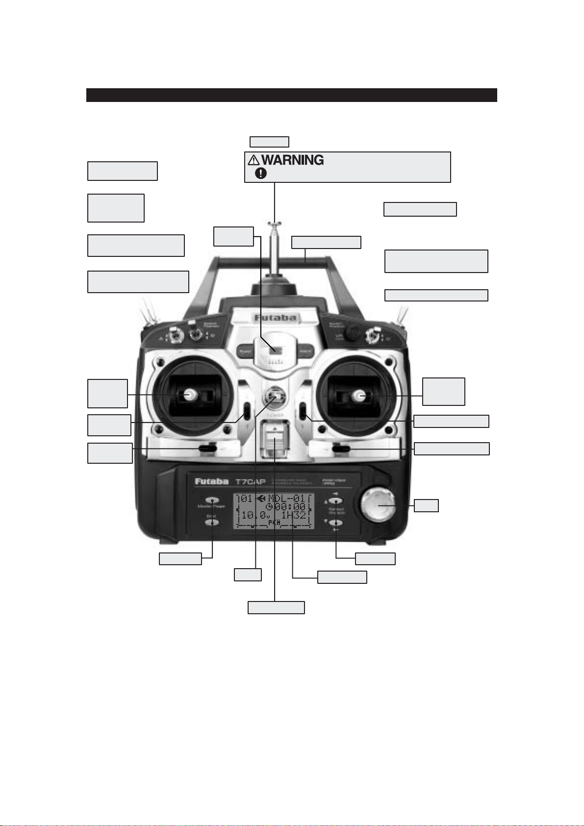
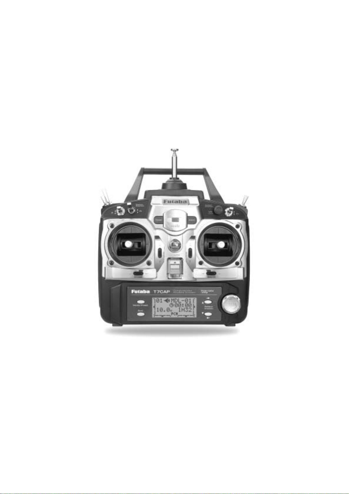
TRANSMITTER CONTROLS - AIRPLANE
SW(F)
Snap Roll or
Trainer Switch
SW(E)
Landing Gear
Switch
/CH5
SW(B)
Rudder Dual Rate Switch
/CH7
SW(A)
Elevator Dual Rate Switch
/TH-CUT/P-MIX/TIMER
Rudder
/Throttle
Stick
Throttle
Trim Lever
Power
LED*
Antenna
Be careful not to bend your antenna when you
collapse or extend it.
Antenna must be fully extended when flying.
VR
Carrying Handle
SW(G)
SW(D)
Flap Trim Control
This controls CH6, and if flaperon mixing
is activated controls the flap.
Elevator - Flap Mixing or
Airbrake Mixing Switch
Aileron Dual Rate Switch
Elevator
/Aileron
Stick
Elevator Trim Lever
Rudder
Trim Lever
Edit Keys
Hook
(for optional neckstrap)
Power Switch
(Up position: ON)
Edit keys
LCD Panel
Aileron Trim Lever
Dial
This figure shows the default switch assignments for a Mode 2 system as supplied by the factory.
You can change many of the switch positions or functions by selecting a new position within
the setting menu for the function you wish to move. (Example: move aileron dual rates to switch G
to create triple rates. See p. 34 for details.)
*Power LED blinks to indicate if any mix switches are activated.
11
Page 12
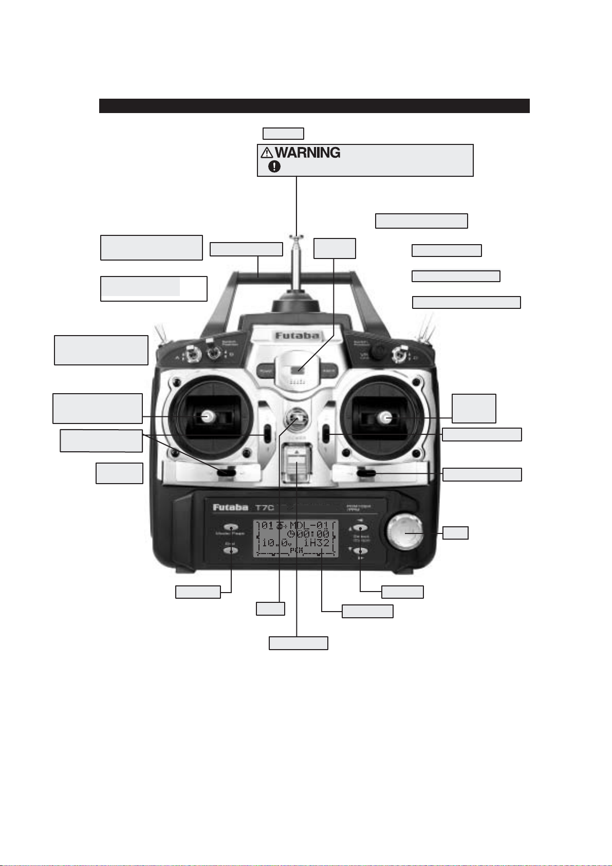
TRANSMITTER CONTROLS - H E L I
SW(B)
Rudder Dual Rate Switch
/CH7
SW(A)
Elevator Dual Rate Switch
/TH-CUT/P-MIX/TIMER
SW(E)
Idle-up 1&2 Switch
/CH5/OFFSET/GYRO
Throttle/Collective
Pitch & Rudder Stick
Throttle/Collective
Trim Lever
Antenna
Carrying Handle
Be careful not to bend your antenna when you
collapse or extend it.
Antenna must be fully extended when flying.
VR
Hovering - Pitch Knob
Power
LED*
SW(H)
Trainer Switch
SW(G)
Throttle - Hold Switch
SW(D)
Aileron Dual Rate Switch
Elevator
/Aileron
Stick
Elevator Trim Lever
Rudder
Trim Lever
Edit Keys
Hook
(for optional neckstrap)
Power Switch
(Up position: ON)
Edit keys
LCD Panel
Aileron Trim Lever
Dial
This figure shows the default switch assignments for a Mode 2 system as supplied by the factory.
You can change many of the switch positions or functions by selecting a new position within
the setting menu for the function you wish to move.
*Power LED blinks to indicate if any mix switches are activated.
12
Page 13

Trainer connector
t
5
Ni-Cd battery pack
Charging jack
Battery connector location
Battery cover
NOTE: If you need to remove or replace the transmitter battery, do not pull on its wires to remove it. Instead,
gently pull on the connector's plastic housing where it plugs into the transmitter.
SWITCH ASSIGNMENT TABLE
The factory default functions activated by the switches and knobs for a Mode 2 transmitter are shown below.
•
Most 7C functions may be reassigned to non-default positions quickly and easily.
•
Basic control assignments of channels 5 & 7 are quickly adjustable in PARA (see p. 28). For example, the channel
•
servo, which defaults to SWITCH E for retract use, can easily be unassigned (NULL)toallowfor easy use as a second
rudder servo in a mix, or to a dial for bomb door or other control.
Note that most functions need to be activated in the programming to operate.
•
Mode 1 transmitter functions are similar but reverse certain switch commands. Always check that you have the desired
•
switch assignment for each function during set up.
Switch/Knob Airplane (AC R O)Helicopter (HELI)
AorHTx.
WITCH A elevator dual rate elevator dual rate
S
Switch B rudder dual rate rudder dual rate
WITCH D aileron dual rate aileron dual rate
S
Switch E
Switch F
WITCH G OR E* idle-up 1 and 2,
S
NOB VR flap/ch 6 HOVERING PIT
K
OR G* landing gear/ch 5 throttle hold
OR H* snap roll/trainer trainer
up = ELE-FLP on
down = AIRBRAKE on
ch5/OFFSET/GYRO
(flap trim if FLAPERONon)
*On the 7CA transmitters, the TOP LEFT SWITCHES are spring-loaded and 3-position; on the 7CH, those switches are on the rightside. For consistency,
he switch positionís designation remains the same (upper left is F, etc), but the functions are moved to match the switch type.
13
Page 14
2
(
C
C
2
3
e
e
m
c
i
b
d
b
r
R
ECEIVER AND SERVO CONNECTIONS
Receiver Aircraft (
Output and
ACRO
)Helicopter (
HELI
)
Channel
1 ailerons/combined right flap & aileron
1
aileron (cyclic roll)
2elevator elevator (cyclic pitch)
3throttle throttle
4 rudder rudder
5 spare/landing gear/combined left flap and aileron
6 spare/ flap(s)/combined left flap and aileron pitch (collective pitch)
7 spare/combined left flap and aileron spare/governor
1
Flaperon mode. (See p. 43).
1,2
1,2
1,2
spare/gyro
Using Second Aileron option, second aileron servo output is sent to channels 5-7toallowuseofa5-channel receiver.
AIL-2) (See p. 43)
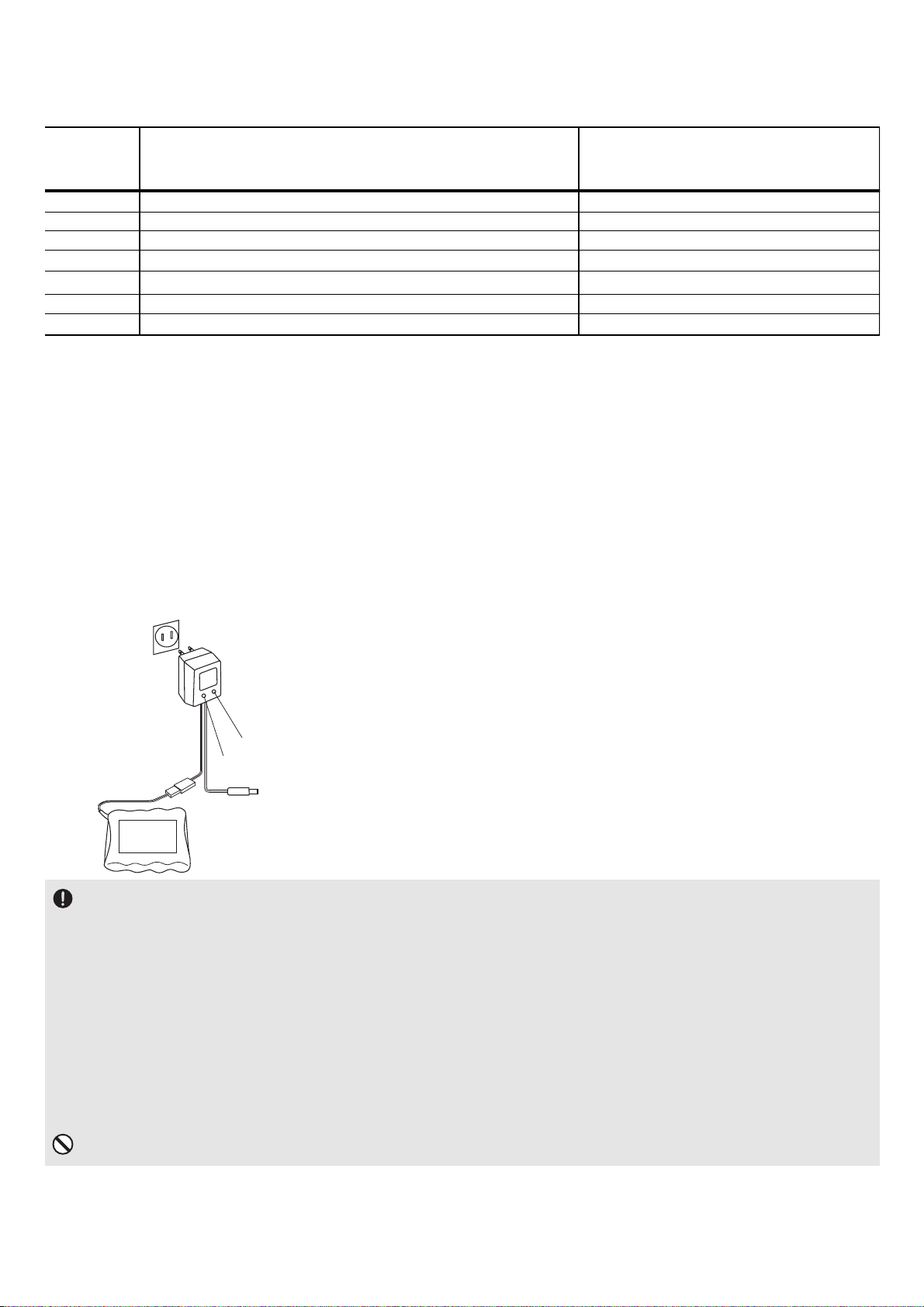
HARGING THE Ni-Cd BATTERIES
harging Your Systemís Batteries
1. Connect the transmitter charging jack and airborne Ni-Cd batteries to the transmitter and receiver connectors of the charger .
. Plug the charger into a wall socket.
. Check that the charger LED lights.
The initial charge, and any charge after a complete discharge,
should be at least 18 hours to ensure full charge. The batteries
Charger
should be left on charge for about 15 hours when recharging the
standard NR-4J, NR4F1500 and NT8S600B Ni-Cd batteries.
TX: Transmitter charging indicato
RX: Receiver charging indicator
To transmitter charging jack
We recommend charging the batteries with the charger
supplied with yoursystem. Note that the useof a fast charger
Receiver Ni-Cd battery
may damage the batteries by overheating and dramatically
reduce their lifetime.
You should fully discharge your system's Ni-Cd batteries periodically to prevent a condition called memory. For
xample, if you only make two flights each session, or you regularly use only a small amount of the batteries' capacity, th
emory effect can reduce the actual capacity even if the batteryis fully charged. You can cycle your batteries with a commercial
ycling unit*, or by leaving the system on and exercising the servos by moving the transmitter sticks until the transmitter shuts
tself off. Cycling should be done every four to eight weeks, even during the winter or periods of long storage. Keep track of the
atteries' capacity during cycling; if there is a noticeable change, you may need to replace the batteries.
*Note that your 7C transmitter system is protected from accidental reverse polarity, power surges and other electrical
amage by a diode. The transmitter battery must be removed from the system to cycle. The battery easily unplugs from the
attery compartment and has a standard J-plug for easy cycling.
DO NOT attempt to charge your 8-cell transmitter pack on the 4-cell receiver plug of the wall charger!
14
Page 15
A
djusting the length of the non-slip control sticks
)
Y
t
b
N
t
N
U
i
W
b
W
Stick tip A Locking piece B
Stick lever tension adjustment
Aileron
Elevator
Youmay change the length of the control sticks to make your transmitter more
comfortable to hold and operate. To lengthen or shorten your transmitterís sticks,
first unlock the stick tip by holding locking piece B and turning stick tip A
counterclockwise. Next, move both pieces up or down (to lengthen or shorten
When the length feels comfortable, lock the position by turning locking
piece B counterclockwise, while holding piece A.
Stick Stick
Rudder
Mode 2 transmitter with rear cover removed.
ou may adjust the tension of your sticks to provide the feel that you prefer for flying.
o remove the rear case of the transmitter. First, remove the battery cover on the rear of the transmitter. Next, unplug the
attery wire and remove the battery from the transmitter.
ext, using a screwdriver, remove the four screws
hat hold the transmitterís rear cover in position, and put them in a safe place. Gently ease off the transmitterís rear cover.
ow you'll see the view shown in the figure above.
sing a small Phillips screwdriver, rotate the adjusting screw for each stick for the desired spring tension. The tension
ncreases when the adjusting screw is turned clockwise.
hen you are satisfied with the spring tensions, reattach the transmitter's rear cover. Check that the upper printed circuit
oard is on its locating pins.
hen the cover is properly in place, reinstall and tighten the four screws. Reinstall the battery cover.
Adjusting Display Contrast
To adjust the display contrast, from the home menu press and hold the End button.
Turn the dial while still holding End button:
clockwise to brighten
counterclockwise to darken the display
Let go off the dial and the button.
To adjust your springs, youíll have
Changing Modes:
Hold down the MODE and End buttons while turning on the transmitter. The screen reads "STK-MD". Change this to
the correct mode. Note that this will NOT change the throttle and elevator rachets, etc. Those are mechanical changes
that must be done by a service center.
15
Page 16

RADIO INSTALLATION
While you are installing the battery, receiver, switch harness and servos into your model's fuselage, please pay attention to
the following guidelines:
Use the supplied rubber grommets when you mount each servo. Be sure not to
over-tighten the screws. If any portion of the servo case directly contacts the fuselage or
the servo rails, the rubber grommets will not dampen the vibration, which can cause
mechanical wear and servo failure.
Servo Throw
Once you have installedthe servos, operate each one over its full travel and check that the pushrod and output
arms do not bind or collide with each other, even at extreme trim settings. Check to see that each control linkage does
not require undue force to move (if you hear a servo buzzing when there is no transmitter control motion, most likely there
is too much friction in the control or pushrod). Even though the servo will tolerate loads, any unnecessary load applied to
the servo arm will drain the battery pack quickly.
Switch Harness Installation
When you are ready to install the switch harness, remove the switch cover and use it as a template to cut screw holes
and a rectangular hole slightly larger than the full stroke of the switch. Choose a switch location on the opposite side of
the fuselage from the engine exhaust pipe, and pick a location where it canít be inadvertently turned on or off during
handling or storage. Install the switch so it moves without restriction and snaps from ON to OFF and vice versa.
Receiver Antenna
It is normal for the receiver antenna to be longer than the fuselage.
DO NOT cut or fold it back on itself --- cutting or folding changes the electrical length of the antenna and may
reduce range. Secure the antenna to the top of the vertical fin, and let the excess wire length trail behind. You may run the
antenna inside of a non-metallic housing within the fuselage, but range may suffer if the antenna is located near metal or
carbon fiber pushrods or cables. Be sure to perform a range check before flying.
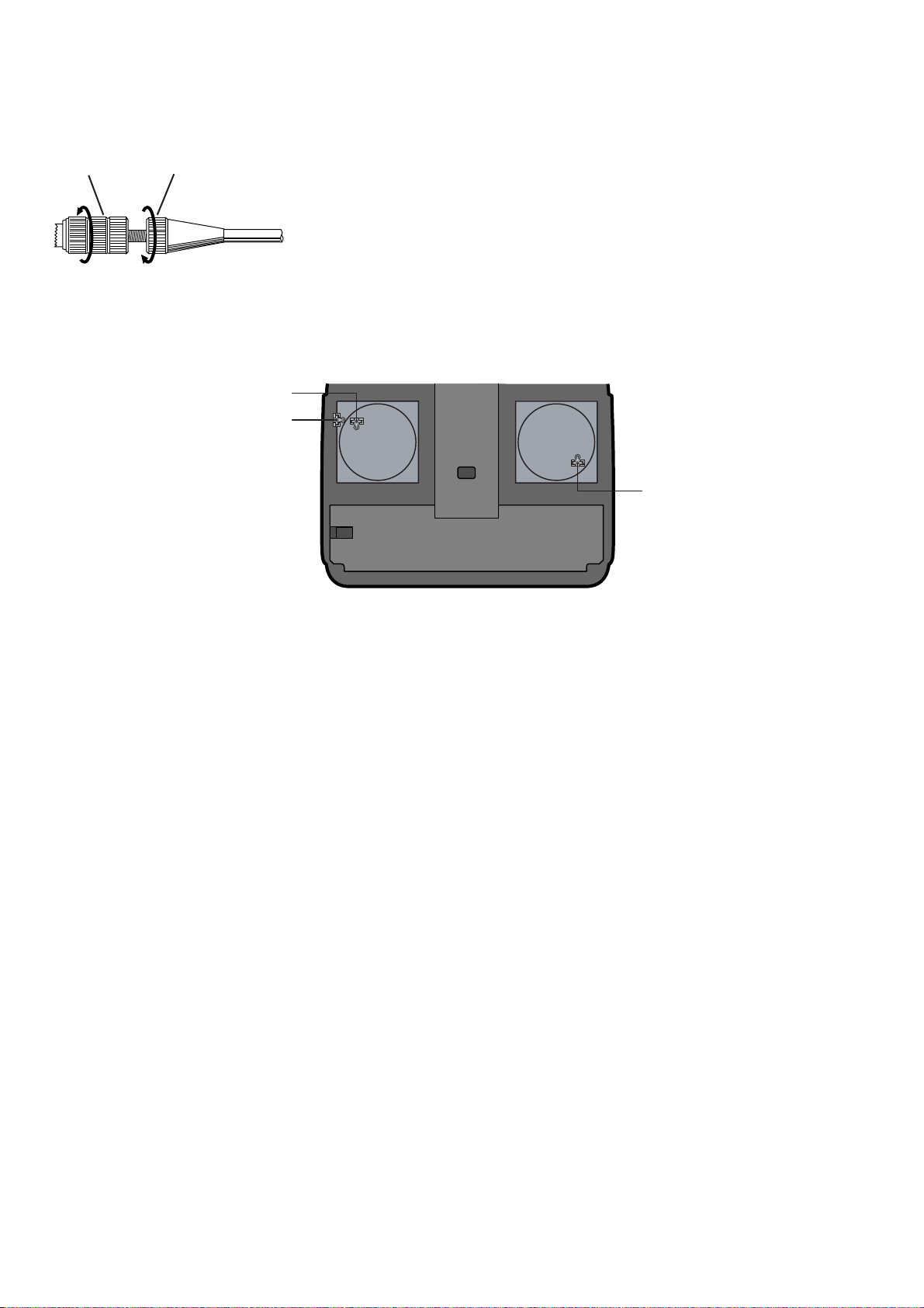
Receiver Notes
When you insert servo, switch or battery connectors into the receiver, note that each plastic housing has an
alignment tab. Be sure the alignment tabis oriented properly before inserting the connector.Toremove a connector
from the receiver, pull on the connector housing rather than the wires.
If youraileron servo(or others)are toofar away toplug intothe receiver, use an aileron extension cord toextend thelength
of the servo lead. Additional Futaba extension cords of varying lengths are available from your hobby dealer . Always use an
extension of the proper length. Avoid plugging multiple extensions togetherto attain your desired length. If distanceis greater than
18" or multiple or high current draw servos are being used, use Futaba Heavy-Duty servo extensions.
Receiver Vibration and Waterproofing
The receiver contains precision electronic parts. Be sure to avoid vibration, shock, and temperature extremes.
For protection, wrap the receiver in foam rubber or other vibration-absorbing materials. It is also a good idea
to waterproof the receiver by placing it in a plastic bag and securing the open end of the bag with a rubber band before
wrapping it with foam rubber. If you accidentally get moisture or fuel inside the receiver, you may experience intermittent
operation or a crash. If in doubt, send the receiver for service.
t
16
Wood screw
Rubber grommet
Brass eyelet
Servo moun
or rail
Page 17

Range Testing Your R/C System
Please note that different systemsdemonstrate differentrange checksand thesame systemwill rangecheck differentlyin different
conditions. Also, the receiver antenna's installation affects the range test -- exiting the top of the model is ideal.
This is a brief explanation of range test. For more in-depth specifics on receiver antenna mounting, additional checks if
unsatisfactory range is demonstrated, range checking with gasoline powered engines, etc, please see our F.A.Q. page a
www .futaba-rc.com.
•
Leave the transmitter's antenna retracted and be sure both batteries are fully charged.
•
Position the aircraft away from wires, other transmitters, etc.
Test one - engine/motor off, minimum of 100 ft. range
•
Have a friend view the model but not hold it, engine off. (People conduct signals, too!)
•
Walk away from the model, working all controls constantly. Stop when the servos jitter significantly (a jitter here and
there is normal), control movement stops (PCM), or you lose control altogether.
•
Measure the distance. If greater than 100 feet, great! Proceed to Test 2. Less than 100 feet of range check means you
need more information to determine if your systemis safe to fly. Please see our web site or call support for additional
tests to perform before flying your system.
•
Repeat with friend holding the model. Note any differences.
Test two - engine/motor on
•
Repeat the test with the model'sengine running and withsomeone holding the model. If a decreaseof more than 10%
is noted, research and resolve the cause of interference prior to flying your model.
What your fully operational system demonstrates is the normal range for your system in those conditions. Before every flying
session, it is critical that you perform a range check. It is also required by the AMA Safety Code. If you notice a significant
decrease in range with fully charged batteries, do not attempt to fly.
Aircraft (fixed wing and helicopter) Frequencies
17
72 MHz band
Ch. MHz Ch. MHz
11 72.010 36 72.510
12 72.030 37 72.530
13 72.050 38 72.550
14 72.070 39 72.570
15 72.090 40 72.590
16 72.110 41 72.610
17 72.130 42 72.630
18 72.150 43 72.650
19 72.170 44 72.670
20 72.190 45 72.690
21 72.210 46 72.710
22 72.230 47 72.730
23 72.250 48 72.750
24 72.270 49 72.770
25 72.290 50 72.790
26 72.310 51 72.810
27 72.330 52 72.830
28 72.350 53 72.850
29 72.370 54 72.870
30 72.390 55 72.890
31 72.410 56 72.910
32 72.430 57 72.930
33 72.450 58 72.950
34 72.470 59 72.970
35 72.490 60 72.990
50 MHz Band (Amateur Radio Operator "HAM" license required)
Ch. MHz Ch. MHz
00 50.800 01 50.820
02 50.840 03 50.860
04 50.880 05 50.900
06 50.920 07 50.940
08 50.960 09 50.980
Installing your frequency number flag:
It is very important that you display your
transmitting channel number at all times. To install your
flag, peeloff the channel number's backingsheet, and carefully
stick the numbers to both sides of the number holder.Now you
can snap the number holder onto the lower portion of the
antenna as shown in the figure --- use the clip that fits more
snugly on your antenna. You may wish to cut off the other,
unused clip on the other side of the flag.
The following frequencies and channel numbers may be used for flying aircraft in the United States:
Page 18

TRANSMITTER DISPLAYS & BUTTONS
When you first turn on your transmitter, a confirmation double beep sounds, and the screen shown below appears. Before
flying, or even starting the engine, be sure that the model type and name appearing on the display matches the model that
you are about to fly! If you are in the wrong model memory, servos may be reversed, and travels and trims will be wrong,
leading to an immediate crash.
Edit buttons and Start-up Screen (appears when system is first turned on):
MODE/PAGE BUTTON: (key)
Press and hold MODE BUTTON for one second to open programming menus. Press MODE BUTTON to switch between
BASIC and ADVANCE menus. HELI only: Press MODE BUTTON to scroll between conditions in certain functions.
END BUTTON:(key)
Press END BUTTON to return to previous screen. Closes functions back to menus, closes menus to start-up screen.
SELECT/CURSOR BUTTONS:(key)
Press SELECT/CURSOR BUTTON to scroll through and select the option to edit within a function.
Press S
ELECT/CURSOR BUTTON to page up/page down within BASIC or ADVANCE menu.
Turn Dial:
Turn D
IAL clockwise or counterclockwise to quickly scroll through functions within each menu.
Turn DIAL clockwise or counterclockwise to scroll through choices within an option of a function (for example, to
select which switch controls dual/triple rates).
Press Dial:
Press DIAL to select the actual function you wish to edit from the menu.
Press DIAL and hold one second to confirm major decisions, such as the decision to: select a different model from
memory, copy one model memory over another, trim reset, store channel position in FailSafe, change model type, reset
entire model. System will ask if you are sure. Press D
IAL again to accept change.
18
Throttle trim
display
Mode
key
End
key
Modulation indicator
(PCM shown)
Model
number
Rudder trim
display
Battery voltage
Model
Aileron trim
name
display
Elevator trim
display
Select
key
Dial
Page 19
WARNING & ERROR DISPLAYS
An alarm or error indication may appear on the display of your transmitter for several reasons, including when the
transmitter power switch is turned on, when the battery voltage is low, and several others. Each display has a unique sound
associated with it, as described below.
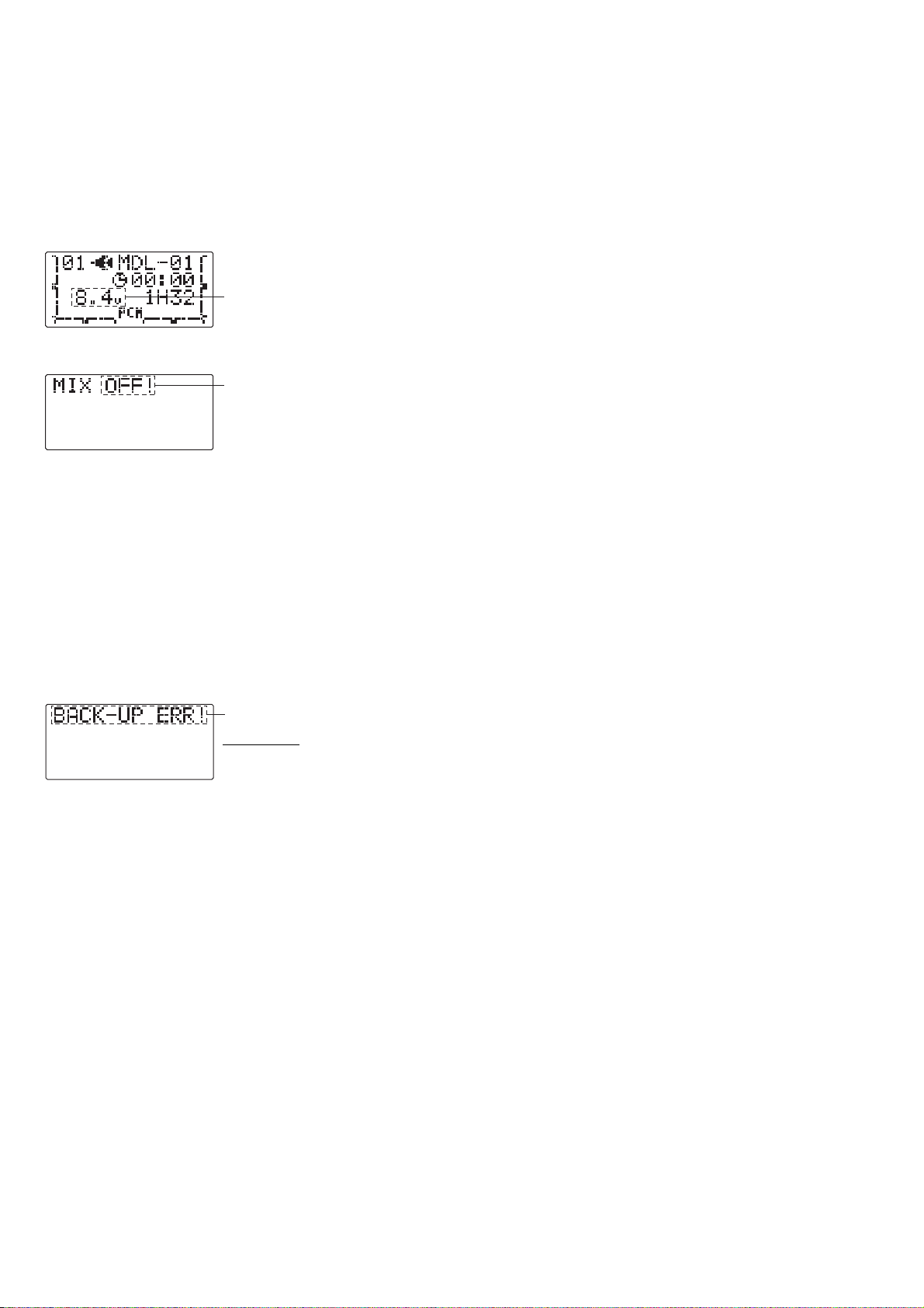
LOW BATTERY ERROR: Warning sound: Continuous beep until transmitter is powered off.
The LOW BATTERY warning is displayed when the transmitter battery voltage drops below 8.5V.
Land your model as soon as possible before loss of control due to a dead battery.
MIXER ALERT WARNING: Warning sound: 5 Beeps (repeated until problem resolved or overridden)
The MIXER ALERT warning is displayed to alert you whenever you turn on the transmitter with any of
mixing switches active. This warning will disappear when the offending switch or control is deactivate
Switches for which warnings will be issued at power-up are listed below:
ACRO: Throttle cut, snap roll, airbrake HELI:Throttle hold, idle-up
If turning a switch OFF does not stop the mixing warning: When the warning does not stop even when the mixing switch
indicated by the warning display on the screen is turned off, the functions described previously probably use the same
switch and the OFF direction setting is reversed. In short, one of the mixings described above is not in the OFF state. In
this case, reset the warning display by pressing both S
ELECT BUTTONS simultaneously. Then change one of the switch
settings of the mixings duplicated at one switch.
BACKUP ERROR: Warning sound: 4 beeps (repeated continuously)
The BACKUP ERROR warning occurs when the transmitter memory is lost for any reason. If this occurs, all of the data will
be reset when the power is turned on again.
Do not fly when this message is displayed -all programming has been erased and is not
available. Return your transmitter to Futaba for service.
19
flash
flash
flash
Page 20

AIRCRAFT (ACRO) MENU FUNCTIONS
Please note that all BASIC menu functions are the same for airplanes (ACRO)andhelicopters (H-1/H-2/HR3/HN3/H-3/HE3
; the helicopter BASIC menu includes additional features(swashplate adjustment and throttle/pitch curves and revofor Norm
20
flight mode) that are discussed in the Helicopter section.
AIRPLANE (ACRO)FUNCTIONS ................20
Map of Functions ...........................21
Quick Guide to Setting up a 4-channel Airplane ....22
ACRO BASICMENU FUNCTIONS ................25
MODEL Submenu: MODEL SEL. , COPY and NAME . .25
Parameter(PARA.) Submenu:
CH5 & CH7
..............................28
RESET,TYPE,MODUL,
Servo REVERSE .............................31
End Point (E. POINT) ........................32
Idle Management: THR-CUT ...................33
Dual Rates and Exponential ( D/R,EXP ) ..........34
TIMER ...................................37
TRAINER ..................................38
TRIM .....................................39
SUB-TRIM .................................40
Fail Safe (F/S).............................41
ACRO ADVANCE MENU FUNCTIONS ............42
Wing types ................................42
(FLAPRN)Flaperon ...................43
(FL-TRIM)Flap Trim ...................44
ELEVON (see tail types) ...................45
Tail types .................................45
ELEVON ................................45
V-TAIL ..................................46
SNAP ROLL................................47
Mixes: definitions and types ...................48
ELE-FLP ................................49
FLP-ELE ..............................50
AIL-RUD .... ..........................51
Air Brake (A.BRAKE) ..... ................52
Prog. Mixes (P-MIX1-3) .................53
Page 21

21
(Startup screen)
Mode/Page Select
End Selection
Cursor Down
Cursor Up
Dial Left
Dial Right
Dial Right or Left
Press Button
Switch Up
Switch at Center
Switch Down
Stick Up
Stick Right
Stick Down
Stick Left
Turn Knob Right
Turn Knob Left
To enter the Basic Menu, press the
ode key for one second.
M
(for one second)
Select
(Cursor)
Select
(Cursor)
Mode/Page
ACRO Basic Menu
(Basic Menu 1)
(Basic Menu 2)
(Basic Menu 3)
End
To return to the Startup screen, press the
End key.
Mode/Page
ACRO
ADVANCE
Press Mode/Page key to toggle back
and forth between BASIC and
ADVANCE menus.
Menu
Press Select/Cursor keys to page up and down through the 3 pages of
screens in each menu.
Turn the Dial clockwise or counterclockwise to
highlight function in Menu screen. Then press the
Dial to choose that function.
Page 22

A QUICK GUIDE: GETTING STARTED WITH A BASIC 4-CHANNEL AIRCRAFT
This guide is intended to help you get acquainted with the radio, to give you ajump start on using your new radio, and togive you
some ideas and direction in how to do even more than you may have already considered. It follows our basic format of all
programming pages: a big picture overview of what we accomplish; a "by name" description of what we're doing to help acquaint
you with the radio; then a step-by-step instruction to leave out the mystery when setting up your model.
For additional details on each function, see that function's section in this manual. The page numbers are indicated in the
goals column as a convenience to you.
See p.21 for a legend of symbols used.
GOALS of EXAMPLE STEPS INPUTS for EXAMPLE
Prepare your aircraft. Install all servos, switches, receivers per your model's instructions.
Turn on transmitter then receiver; adjust all linkages so surfaces are nearly centered.
Mechanically adjust all linkages as close as possible to proper control throws.
Check servo direction.
Make notes now of what you will need to change during programming.
22
Name the model.
P. 25.
[Note that you do not need to do
anything to "save" or store this data.
Only critical changes such as a MODEL
RESET require additional keystrokes to
accept the change.]
Reverse servos as needed for proper
control operation.
P. 31.
Adjust Travels as needed to match
model's recommended throws (usually
listed as high rates). P. 32.
Open the BASIC menu, then open the
MODEL submenu.
Go to MODEL NAME.
Input aircraft's name.
Close the MODEL submenu.
In the BASIC menu, open (servo)
REVERSE.
Choose desired servo and reverse its
direction of travel. (Ex: reversing
rudder servo.)
From BASIC menu, choose END POINT.
Adjust the servo's end points.
(Ex: throttle servo)
Close the function.
Turn on the transmitter.
for 1 second.
(If ADVANCE, again.)
as needed to highlight MODEL.
to choose MODEL.
to NAME.
(First character of model's name is flashed.)
to change first character.
When proper character is displayed,
to move to next character.
Repeat as needed.
to return to BASIC menu.
4steps to REVERSE.
to choose REVERSE.
to CH4: RUDD
so REV is selected.
Repeat as needed.
2steps to END POINT.
to choose END POINT.
to THROTTLE.
T
HROTTLE STICK.
until carb barrel closes as desired.
T
HROTTLE STICK.
until throttle arm just opens carb
fully at full THROTTLE STICK.
Repeat for each channel as needed.
Page 23

With digital trims you don't shut the engine off with THROTTLE TRIM.Let's set up throttle cut (THR-CUT)now.
GOALS of EXAMPLE STEPS INPUTS for EXAMPLE
23
THR-CUTshuts the engine off completely
with the flip of a switch. P . 33.
Set up dual/triple rates and
exponential (D/R,EXP).
P. 34.
(Note that in the middle of
the screen is the name of the
channel AND the switch position you
are adjusting. Two or even THREE
rates may be set per channel by
simply choosing the desired switch
and programming percentages with
the switch in each of its 2 or 3
positions.)
From the BASIC menu, choose THR-CUT.
Activate, assign S
WITCH and adjust.
Close the function.
From the BASIC menu, choose
D/R,EXP.
Choose the desired control, and set the
first (Ex: high) rate throws and
exponential.
to THR-CUT.
to choose THR-CUT.
to OFF.toSW.
to desired switch and position.
(default: A and down position)
to RATE . A to down position.
T
HROTTLE STICK.
until throttle barrel closes
completely.
to D/R,EXP.
to choose D/R,EXP.
A to up position.
to CH> .
to choose CH>2 (elevator).
to D/R .
to set desired percentage.
to EXP.
to set desired percentage.
Page 24

GOALS of EXAMPLE STEPS INPUTS for EXAMPLE
24
Where next?
Set the second (low)rate throws and
exponential.
Optional: change dual rate switch
assignment. Ex: elevator to switch G
(7CA) or E (7CH) with 3 positions.
A to down position.
to D/R.
Repeat steps above to set low rate.
to SW.toG or E.
G or E to center position.
Repeat steps above to set 3rd rate.
(Other functions you may wish to set up for your model.)
TRAINER p. 38.
Multiple wing and/or tail servos: see wing types and tail types, p. 42, 45.
Elevator-to-flap, flap-to-elevator , and other programmable mixes p. 48.
Retractable Gear, Flaps on a Switch, Smoke systems, kill switches,
auxiliary channel (ch5 and ch7) setups. p. 28.
Page 25
A
LOOK AT THE RADIO'S FUNCTIONS STEP BY STEP
M
L
.
G
N
f
c
C
m
MODELsubmenu: includes three functions that manage model memory: MODEL SELECT, MODEL COPY and MODEL NA
Since these functions are all related, and are all basic features used with most models, they are together in the MODE
submenu of the BASIC menu.
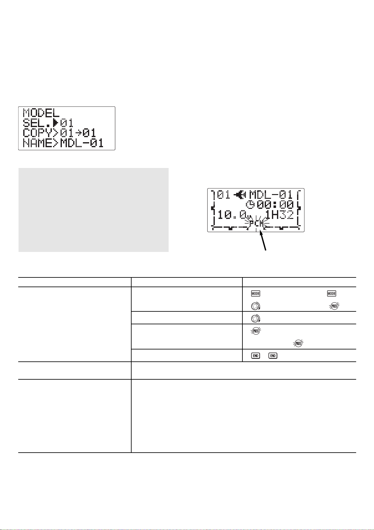
MODEL SELECT: This function selects which of the 10 model memories in the
transmitter to set up or fly.
(Each model memory may be of a different model type from the other memories
NOTE: When you choose a new model in the
MODEL SELECT function, if the new model is set to
the other modulation, you must cycle the transmitter
power to change modulations. If you do not cycle
the power, the modulation type will flash on the
home screen to remind you. You are still
transmitting on the other modulation until you affect
this change.
OAL: STEPS: INPUTS:
Select Model #3.
OTE: This is one of several functions
or which the radio requires
onfirmation to make a change.
onfirm proper modulation of new
odel memory.
Where next?
FLASHING
Open BASIC menu, then open MODEL
submenu.
Choose Model #3.
Confirm your change.
Close.
If PPM or PCM are flashing in the middle of the lower side, then the new model is se
for the other receiver type. Turn the transmitter off/on to change the modulation.
NAME the model: see p. 27.
Change MODEL TYPE (aircraft, heli): see p. 28.
Change modulation [FM (PPM)orPCM]: see p. 28.
Utilize servo REVERSE: see p. 31.
Adjust END POINTs: see p. 32.
Set up TH-CUT for throttle management: see p. 33.
for 1 second.
if required to MODEL.
to 3.
for 1 second.
sure? displays.
(If ADVANCE, again.)
25
Page 26

MODEL COPY: copies the current model data into another model memory in the transmitter.
a
h
E
G
t
C
N
f
c
The number of the model memory you are copying from and into is displayed.
Notes:
Any datainthemodelcopiedto will be written over and lost, including name, type
•
modulation. It cannot be recovered.
With the trainer FUNC mode it is not necessary to have the student radio contain t
•
setup of the aircraft. See TRAINER,p.38.
xamples:
Start a new model that is similar to one you have already programmed.
•
Copy the current model data into another model memory as a backup or before experimenting with new settings.
•
Edit a copy of your modelís data to fly the model in different conditions (i.e. Helicopter using heavier weight blades;
•
airplane model at extreme altitudes).
OAL of EXAMPLE: STEPS: INPUTS:
opy model 3 into model 5.
OTE: This is one of several
unctions for which the radio requires
onfirmation to make a change.
Where next?
*Radio shows progress on screen as the model memory is being copied. Note that if the power switch is turned off prior to completion,
he data will not be copied.
Open the BASIC menu, then open
MODEL submenu.
Confirm you are currently using the
proper model memory. (Ex: 3)
Go to MODEL COPY and choose the
model to copy into.(Ex:5)
Confirm your change.
Close.
SELECT the copy you just made: see p. 25.
Rename it (it is currently named exactly the same as the model copied): see p. 25.
for 1 second.
to MODEL.
If SELECT does not indicate 3,
use MODEL SELECT,p.25.
for 1 second.
sure? displays. *
(If ADVANCE, again.)
to 5.
26
Page 27

MODEL NAME: assigns a name to the current model memory. By giving each model a name that is immediatel
y
r
h
c
N
u
c
a
t
G
N
t
ecognizable, you can easily comfirm the correct model, and minimize the chance of flying the wrong model memorywhic
ould lead to a crash.
OTE:Whenyou COPY one model memory over another, everything is copied, including the model's name. Similarly, if yo
hange MODEL TYPE ordo a MODEL RESET,the entirememory is reset,including MODEL NAME.So the firstthing you will w
odoafter you COPY a model, change its type, or start from scratch, is rename the new copy to avoid confusion.
OAL of EXAMPLE: STEPS: INPUTS:
ame model 3 "CAP-01" (where
he underline represents a blank
space.)
Adjustability and values:
Up to 6 characters long.
•
Each character may be a letter, number, blank, or a symbol.
•
The default names assigned by the factory are in MDL-xx format (MDL-01 for
•
first model memory, etc.)
Open MODEL submenu.
Confirm you are currently using the
proper model memory. (Ex: 3)
Go to NAME and change the first
character. (Ex: M to C)
Choose the next character to change.
for 1 second.
to MODEL.
If SELECTdoes not indicate 3,
perform MODEL SELECT,p.25.
(If ADVANCE, again.)
to C.
Where next?
Repeat the prior steps to complete
naming the model.
Close.
Change the MODEL TYPE to helicopter: see p. 28.
Change the receiver modulation setting from PPM to PCM or vice versa: see p. 28.
Utilize servo REVERSE : see p. 31.
Adjust servo travel with END POINT :seep. 32.
Set up dual/triple rates and exponential (D/R,EXP): see p. 34.
to A
Repeat.
27
Page 28

PARAMETER submenu: sets those parameters you would likely set once, and then not disturb again.
F
y
y
r
T
e
N
a
f
T
G
t
N
f
Once you have selected the correct model you wish to work with, the next step is
setting up the proper parameters for this specific model:
What is the model's type?
•
What type is the receiverís modulation [PPM(FM) or PCM]?
•
If you are utilizing either of the twin aileron functions, do you need to tell the
•
your receiver is only 5 channels?
irst it is important to clear out any old settings in the memory from prior use, using the MODEL RESET.
MODEL RESET: completely resets all data in the individual model you have currently selected. Don't worry - there is no wa
ou can accidentally delete all models in your radio with this function. Only a service center can completely reset your
adio's entire memory at once. To delete each model in your radio's memory (for example when selling), you must SELEC
ach model, reset that memory, then go SELECT the next memory, etc.
ote that when you COPY one model memory into another or change the model's type, you need not delete all existing dat
irst by using this function. COPY completely overwrites anything in the existing model memory, including MODEL NAM
he MODEL TYPE function overwrites all data except name and MODUL.
OAL of EXAMPLE: STEPS: INPUTS:
Reset model memory 1.
OTE: This is one of several
unctions for which the radio requires
confirmation to make a change.
Confirm you are currently using the
proper model memory. (Ex: 1)
Open PARAMETER submenu.
Reset the Memory.
On home screen, check model name
and number on top right. If it is not
correct, use MODEL SELECT,p.25.
for 1 second.
to 3rd page of menu.
to PARAMETER.
for one second.
(If ADVANCE, again.)
Confirm the change.
Close.
Where next?
*Radio shows progress on screen as the model memory is being reset. Note that if the power switch is turned off prior to completion,
he data will not be reset.
Now that the memory is reset, name has returned to the default (Ex: MDL-01).
NAME the model: p. 25.
COPY adifferent model into this memory: p. 25.
SELECT a different model to edit or delete: p. 25.
Change the MODEL TYPE to helicopter: see p. 28.
Change the receiver modulation from FM(PPM)toPCM or vice versa: see p. 28.
Utilize servo REVERSE:seep. 31.
Adjust servo travel with END POINT:seep. 32.
Set up dual/triple rates and exponential (D/R,EXP): see p. 34.
28
sure? displays. *
Page 29

MODEL TYPE: sets the type of programming used for this model.
T
B
ft
(
,
t
I
y
G
m
[
he 7C has 10 model memories, which can each support:
efore doing anything else to set up your aircraft, first you must decide which MODEL TYPE best fits this particular aircra
Each model memory may be set to a different model type.) If your transmitter is a 7CA, the default is ACRO.Ifitisa7CH
he default is H-1.
f you are using a heli
our model setup. Note that changing
MODEL TYPE
one powered aircraft (ACR O)memory type (with multiple wing and tail
•
configurations. See FRAPERON, ELEVON and V-TAIL for further information.);
six helicopter swashplate types, including CCPM. See Helicopter MODEL TYPE
•
for details, p. 61.
, please go to that chapter now to select the proper model type and support
MODEL TYPE
resets all data for the model memory, including its name.
OAL of EXAMPLE: STEPS: INPUTS:
Select the proper MODEL TYPE for your
odel. Ex: ACRO.
NOTE: This is one of several functions
that requir es confirmation to make a
change. Onlycritical changes require
additional keystrokes to accept
the change.]
Open the BASIC menu, then open the
PARAMETER submenu.
Go to MODEL TYPE.
Select proper MODEL TYPE.
Ex: ACRO.
Confirm the change. Close PARAMETER.
Turn on the transmitter.
for 1 second.
then to highlight PARAMETER
to choose PARAMETER.
to TYPE.
to ACRO.for1second.
sure? displays. to confirm.
to return to BASIC menu.
(If ADVANCE, again.)
29
Page 30

Modulation select (MODUL): sets the type of modulation transmitted.
The modulation of your receiver will determine whether you utilize PPM or PCM setting in MODUL during transmission
Note that you have to turn your transmitter off and back on before a modulation change becomes effective. If you choose
PCM,besure you understand and set the FailSafe (F/S) settings as you intended (see p. 41).
PCM = Pulse Code Modulation PPM =Pulse Position Modulation (also called FM).
Adjustability:
•
PCM setting for all Futaba PCM1024 receivers, regardless of number of channels
(ie.R138DP/148DP/149DP, R309DPS);
•
PPM setting for all Futaba compatible (negative shift) FM receivers, regardless of
number of channels (ie. R127DF, R123F, R148DF).
•
Not compatible with PCM512 receivers such as the R128DP and R105iP.
•
Not compatible with other brands of PCM receiver, or positive shift FM receivers
(ie. JR, Airtronics).
GOAL of EXAMPLE: STEPS: INPUTS:
NOTE: When you change models in MODEL SELECT,ifthe
new model is set to the other modulation type, you must
cycle the transmitter power to change modulations. The
modulation will flash on the home screen to remind you
until you do so. See p. 25, MODEL SELECT, for details.
30
Change model 1 from FM (PPM)to
PCM
Where next?
Confirm you are currently using the
proper model memory (Ex: 1)
Open BASIC menu, then open
PARAMETER submenu.
Go to MODUL and change setting.
Close menu and cycle power.
On home screen, check model name and
number on top and the modulation
on bottom. If it is not the correct
model, use MODEL SELECT,p.25.
for 1 second.
(If ADVANCE, again.)
to 3rd page of menu.
to PARAMETER.
to MODUL.toPCM.
PCM flashes on screen
P
OWER OFF.POWER ON.
Now that the model is in the proper modulation, the 7C should communicate
with the receiver. If it does not, confirm the modulation/frequency of the
receiver. [Futaba receivers ending in F use PPM (ex: R127DF), ending in P use
PCM (ex: R149DP)].
Change MODEL TYPE to helicopter: see p. 28.
Set F/S settings for when PCM receiver sees interference: see p. 41.
Utilize servo REVERSE:seep. 31.
Adjust servo travel with END POINT:seep. 32.
Set up dual/triple rates and exponential (D/R,EXP): see p. 34.
Page 31

Servo reversing (REVERSE): changes the direction an individual servo responds to a CONTROL STICKmotion.
For CCPM helicopters, be sure to read the section on SWASH AFR (p. 63) before reversing any servos.
Except with CCPM helicopters, always complete your servo reversing prior
to any
other programming. If you use pre-built ACRO functions that control multiple servo
such asFLAPERON or V-TAIL,itmay be confusing to tell whether the servoneeds to be
reversed or a setting in the function needs to be reversed. See the instructions for each
specialized function for further details.
Always check servo direction prior to every flight as an additional precaution to confirm proper model memory,
hook ups, and radio function.
NOTE: THR-REV is a special function that reverses the entire throttle control, including moving the trim functionality to the
Stick's upper half. To use THR-REV,turn off the transmitter, hold down the MODE and END keys, turn on. CURSOR DOWN to
THR-REV and turn the DIAL to REV.Turn the transmitter off and back on. This change affects all models in the radio.
GOAL of EXAMPLE: STEPS: INPUTS:
31
Reverse the direction of the elevator
servo.
Where next?
Open REVERSE function.
Choose proper channel and set
direction. (Ex: ELE REV)
Close.
for 1 second.
(If ADVANCE, again.)
to REVERSE.
to ELE.
to REV.
Adjust servo travel with END POINT:seep. 32.
Set up dual/triple rates and exponential (D/R,EXP): see p. 34.
Set up flight timers: see p. 37.
Set up trainer functions: see p. 38.
uxiliary channel function (CH5 and CH7): defines the relationship between the transmitter
ontrols and the receiver output for channels 5 and 7.
Adjustability:
channels 5 and 7 may be assigned to any SWITCH (A-H)ornone (null).
•
(for example, moving flaps to a switch)
multiple channels may be assigned to the same switch.
•
channels set to "NULL" are only controlled by mixes.
•
(Ex: utilizing 2 channels for 2 rudder servos. See mixes, p. 53.)
Remember that if you assign primary control of a channel to a switch which you later use for other functions (like
ual/triple rates or airbrakes), every time you use that other function you will also be moving the auxiliary channel.
Page 32

Adjustability:
•
Can set each direction independently.
•
Ranges from 0% (no servo movement at all) to 140%. At a 100% setting, the throw o
the servo is approximately 40º for channels 1-4 and approximately 55º for channels 5
•
Reducing the percentage settings reduces the total servo throw in that direction.
Adjust the throttle high end to avoid binding at the carburetor, and low end to allow for proper carburetor closure.
Adjust flap so up travel is only sufficient for straight and level flight trimming, with full down travel.
END POINT may be adjusted to 0 to keep a servo from moving one direction, such as flaps not intended to also operate
as spoilers.
Retract servos are not proportional. Changing END POINT will not adjust the servo.
end point (and moving the linkage) = torque, accuracy, but transit time to get there.
end point (instead of adjusting linkages) = travel time, but torque, accuracy.
32
Open END POINT function.
Choose proper channel and set
direction. (Ex: flap up 5%)
Close.
for 1 second.
(If ADVANCE, again.)
to END POINT.
to flap.
flap control [default is V
R ].
to 5%.*
V
R(A).to85%.
Move auxiliary channels 5 or 7 to different switch(es): see p. 28.
Set up THR-CUT to cut the engine: see p. 33.
Set up dual/triple rates and exponential (D/R,EXP): see p. 34.
Set up flight timers: see p. 37.
Set up trainer functions: see p. 38.
Set up twin aileron servos: see p. 43.
Page 33

33
Engine idle management: THR-CUT: functions which work with the digital THROTTLE TRIM to provide a simple,
consistent means of engine operation. No more fussing with getting trim in just the right spot for landings!
OAL of EXAMPLE: STEPS: INPUTS:
ecrease the throttle setting (at idle) to
pthe engine with the flip of a switch.
Open BASIC menu, then open
THR-CUT function.
for 1 second.
(If ADVANCE, again.)
to THR-CUT.
efault: SWITCH A in the down
osition)
Activate the function. Choose desired
switch, and the position which
activates the function.
to ON(OFF).
to SW.
to select the desired
switch and position.
With T
HROTTLE STICK at idle, adjust the
A to down position.
rate until the engine consistently shuts
off but throttle linkage is not binding.*
THROTTLE STICK.
here next?
to RATE. until shuts off.
Close.
Set up dual/triple rates and exponential (D/R,EXP): see p. 34.
Set up TRAINER functions: see p. 38.
Set up twin aileron servos: see p. 43.
Page 34

Dual/Triple Rates: reduce/increase the servo travel by flipping a switch,
or (ACRO )they can be engaged by any stick position. Dual rates affect the control
listed, such as aileron, not just a single (ex: channel 1) servo. For example, adjus
aileron dual rate will affect both aileron servos when using FLAPERON, ELEVON, and
aCCPM helicopter.
•
Any SWITCH, A-H.Ifyou choose a 3-position switch, then that dual rate instantly becomes a triple rate (see example).
•
Stick position (ACRO ). (Ex: On rudder you normally use only the center 3/4 of the stick movement except
for extreme maneuvers such as snaps/spins/stalls. As long as your RUDDER STICK does not exceed 90% of maximum
throw, the rudder responds at your lower rate, allowing small, gentle corrections. When the stick passes 90% (ie. stall
turn), the rudder goes to high rate's 90%, which is a MUCH higher amount of travel than your low rate at 89%.)
Ex: EPA = 1" Low Rate = 50% High Rate = 100%
At 89% Low Rate = .45"
At 90% High Rate = .9"
Adjustability:
•
Range: 0 - 140% (0 setting would deactivate the control completely .)
Initial value=100%
•
Having made no changes yet in the D/R,EXP screen, move S
WITCH D to "down" (toward the AILERON STICK
).
•
Cursor down to EXP and dial to 100%.
•
Move SWITCH D up. Hold the AILERON STICK at 1/4 stick and move SWITCH D down.
•
Notice how much less travel there is.
•
Go to 3/4 stick and repeat. Notice how the travel is much closer, if not identical.
34
100% 100%
90% 90%0%
High R ate
Low Rate
High R ate
High R ateLow Rate
100%30%0%
Page 35

•
More sensitive around neutral. (positive exponential, see example)
•
Less sensitive around neutral. (negative exponential, see example)
35
Open D/R,EXP.
Choose channel and switch position.
Set rate and exponential (Ex: high rate
= 95%, 0% exponential.)
Go to 2
nd
switch position and set rate
and exponential.
Optional: if usinga3position switch,
set 3rdrate.
for 1 second.
(If ADVANCE, again.)
to D/R,EXP.
to desired channel.
to 95%.
Confirm 0% EXP.
Repeat above.
Repeat above.
Page 36

36
Open D/R,EXP function.
Choose the channel to change
(Ex: aileron is already selected)
Optional: change switch assignment.
Confirm switch is in desired position
and set rate. (Ex: up = high rate, 75%).
Move S
WITCH to 2nd rate position and
set this particular rate.
(Ex: center = low rate, 25%).
Optional: if using a 3 position
SWITCH, move SWITCH to 3rd position
and set this rate (Ex: down = 3D rate,
140%).
Optional: instead of using a switch,
you can set high rates to be triggered
when the stick moves past a certain
point. To test this, set aileron high
rate to 25%.
Move
AILERON STICK
and notice the huge jump in travel
after the stick moves 90% of its
distance.
to the right
Set each rate's EXP.
(Ex: 0%, +15%, -40%)
Close.
for 1 second.
(If ADVANCE, again.)
to D/R,EXP.
to desired channel.
to G.
G to up position.
G to center position.
G to down position.
You may also change the trigger point
by holding the stick at the desired point,
then pressing and holding the
DIAL.
G to up position.
confirm EXP reads 0.
G to down position.
G to center position.
Set up flight timers: see p. 37.
Set up TRAINER functions: see p. 38.
Adjust the sensitivity of the trims: see p. 39.
Set up twin aileron servos: see p. 43.
Set up programmable mixes to meet your specific needs: see p. 53.
Repeat above steps for elevator and rudder.
to 75%
to 25%
to 140%
to 1.
to 25%
to 15%
to -40%
Page 37

Count down timer: starts from the chosen time, displays time remaining. If the time is exceeded, it continues to count
below 0.
Count up timer: starts at 0 and displays the elapsed time up to 99 minutes 59 seconds.
Independent to each model, and automatically updates with model change.
In either TIMER mode, the timer beeps once each minute. During the last twenty seconds, there's a beep each two seconds.
During the last ten seconds, there's a beep each second. A long tone is emitted when the time selected is reached.
To Reset, choose the desired timer with the SELECT key (while at the startup screen), then press and hold DIAL for 1 second.
Activation by either direction of SWITCH A-H,bySTICK (1-4) . THROTTLE STICK is convenient if you are keeping track of
fuel remaining, or for an electric, how much battery is left.
37
Open BASIC menu, then
open TIMER function.
Adjust time to 4 min. 30 sec., count down.
Activate the function.
Assign to T
HROTTLE STICK and set
trigger point (if timer is to trigger
BELOW this throttle point, so
arrow points down).
Close.
for 1 second.
(If ADVANCE, again.)
to page 3.
to TIMER.
to 4. to 30.
to SW.
to 3(arrow points up).
T
HROTTLE STICK to desired
position (Ex: 1/4 stick).
for 1 second to set.
Adjust END POINTsafter first flight test: see p. 32.
Adjust auxiliary channel assignments: see p. 28.
Set up TRAINER functions: see p. 38.
Page 38

Adjustability:
•
"N": When the TRAINER SWITCH is ON, the channel set to this mode can be
controlled by the student. The set channel is controlled according to any
programming set at the student's
transmitter.
•
"F": When the TRAINER SWITCH is ON, the channel set to this mode can be control
by the student, controlled according to any mixing set attheinstructor's transmitter.
"-": The channel set to this mode cannot be controlled by the student even when the TRAINER SWITCH is ON. The set
channel is controlled by the instructor only, even when the TRAINER SWITCH is ON.
SWITCH: controlled by spring-loaded SWITCH F (7CA) or H (7CH) only. Not assignable.
Compatibility: The 7C may be master or student with any Futaba FM transmitter compatible with the cord. Simply
plug the optional trainer cord (For 7C series, sold separately) into the trainer connection on each transmitter, and
follow the guidelines below.
When throttle/collective are set to "F", 5-channel helicopter practice is possible with a 4-channel transmitter.
Set up the model in a second transmitter, use "N" mode to quickly and safely check proper operation of all
functions, then allow the student radio to fully fly the model.
Using "N" mode, set lower throws, different exponentials, even different auxiliary channel settings on the student
radio (if it has these features).
To ease the learning curve, elevator and aileron may be set to the "N" or "F" mode, with the other channels set to
"-" and controlled by the instructor.
Precautions:
NEVER turn on the student transmitter power.
ALWAYS set the student transmitter modulation mode to PPM.
BE SURE that the student and instructor transmitters have identical trim settings and control motions. Verify by
switching back and forth while moving the control sticks.
FULLY extend the instructor's antenna. Collapse the student's antenna.
Always remove the student transmitter's RF module (if it is a module-type transmitter).
When the TRAINER function is active, the snap roll function is deactivated. Other functions, such as THR-CUT,
which have been assigned to the same switch, are notdeactivated. Always double check your function assignments
prior to utilizing the TRAINER function.
When you select a different model, the TRAINER function is deactivated in the current model for safety reasons.
38
Turn on the TRAINER system and set
up so student has: fully functional
control of aileron to
support
FLAPERON ;
normal control of rudder to allow
lowered travel; and no throttle
channel control (with the instructor
for safety).
Where next?
Open BASIC menu, then open
TRAINER function.
Activate TRAINER.
Choose desired channel(s) and proper
training type(s).
Close.
for 1 second.
(If ADVANCE, again.)
to page 2. to TRAINER.
to OFF.
past AIL and ELE (default OK).
to THR,
to RUD,
to "-": OFF.
TEST student radio function fully prior to attempting to fly!
Set student 7C to PPM (required regar dless of receiver's modulation): see p. 28.
Set up dual/triple rates and exponential (D/R,EXP)onstudent 7C: see p. 34.
Reset trims on student 7C: see p. 39.
to "N": NORM.
Page 39

The 7CA has digital trims which are different from conventional mechanical trim slid
Each T
RIM LEVER is actually a two-direction switch. Each time the TRIM LEVER
pressed, the trim is changed a selected amount. When you hold the TRIM LEVER, the t
speed increases. The current trim position is graphically displayed on the start up scre
The TRIM submenu includes two functions that are used to manage the trim options.
39
Reset trims to neutral after having
adjusted all linkages.
NOTE: This is one of several
functions for which the radio requires
confirmation to make a change.
Where next?
Open BASIC menu, then open
TRIM submenu.
Request and confirm the reset.
Close.
for 1 second.
(If ADVANCE, again.)
to TRIM.
for 1 second.
Beep sounds.
Adjust SUB-TRIMs: see p. 40.
Adjust trim rate (STEP): see below.
Adjust END POINTs: see p. 32.
Set up dual/triple rates and exponential (D/R,EXP): see p. 34.
Double the sensitivity (larger step) of
the AILERON TRIM LEVERS for a first
flight of an aerobatic model to ensure
sufficient range to trim the model for
level flight.
Where next?
Open TRIM submenu and choose the
STEP you wish to change. (Ex: aileron)
Adjust the size ofthe step.(Ex: incr .to 8)
Repeat as desired for other channels.
Close.
for 1 second.
(If ADVANCE, again.)
to TRIM.
to 8.
to ELEV.tonew setting.
Repeat as needed.
Adjust sub trims: see p. 40.
Adjust END POINTs: see p. 32.
Set up dual/triple rates and exponential (D/R,EXP): see p. 34.
.
Page 40

measure and record the desired surface position;
zero out both the trims (TRIM RESETmenu) and the SUB-TRIMs (this menu);
mount servo arms and linkages so that the control surfaceís neutral is as correct as possible; and
use a small amount of SUB-TRIM to make fine corrections.
We recommend that you center the digital trims before making SUB-TRIM
changes, and that you try to keep all of the SUB-TRIM values as small as
possible. Otherwise, when the SUB-TRIMs are large values, the servo's
range of travel is restricted on one side.
40
Open BASIC menu, then open
SUB-TRIM.
Choose the channel to adjust, and
adjust until surfaces match. (Ex: flap)
Repeat for other channels.
Close.
for 1 second.
(If ADVANCE, again.)
to SUB-TRIM.
as needed. to each channel,
as needed.
Adjust trim steps: see p. 39.
Adjust END POINTs: see p. 32.
Set up dual/triple rates and exponential (D/R,EXP): see p. 34.
Page 41

FailSafe (F/S ): instructs a PCM receiver what to do in the event radio interference is recei
Adjustability:
•
Each channel may be set independently.
•
The NOR (normal) setting holds the servo in its last commanded position.
•
The F/S (FailSafe) function moves each servo to a predetermined position.
•
NOTE: the setting of the throttle's F/S also applies to the Battery F/S (see below
The F/S setting is used in certain competitions to spin the aircraft to the ground prior to flying away and doing potential damage
elsewhere. Conversely , may also be used to go to neutral on all servos, hopefully keeping the plane flying as long as possible.
Competition modelers often maintain the NOR function so that brief interferencewill not affect their model's maneuver.
Set the throttle channel so that the engine idles when there is interference (ACRO). This may give enough time to fly away
from and recover from the radio interference and minimize damage if crashed.
For helicopters, NOR is typically the safest choice.
We also recommend setting a gasoline engine's electronic kill switch to the OFFposition in the F/S function for safety reasons.
NOR F/S setting for throttle results in Battery F/S going to the servo position reached by moving THROTTLE STICK to the
bottom with T
RIM LEVER centered;
POS F/S setting for throttle results in Battery F/S also going to the same throttle servo position as the regular F/S .
If using a 6V (5-cell) receiver battery, it is very likely that your battery will be rapidly running out of charge before
41
Change the receiver FailSafe command
for channel 7 (gasoline engine kill
switch) to a preset position.
NOTE: This is one of several functions
for which the radio requir es
confirmation to make a change.
Where next?
Open the BASIC menu, then open
F/S function.
Choose Channel to change. (ex: Ch. 8)
Set and confirm fail safe command.
Repeat as desired.
Close.
for 1 second.
(If ADVANCE, again.)
to F/S .
to Ch 7.
that controls channel 7 to desired
OFFposition.
for 1 second to store.
Wait two minutes and confirm F/S settings as described above.
Read below for information on Battery FailSafe.
Adjust END POINTstogain proper F/S responses if needed: see p. 32.
Adjust SUB-TRIM to gain proper F/S responses if needed: see p. 40.
Page 42

CROADVANCE MENU FUNCTIONS:
ircraft wing types (ACR O):
here are 3 basic wing types in aircraft models:
Simple. Model uses one aileron servo (or multiple servos on a Y-harness into a single receiver channel) and has a tail.
This is the default setup and requires no specialized wing programming.
Twin Aileron Servos. Model uses 2 aileron servos and has a tail. see Twin Aileron Servos.
Tail-less model (flying wing). Model uses 2 wing servos working together to create both roll and pitch control.
see ELEVON.
Twin Aileron Servos (with a tail) (ACR O): Many current generation models use two aileron servos, plugged into two
separate receiver channels. (If your model is a flying wing without separate elevators, see ELEVON,p.45.)
enefits:
Ability to adjust each servo's center and end points for perfectly matched travel.
Redundancy, for example in case of a servo failure or mid-air collision.
Ease of assembly and more torque per surface by not requiring torque rods for a single servo to drive 2 surfaces.
Having more up aileron travel than down travel for straighter rolls ñ aileron differential. (see glossary for definition.)
Using the two ailerons not only as ailerons but also as flaps, in which case they are called flaperons.
Options:
5-channel receiver? Set up AIL-2 (see p. 43) in FLAPERON.
FLAPERON:
Uses CH6 for the second servo (see AIL-2 to use CH5 orCH7.)
Allows flap action as well as aileron action from the ailerons.
Provides FLAP-TRIM function to adjust the neutral point of the flaperons for level flight.
Also allows aileron differential in its own programming.
OTE: Only one of the two wing-type functions (FLAPERON,andELEVON) can be used at a time. Both functions
annot be activated simultaneously. To activate a different wing type, the first must be deactivated.
OAL of EXAMPLE: STEPS: INPUTS:
e-activate FLAPERON so that
Open the FLAPERON function.
for 1 second.
(If basic, again.)
ELEVON can be activated.
to FLAPERON.
De-activate the function.
to INH.
Close function.
Where next?
Set up ELEVON(see p. 45).
42
Page 43

The FLAPERON mixing function uses one servo on each of the two ailerons, and uses them
for both aileron and flap function. For flap effect, the ailerons raise/lower simultaneously
Of course, aileron function (moving in opposite directions) is also performed.
feature is also available (see
FLAP-TRIM)toadjust both neutral positions togeth
for straight-and-level flight or slight increases/decreases of the flap angle.
*Ifyou activate FLAPERON function, you must deactivate ELEVON.seep. 42.
43
Open the FLAPERON function.
Activate the function.
Optional: adjust the aileron
differential.(Ex: +10%)
Optional: If usinga5channel
receiver, change AIL-2 from CH6
to CH5.
Close menu.
for 1 second.
(If basic,again.)
to FLAPERON.
*
to +10%.
to CH5.
Set FLAP-TRIM:seep.44.
Set up AIRBRAKE mix: see p. 52.
View additional model setups on the internet: www.futaba-rc.com/faq/faq-7c.html
Second aileron (AIL-2) : changes the default choice for dual aileron servos from channels 6 to channels 5or7.
This allows you to employ the FLAPERON function while utilizing a 5-channel receiver.
Page 44

FLAP-TRIM allows trimming in flight of the flap action of flaperons.
Most modelers use AIRBRAKE,orprogrammable mixes, to move the flaps to a specified
position via movement of a switch.
44
Add FLAP-TRIM to allow the model's
ailerons to be trimmed together as
flaps at any time during the flight,
with a maximum travel of 5% of the
total flap travel set in FLAPERON.
Where next?
Open the FLAP-TRIM function.
Adjust the travel available to the
flaperons when turning the CH6 DIAL.
(Ex: 5%).
Optional: Set offset, if needed.
Close menu.
for 1 second.
(If basic, again.)
to FLAP-TRIM.
Adjust individual servo's SUB-TRIMs: see p. 40 and END POINTs: see p. 32.
Set up AIRBRAKE mix: see p. 52 and ELEV-FLAP mix: see p. 49.
View additional model setups on the internet: www.futaba-rc.com\faq\faq-7c.html.
Flaperon control; VR)
The function is automatically activated withFLAPERON.
VR to 5%.
VR to 5%.
VR to desired point.
for 1 second to set.
Page 45

Simple. Model uses one elevator servo and one rudder servo (or multiple servos on a Y-harness). This is the default.
Tail-less model. Model uses 2 wing servos together to create roll and pitch control. see ELEVON.seep. 45.
V-TAIL.Model uses 2 surfaces, at an angle, together to create yaw and pitch control. see V-TAIL.seep. 46.
: Only one of the two tail-type functions ( V-TAIL,andELEVON) can be used at a time. The radio provides
(See the wing type example on page 42.)
Adjustability:
• Requires use of CH1 and CH2.
• Independently adjustable aileron/elevator travel.
• Adjustable aileron differential.
You must deactivate the last function to activate ELEVON.
ILERON and ELEVATOR STICKS are moved at the same time the controls may bind or run out of travel.
45
Activate ELEVON.
Adjust aileron differential to +10%.
Where next?
Open the ELEVON function.
Activate the function.
Optional: adjust the aileron
differential.
(Ex: +10%. )
Optional: adjust the aileron/elevator
travel as desired.
Close menu.
for 1 second.
(If basic, again.)
to ELEVON.
to +10%.
Adjust individual servo's SUB-TRIMs: see p. 40 and END POINTs: see p. 32.
Set up dual/triple rates and exponential (D/R,EXP) :seep. 34.
View additional model setups on the internet: www.futaba-rc.com\faq\faq-7c.html
(Elevator travel)
(Aileron travel)
Page 46

V-TAIL mixing is used with v-tail aircraft so that both elevator and rudder function
are combined for the two tail surfaces. The elevator and rudder travel can be
adjusted independently.
Requires use of CH2 and CH4.
Independently adjustable elevator/rudder travels.
CH (2/1 CH): This allows you to utilize V-TAIL function with v-tail aircraft so that elevator and aileron are combined
46
Open the V-TAIL function.
Activate the function.
optional: adjust the travels separately
as desired.
optional: change the channel from
4to1.(If needed.)
Close menu.
for 1 second.
(If basic, again.)
to V-TAIL.
(Elevator travel)
Adjust END POINTs: see p.32andSUB-TRIMs: see p. 40.
Set up dual/triple rates and exponential (D/R,EXP) :seep. 34.
Set up ELEV-FLAP mix: see p. 49.
View additional model setups on the internet: www.futaba-rc.com\faq\faq-7c.html.
(Rudder travel)
to 2/1CH.
Page 47

This function allows you to execute snap rolls by flipping a switch, providing the
same input every time. It also removes the need to change dual rates on the 3
channels prior to performing a snap, as SNAP-ROLL always takes the servos to the
same position, regardless of dual rates, inputs held during the snap, etc.
Note: Every aircraft snaps differently due to its C.G., control throws, moments, etc.
Some models snap without aileron; others snap on elevator alone. Most models snap
most precisely with a combination of all 3 surfaces. Additionally, rate of speed and
acceleration when using the snap switch will affect how the model snaps. For
information on using gyros with airplanes for cleaner precision maneuvers, such as
snaps and spins without over rotation, see p. 56.
Travel: Adjust the amount and direction of elevator , aileron and rudder travel.
Range: -120 to +120 on all 3 channels. Default is 100% of range of all 3 channels.
Directions: (up/right, down/right, up/left, down/left).
This snap-roll function is fully adjustable regarding travels and direction on each of the 3 channels.
AIL ELE RUD
Right positive(up) + + +
Right negative(down) + - Left positive(up) - + Left negative(down) - - +
47
OAL of EXAMPLE: STEPS: INPUTS:
ctivate SNAP-ROLL. Adjust elevator
Open the SNAP-ROLL function.
ravel to 55%, rudder travel to 120% in
he right/up snap.
Activate the function.
Adjust the travels as needed. (Ex:
elevator to +55%, rudder to +120%.)
here next?
Close menu.
Set up programmable mixes: see p. 53.
View additional setups on the internet: www.futaba-rc.com\faq\faq-7c.html.
for 1 second.
to SNAP-ROLL.
to OFFor ON.
to +55%.
to +120%.
(If basic, again.)
Page 48

using 100% of the slave channel's range to do so. An example is FLAPERON. When aileron stick is moved, the flap
servo is told to move exactly the same amount. A 50% linear mix would tell the slave servo, for example, to move to
50% of its range when the master's control is moved 100%.
servo is moved a set percent of its range. An example of this is AIRBRAKE --- moving flaps, flaperons, and elevator all
to a set position at the flip of a switch. (see p. 52.)
stick (works in conjunction with dual rate, a linear mix that adjusts the total range). see D/R,EXP,p.34.
idle an additional set percentage to help close the carburetor. See p. 33.
model loop even tighter than it can on elevator alone. (see p. 49.)
48
Page 49

ELEV-FLAP mixing is the first pre-programmed mix we'll cover. This mix makes
flaps drop or rise whenever the ELEVATOR STICK is moved. It is most commonly u
to make tighter pylon turns or squarer corners in maneuvers. In most cases, the fl
droop (are lowered) when up elevator is commanded.
Rate: -100% (full up flap) to +100 (full down flap), with a default of +50% (one-half of the flap range is achieved
when the ELEVATOR STICK is pulled to provide full up elevator.)
Switch: assignable, or null, so mix is always active.
49
Open the ELEV-FLAP function.
Activate the function.
Adjust the travels as needed.
(Ex: +45%)
Optional: change SWITCH control. Ex:
change to NULL so flaps only respond
to ELEVATOR STICK input.
Close menu.
for 1 second.
(If basic, again.)
to ELEV-FLAP.
to 45%.
to NULL. (--)
Adjust flaperons' flap travel available ( FLAPERON): see p. 43.
Set up AIRBRAKE: see p. 52.
Set up programmable mixes (ex: FLAP-ELEVATOR): see p. 50.
View additional setups on the internet: www.futaba-rc.com\faq\faq-7c.html.
Page 50

FLAP-ELEV mixing is a pre-programmed linear mix. This mix makes the elevator
lower whenever the flaps are lowered. It is used to compensate pitching with flap
Rate: -100% (full up elevator) to +100 (full down elevator), with a default of +50% (one-half of the elevator range is
achieved when the flaps are lowered to full range.)
Offset: offsets the elevator's center relative to the flaps.
Open the FLAP-ELEV function.
Activate the function.
Adjust the travels as needed.
(Ex: +45%)
Close menu.
for 1 second.
(If basic, again.)
to FLAP-ELEV.
to 45%.
View additional setups on the internet: www.futaba-rc.com\faq\faq-7c.html.
50
Page 51

AILE-RUDD mixing is a pre-programmed linear mix. This mix is used to mix
rudder operation with aileron operation automatically, to make realistic
coordinated turns. It is especially effective when turning and banking scale
models or large models that resemble full-sized aircraft.
Rate: -100% to +100, with a default of +50% (one-half of the rudder range is achieved when the A
ILERON STICK is
pulled to provide full left or right aileron.)
51
Open the AILE-RUDD function.
Activate the function.
Adjust the travels as needed.
(Ex: +45%)
Close menu.
for 1 second.
(If basic, again.)
to AILE-RUDD.
to 45%.
View additional setups on the internet: www.futaba-rc.com\faq\faq-7c.html.
Page 52
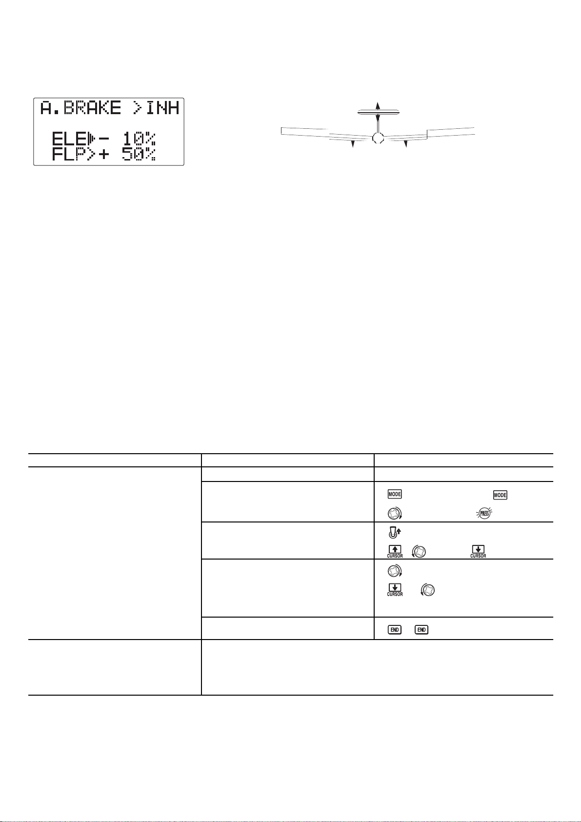
Activation:set positions by flipping SWITCH G.
Provides AIRBRAKE response immediately upon switch movement, going to a pre-set travel on each active channel
without any means of in-flight adjustment.
Channels controlled: Elevator and flap may be set independently in AIRBRAKE ,including set to 0 to have no effect.
52
OAL of EXAMPLE: STEPS: INPUTS:
ctivate AIRBRAKE on a FLAPERON
odel. Adjust the flap travel to 50%,
ith negative elevator (push) of 10%.
Confirm FLAPERON is active.
Open the AIRBRAKE function.
see FLAPERON instructions.
for 1 second.
(If basic, again.)
to AIRBRAKE.
here next?
Activate the function.
Switch C in up position.
to OFF.
Adjust the travels as needed. (Ex:
to -10%.
Flap 50%,Elevator -10%.)
to 50%.
Close menu.
Adjust flaperons' total flap travel available (FLAPERON): see p. 43.
Set up ELEV-FLAP mixing: see p. 49.
View additional model setups on the internet: www.futaba-rc.com\faq\faq-7c.html.
Page 53

To correct bad tendencies of the aircraft (such as rolling in response to rudder input).
To operate 2 or more servos for a single axis (such as two rudder servos).
To automatically correct for a particular action (such as lowering elevator when flaps are lowered).
To operate a second channel in response to movement in a first channel (such as increasing the amount of smoke oil
in response to more throttle application, but only when the smoke switch is active).
To turn off response of a primary control in certain circumstances (such as simulating one engine flaming-out on a
twin, or throttle-assisted rudder turns, also with a twin).
Defaults : The 3 programmable mixes default to aileron to rudder mixes.
• PROG.MIX1-3 aileron-to-rudder for coordinated turns
Channels available to mix: All three mixes may use any combination of CH1-7.
Offset may also be set to the master channels. (see below.)
Master: the controlling channel. The channel whose movement is followed by the slave channel.
Another channel: Most mixes follow a control channel. (Ex: rudder-to-ailerons, 25%, no switch, corrects roll coupling.)
MASTER SLAVE SWITCH & POSITION RATE OFFSET
RUDD AILE NULL (--) 25% center(default)
MASTER SLAVE SWITCH & POSITION RATE
OFST FLAP A DOWN 20%
Offset as master:Tocreate an OFFSETmix, set the master as OFST. (Ex: move flap 20% of their total
throw when S
WITCH A is in down position.)
53
•
•
•
•
•
•
•
•
•
•
Page 54

• Slave: the controlled channel. The channel that is moved automatically in response to the movement of the master
channel. The second channel in a mixís name (i.e. aileron-to-rudder).
• On/off choices:
• S
WITCH: Any of the positions of any of the 5 switches may be used to activate a mix. Up&Cntr, Cntr&Dn options
allow the mix to be ONin 2 of the 3 positions of a 3-position SWITCH.
• NULL (--):NoSWITCH can turn this mix OFF.This mix is active at all times.
• Rate: the percentage of the slave
'srange it will move upon maximum input from the master channel. Ex: RUDDER-
AILERON mix, 50%. Ail range=1". When rudder is moved full right, ailerons move 1/2".
• Offset:Offsets the slave's center relative to the master. Ex: Smoke valve opens wider per throttle servo position when
smoke S
WITCH is ON. Smoke servo's neutral is moved down from THROTTLE STICK center to the bottom.
54
MASTER SLAVE SWITCH & POSITION RATE OFFSET
RUDD AILE NULL (--) 50% center(default)
MASTER SLAVE SWITCH & POSITION RATE OFFSET
THRO CH7 E DOWN 0%(Hi) half throttle(default)
100%(Lo)
*Assign the CH7 switch to NULL(--). See p.28.
Page 55

RUD-THR(HELI)mix: When right rudder is applied, additional torque is needed from the motor to drive the tail left. Left
rudder requires less torque. A rudder-throttle mix, positive on the left side and negative on the right, adjusts for this.
RUD-ELEV(ACRO)mix: Compensate for pitching up or down when rudder is applied.
ELEV-PIT(HELI) mix: compensate for the loss of lift of tilting the model.
55
WITCH E is in the
Where next?
Open an unused programmable mix.
(Ex: use PROG.MIX3.)
Activate the function.
Choose master and slave channels.
Assign S
WITCH and position.
(Ex: E DOWN.)
Set rates. (Ex: Lo=100%, Hi=0%.)
Set OFFSET,ifneeded.
Close menu.
for 1 second.
(If basic, again.)
to PROG.MIX3.
to E DOWN.
to CH3.
T
HROTTLE STICK pastcenter.
THROTTLESTICK past center.
Stick to desired point.
for 1 second toset.
View numerous additional mix setups: www.futaba-rc.com\faq\faq-7c.html.
to CH7.
to +100%.
to 0%.
Page 56

Always be careful if using a heading-hold/AVCS gyro, as it will correct any change in yaw that is not caused by
movement of the rudder (like making a turn with just aileron and elevator). Typically, modelers use headinghold/AVCS settings only for specific maneuvers, such as take-offs and torque rolls, then switch to normal mode or
OFF for the remainder of the flight to avoid this risk.
Mechanical retracts require the use of a specialized non-proportional retract servo. Retract servos go from full
travel one direction to full travel the other direction, then mechanically hold the gear into the locked position. A
regular servo used for mechanical retracts will continue to draw full power the entire time, prematurely draining
the battery and risking crash of your model. End point will not adjust a retract servo.
56
Page 57

MODEL SELECT ............................................................See ACRO ,p.25.
MODEL COPY ..............................................................SeeACRO,p.26.
MODEL NAME .............................................................See ACRO,p.27.
MODEL RESET..............................................................SeeACRO,p.28.
MODEL TYPE: Information specific to HELI models, including CCPM.. . . . . . . . . . . . . . . . . . . . . . . . . . . .p. 61.
MODUL(Modulation, PPM or PCM)..............................................See ACRO,p.30.
CH5, CH7 (Auxiliary Channel assignment).........................................See ACRO,p.31.
RESET ....................................................................See ACRO,p.39.
STEP .....................................................................See ACRO,p.39.
F/S ......................................................................SeeAC R O , p. 41.
Battery Fail Safe (F/S) .......................................................See ACRO,p.41.
PROG.MIX1-3(Linear Programmable mixes, default to AIL-RUD) .................SeeACRO,p.53.
57
•
•
•
•
•
•
•
•
•
•
•
•
Page 58

Aileron: changes cyclic lateral (roll) . Rolls the helicopter. Tilts the swashplate to the left or right. CH1.
Elevator: changes cyclic pitch. Changes the helicopterís angle of attack (nose up or nose down). Tilts the entire
swashplate fore and aft. CH2.
Rudder: changes the angle of the tail rotor. Yaws the helicopter left or right. CH4.
Collective Pitch: adjusts main rotor collective [angle of the paddles], changing the main bladesí pitch. Increased collective
pitch (with throttle) causes the helicopter to rise. Moves in conjunction with throttle on the T
HROTTLE STICK. CH6.
Throttle: opens/closes carburetor. Moves in conjunction with collective pitch on the THROTTLE STICK.CH3.
REVO: mix that adds rudder in conjunction with pitch. This helps compensate for rotation of the helicopter caused by
the increased engine torque. (Never use revo. mixing with a heading-hold/AVCS gyro which is in heading-
hold/AVCS mode. However, revo. mixing is still used when a heading-hold/AVCS gyro is in normal mode.)
58
In the BASIC menu, open the
PARAMETER submenu.
Go to MODEL TYPE.
Select proper MODEL TYPE.
Ex: H-1.
Confirm the change. Close PARAMETER.
In the BASIC menu, open the MODEL
submenu.
Go to MODEL NAME.
Input aircraft's name.
Close the MODEL submenu when done.
Turn on the transmitter.
for 1 second.
(If ADVANCE, again.)
to highlight PARAMETER.
to choose PARAMETER.
to TYPE.
to H-1.for1second.
sure?displays. to confirm.
to return to BASIC menu.
as needed to highlight MODEL.
to choose MODEL.
(First character of model's
name is highlighted.)
to change first character.
When proper character is displayed,
to move to next character. Repeat.
to return to BASIC menu.
Install all servos, switches, receiver per your model's instructions. Set all trims
and dials to neutral.
Confirm all control linkages are 90 degrees (or per instructions) from the servo
horn to the ball link for proper geometry and that no slop is present.
Mechanically adjust all linkages to get as close as possible to proper control
throws and minimize binding prior to radio set up.
•
•
•
•
•
•
Page 59

59
EFT RUDDER
2
2
(If just learning
In the BASIC menu, open REVERSE.
Choose desired servo and reverse its
direction of travel.
(Ex: reverse rudder servo.)
In the BASIC menu, choose
END POINT.
Adjust the servos' end points.
(Ex: flap servo)
Return to BASIC menu.
Open THR-CUT function.
Activate the function. Choose desired
switch and position to activate.
With T
HROTTLE STICK at idle, adjust the
rate until the engine consistently shuts
off, but throttle linkage is not binding.
1
Close.
Open the THR-CV/NOR function.
Adjust if needed. Close the function.
Open the PIT-CV/NOR function.
Adjust each point to match desired
curve. (Ex first point: 8%.)
Close the function.
Open the REVO./NOR function. Adjust to
your desired starting point. (Ex: 10%.)
Close the function.
to REVERSE.
to choose REVERSE.
to CH4: RUDD.
so REV is selected.
Repeat as needed.
to END POINT.
to choose END POINT.
to ELEV.
E
LEVATOR STICK.
until up travel is as desired.
ELEVATOR STICK.
until down travel is as desired.
Repeat as needed.
to THR-CUT.
to SW.
to A-D O W N .
A to down position.
THROTTLE STICK.
to RATE.until shuts off.
to THR-CV/NOR.
to 5%.tonext point. Repeat.
to PIT-CV/NOR.
to 8%.tonext point. Repeat.
to REVO./NOR.
to 10%.
With radio on, move helicopter's tail to the right by hand.
The gyro should give right rudder input (leading edge of the tail rotor blades
move left).
If the gyro gives the opposite input, reverse direction on the gyro unit itself.
THROTTLE STICK.
THROTTLE STICK
to 10%.
Page 60

Periodically move the throttle stick to full and back down to ensure proper servo settings.
It is critical that dials VR be centered when the pitch and throttle curves are setup.
60
Notice at half throttle, adjusts the HOV-PIT and HOV-THR.Seep. 71.
Check receiver battery voltage! Always check voltage with a voltmeter prior to each and every engine start.
(Never assume being plugged in all night means your radio gear is ready to fly). Insufficient charge, binding servo linkages,
and other problems can r esult in a dangerous crash with the possibility of injury to yourself, others and property.
Page 61

Before doing anything else to set up your model, first you must decide which MODEL TYPE best fits your aircraft. If
your transmitter is a 7CA, the default is ACRO.Ifitisa7CH, the default is HELI(SW1).
®
Caliber™is
61
ELI H-3 Type : pushrods positioned as shown. Fundamentally, the servo operations
f H-3 type are almost same as HR3 type.
owever, the servo arrangement about elevator operation differs.
Pitch Aileron
Aileron Pitch
(Pitch)
Pitch
(Aileron)
Pitch
(Aileron)
1:1
120
Elevator
Elevator
Elevator
120120
(Aileron)
Aileron
(Pitch)
Aileron
(Pitch)
Fron t
Front
Front
Front
Aileron
Elevator
120
120
Fron t
120
Pitch
Page 62

Radio emits a repeating "beep" and shows progress on screen as the model memory is being copied. Note that if the power switch is turned off prior
62
Confirm you are currently using the
proper model memory. (example: 3)
Open PARAMETER submenu.
Change to the desired MODEL
TYPE(example, HR3.)
Confirm the change.
Close.
On home screen, check model name
and # on top left and right.
If it is not the correct model (example:
3), see MODEL SELECT,p.25.
for 1 second.
(If ADVANCE, again.)
to PARAMETER.
to HR3.
for one second.
"sure?" displays. to confirm.
1
If a single servo is not operating properly, REVERSE:seep. 31.
If a control is operating backwards (i.e. Elevator), see SWASH AFR,p.63.
If unsure see
SWASH AFR
.
Page 63

Swashplate function rate settings (SWASH AFR) reduce/increase/reverse the rate (trav
of the aileron, elevator (except H-2 ) and collective pitch functions, adjusting o
reversing the motion of all servos involved in that function, only when using th
function. Since these types utilize multiple servos together to create the controls, simp
adjusting a servo's REVERSE or END POINT would not properly correct the travel of a
one control. Since H-1uses one servo for each function,there is no need for AFR in H-1
63
Page 64

CHECKING FOR PROPER MOTION ON AN HR3 SWASHPLATE
64
Open SWASH AFR function.
Adjust PIT travel to -23 .
Close the menu.
for 1 second.
(If ADVANCE, again.)
to SWASH AFR.
to -23%.
Confirm the swashplate is level at 0 travel. Adjust arms if needed.
Apply full collective and check that the swashplate remained level. If not, adjust
servo's travels as needed to correct. END POINT:seep. 32.
Set up the normal condition: (TH-CV/NOR, PI-CV/NOR, REVO./NOR): see p. 65.
Set up D/R,EXP: see p. 34.
A
ILERON STICK.
ELEVATOR STICK.
R
UDDER STICK.
THROTTLE STICK.
PROPER MOTION
Swashplate tilts right.
Front of swash plate moves
down; back of swashplate
moves up.
The leading edges of tail
blades rotate left.
Entire Swashplate lifts.
WRONG MOTION
Swashplate tilts left.
Back of Swashplate moves up.
Back of Swashplate moves
down.
Swashplate moves the
opposite.
Entire swashplate moves up.
Blades rotated right.
Swashplate lowers.
HOW TO FIX
Reverse AIL setting in
SWASH to -50%.
Ch6 servo moves
incorrectly; REVERSE.
Ch1 servo moves
incorrectly; REVERSE.
Reverse ELE setting in SWASH.
(ex: +50 to -50 )
Ch2 servo moves
incorrectly; REVERSE.
REVERSE the rudder servo.
Reverse PIT setting in SWASH.
Page 65
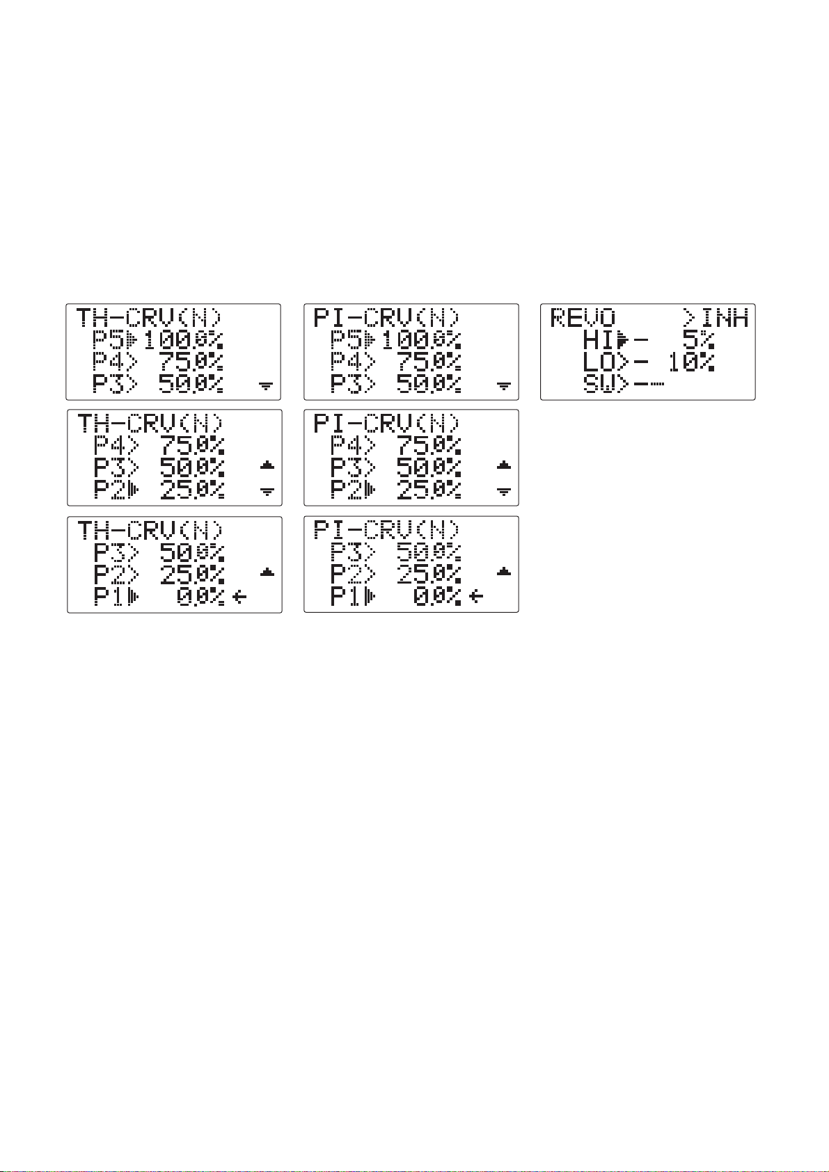
TH-CV/NOR: inputs the normal (NORM) throttle curve, which is usually not a linear response to T
HROTTLE STICK motion
Adjusting point 3 of the curve adjusts the engine's RPM at the THROTTLE STICK midpoint - the desired position for
hovering. The other 4 points are then adjusted to create the desired idle and maximum engine speed, and a smooth
transition in-between. For more on throttle curves, see p. 69.
PI-CV/NOR: inputs the normal (NORM) collective pitch curve, the collective pitch curve for flight near hover. The
normal collective pitch curve is adjusted to match the throttle curve, providing the best vertical performance at a
constant engine speed, with a starting curve of -4 base, +5 neutral, and +8 to +10 degrees of blade pitch maximum*.
You can program the response over a 5-point curve for the best collective pitch angle relative to THROTTLE STICK
movement. For more on collective pitch curves, see p. 69.
REVO.:mixes collective pitch commands to the rudder (a PITCH-RUDDER mix) to suppress the torque generated by
changes in the main rotor's collective pitch angle, keeping the model from yawing when throttle is applied. REVO.
is extremely helpful in "taming the tail" of models not using heading-hold/AVCS gyros. Never use revo. mixing
in conjunction with a heading-hold/AVCS gyro while in heading-hold/AVCS mode.
Revo. mixing is still used with these gyros while set to the normal mode. For details on revo, including default points
for clockwise and counterclockwise rotating rotors, see p. 69.
65
Page 66

HROTTLE
Note:Besure to add the step of setting a trigger point by cursoring to THR, then putting th
THROTTLE STICK in the desired position and pressing and holding the dial for one second
Notice that this function cannot be reversed to trigger only above the stick point.
66
Open the THR-CV/NOR function.
Adjust the first point. (Ex: 5%.)
Open the PIT-CV/NOR function.
Adjust the first point. (Ex: 8%.)
Open the REVO. function.
(Ex: High 5%, Low 10%.)
Adjust THR-CV/NOR.
Adjust PIT-CV/NOR.
Adjust THR-CV/NOR.
Adjust PIT-CV/NOR.
for 1 second.
(If ADVANCE, again.)
to THR-CV/NOR.
to 5%.
to PIT-CV/NOR.
to 8%.
to REVO.
to 5%.
Repeat above as needed.
Repeat above as needed.
Repeat above as needed.
Repeat above as needed.
GYRO function: see p. 72.
Adjust HOV-THR and HOV-PIT if needed: see p. 71.
Setting up Throttle Hold: see p. 67.
Setting up idle-ups 1 and 2: Throttle and collective pitch curves and revo.
mixing (TH-CURVE, PI-CURVE, REVO. MIX): see p. 69.
D/R,EXP: see p. 34.
to 10%.
Page 67

HROTTLE STICK when SWITCH
Prior to setting up THR-HOLD, hook up the throttle linkage so that the carburetor
opened fully at high throttle, then use the digital trim to adjust the engine id
position. To have THR- HOLD maintain idle, move the THROTTLE STICK to the id
position, then move the hold SWITCH on and off and keep changing the offset valu
until the servo does not move. To lower the engine idle speed, or if you want to sh
off, input a more negative number.
Adjustability:
Idling position: Range of -50% to +50%centered about the throttle idle position to get the desired engine RPM.
Rudder offset:Offsets the tail rotor pitch. Keeps the fuselage from rotating in throttle hold.
Switch assignment: Assigned to S
WITCH G (7CA) or E (7CH) down. Not adjustable.
Throttle curve: Since the throttle is moved to a single preset position, no curve is available for THR-HOLD.
Collective pitch curve: Independent curve, typically adjusted to create a blade pitch range of -4° to +10° to +12°,is
automatically activated with THR-HOLD.
Revo. mix:Since revo. mix adjusts for torque from the engine, no revo. mix is available for THR-HOLD.
Priority: The throttle hold function has priority over idle-up. Be sure that the throttle hold and idle-up S
WITCHES are in the
desired positions before trying to start the engine. (W e recommend starting your engine in throttle hold for safety reasons.)
Gyro: Gyro programming includes an option to have a separate gyro setting for each condition, including THR-HOLD.
This avoids the potential problem of the user being in the wrong gyro setting when going to THR-HOLD,resulting in a
improper rudder offset and the model pirouetting.
67
Open THR-HOLD function.
Activate the function.
Set desired engine position.
Optional: set up a rudder offset.
Close.
for 1 second.
(If basic, again.)
to THR-HOLD.
to OFF.
to desired percent.
to OFF.todesired offset.
PIT-CURVE for THR-HOLD:seep. 69.
GYRO setup: see p. 72.
Setting up the Idle-Ups: Throttle and Collective pitch Curves and Revo. Mixing
(TH-CURVE, PIT-CURVE, REVO. MIXING) for idle-ups: see p. 69.
D/R,EXP: see p. 34.
Page 68

Normal:Collective pitch curve thatresults in points 1, 3 and 5providing -4, +5, (+8to +10)* degreespitch. A throttle
curve setting of 0, 30, 50, 70, 100%.
Idle-up 1: Idle-ups 1 is typically the same except for the gyro settings, with heading-hold/AVCS mode.
The pitch curve will likely be similar to the normal curve above.
Idle-up 2: Collective pitch curve that results in points 1, 3 and 5 providing (-8 to -10), 0, (+8 to +10) degrees. A
throttle curve of 100, 75, 50, 75, 100 to provide full throttle for inverted maneuvers.
Throttle Hold pitch curve: Start with the normal pitch curve (for inverted autos, start from the idle-up 2 pitch curve), but
increase the last point approximately 1-2°,ifavailable, to ensure sufficient pitch at landing.
Normal condition curves are editable in the BASIC menu for convenience.
All curves may be adjusted in the ADVANCE menu.
Automatically selected with the proper condition.
The idle-up curves are adjusted by the modeler to maintain constant RPM even when the collective pitch is reduced
during flight (including inverted).
To change which condition's curve is being edited, simply press the MODE/PAGE BUTTON to scroll through the curves
available, or cursor up above point 1 and change the curve named.
For clarity, the name of the condition currently active (switched on in the radio) is shown in parentheses behind name
of condition whose curve is being edited.
Idle-ups and throttle hold pitch curves may be edited even before the conditions have been made active or while they
are active but not selected.
REVO.MIX: normal for hovering and idle-ups (1 and 2) combined.
REVO.MIX is editable in the BASIC and ADVANCE menu.
68
Page 69

Revo. mixing rates are linear curves. For a clockwise-turning rotor, the rudder is mixed in the clockwise direction
when collective pitch is increased; for counterclockwise-turning, the opposite. Change the operating direction setting
by changing the signs of the numbers in the curve from plus (+) to minus (-) and vice versa.
Revo. curves for idle-ups are often v-shaped to provide proper rudder input with negative pitch and increased throt
during inverted flight. (Rudder is needed to counter the reaction whenever there is increased torque. In inverted flight,
throttle stick below half has increased throttle and negative pitch, therefore increasing torque and rotating the
helicopter unless the revo. mix is also increasing appropriately.)
Adjustability:
S
WITCH G (7CA) or E (7CH) is programmed for normal (NORM), idle-up 1 (IDL1), and idle-up 2 (IDL2) curves. Thi
switch/position assignment is not adjustable.
Activated with the throttle curve for that condition in THR-CURVE.
Curves are adjusted to maintain constant RPM even when the collective pitch is negative (inverted).
Gyro settings may be set separately for each idle-up. (See p. 72.)
Activating OFFSET makes the T
RIM LEVERS adjust the trim separately in each of the idle-up conditions.
Dual rates may be set up to allow tri rates - a rate for each of the 3 primary controls in normal/idle up conditions.
For an example of throttle and pitch curves and revo, please see Normal Flight Condition Setup,p.65.
69
Page 70

Complete switch assignability, plus a CONDITION option that creates/switches between individual trims for each of th
idle-ups.
When OFFSET is active (its switch is on),moving the TRIM LEVERS adjusts the stored offset, not the trims in the normal
condition.
When OFFSET is inactive (its switch is off), the OFFSET and any trim adjustments to it have no effect (model obeys th
trim settings of the currently-active flight condition.)
Defaults to INH.
When OFFSET is inhibited, trim adjustments made in any flight condition affect all flight conditions.
70
Open the
Activate the function.
OFFSET function.
Change switch setting to E
Select IDL2.
Adjust trim settings as needed. (Ex:
rudder to +8%.)
Close menus and confirm difference in
trims between normal and idle-up 2.
for 1 second.
(If basic, again.)
to OFFSET.
to +8%.
E (7CH) or G (7CA) from
NORMALto IDL2. Check that rudder
trim changes.
THR-HOLD: see p. 67.
Setting up the Idle-Ups: Throttle and Collective pitch Curves and Revo. Mixing
(TH-CURVE, PIT-CURVE, REVO. MIXING for idle-ups: see p. 69.
to OFF.
to E.
to 2 (IDL2).
Page 71

Adjustability:
Rotor speed changes caused by temp., humidity
HOV-THR and HOV-PIT can assign the knob VR only to one of these functions at a time. Each time, assign the knob
,altitude or other changes in flying conditions are easily accommodated.
Both adjustments may be inhibited if not desired.
in these functions. Temporarily turning off the knob butmaintaining the last memorized setting.
Adjustments may be memorized and then the knobs returned to center point to use that amount of adjustment. Allows
easy use of the trimming knobs for multiple models. (Note that when memorization is repeated with the knob offset
from center, the trim value accumulates.)
Adjustments are quickly reset to the initial value by turning the dial until the trim reads 0%, memorizing, then
returning the knob to its center position.
Note that all functions, including these, assume the model hovers at half stick.
Available in normal condition only.
71
Open the HOV-THR function.
Assign the dial VR.
Store the current dial settings prior to
selecting another model.
Close.
Open the HOV-PIT function.
Store the current dial settings prior to
Change VR to OFF.
setting HOV-THR function.
Close.
for 1 second.
(If basic, again.)
to HOV-THR.
to ON.
for one second to store.
or VR to center.
to HOV-PIT.
for one second to store.
or VR to center.
THR-HOLD: see p. 67.
Setting up the Idle-Ups: Throttle and Collective pitch Curves and Revo. Mixing
(TH-CURVE, PIT-CURVE, REVO. MIXING for idle-ups: see p. 69.
D/R,EXP: see p. 34.
to OFF.
In flight, adjust throttle curve near hover point with the knob.
Page 72

• Normal: sense motion and dampen it (if the gyro rotates off course for 2 seconds, it corrects for 2 seconds).
• Heading-hold/AVCS: calculate the angle of rotation (by tracking the time/rate of change) and then provide correction
until the same rotation is achieved.
• Stick priority: a feature on most high-end gyros. The more input given on the channel the gyro controls, the less
sensitive the gain is automatically. This way,if you give a large input for a stallturn, for example, the gyro turns itself
off and does not fight the stall turn. As you ease off the rudder, the gain increases again, minimizing tail wag and
keeping the model straight. (If your gyro does not include stick priority, you can manually create it. Please see
www.futaba-rc.com\faq\faq-7c.html.)
• Mechanical: some are still available. They are very challenging to set up and not as reliable as piezo or SMM.
• Non-Heading-Hold Piezo: these are now inexpensive gyros that are reliable and easy to set up. Some have dual rates
and remote gain control to adjust sensitivity in flight. Lack heading-hold capabilities for precision flying.
• Heading-Hold Piezo: Until recently, the cream of the crop. Expensive, and more complex to set up. Adds GPS-like heading
recognition. Exhibits minor difficulties with temperature drift (position setting varying with unit's temperature).
• Heading-Hold SMM: 21st Century gyro technology. Computer chip technology. Expensive, easier set up, higher durability.
Significant decrease in temperature sensitivity. Many include frame rate settings to allow faster response when using
specialized digital servos. Examples:
• GY401: Simpler set up. Ideal for learning aerobatics through 3D.
• GY502: Better centering than 401 for more advanced aerobatics. Ideal through Class III competition.
• GY601: Exceptional center. Extremely fast response time. Requires specialized servo.
gain, the more correction the gyro provides and the "softer" or less responsive the helicopter feels.) This function
makes the best possible use of the inflight adjustable gain of most gyros..
• Plug the gyroís sensitivity adjustment to channel 5 of the receiver. (not assignable)
• STD and AVCS/Heading-hold (GY) setup types available to simplify adjustments for AVCS/Heading-hold gyros.
• Full switch assignability or may select Cond. option.
• Each gyro setting may be set from 0 to 100% gain.
• Dual mode gyros (heading-hold/AVCS and normal) are easily triggered to each mode by changing the gyro settingís
sign.
• Larger percentages indicate more gain, or gyro responsiveness.
• Tail wagging or shaking indicates excessive gain settings. Turn down gyro setting until wag stops.
72
Page 73

Gain Example for AVCS/Heading-hold Gyros (GY)
73
Set up a heading-hold/AVCS gyro with
heading-hold/AVCS setting in idle-up
1 and normal mode setting in
idle-up2 and normal.
Where next?
Open and activate the GYRO function.
Optional: change gyro type to
Heading-hold (GY).
Optional: change switch assignment.
Ex: select E.
Adjust gyro rates as needed. (Ex:
NORM to A80%, IDL1 to A70%, IDL2
to N70% as starting points.)
Close the function.
for 1 second.
(If basic, again.)
to GYRO.
to SW.
to E.
D/R,EXP: see p. 34.
to GY.
to A80%.
to A70%.
to N70%.
to ON
Page 74

74
T
HROTTLE STICK POSITION............................................................52
TL:Adjustable Travel Limited. Standard type of trim used for throttle, where the trim is effective only in the idle portion of the
HROTTLE STICK POSITION.Normal trims affect the entire travel of the servo (ex: elevator trims), but ATL trims only the low end
f the throttle movement, allowing throttle idle adjustments that don't over-drive the servo at full throttle. . . . . . . . . . . . . . . .31
TV: Older, less clear terminology for end point adjustment. See END POINT.
utorotation: The ability of a helicopter to land safely without engine power, using the stored energy in the blade's
otation to produce lift for flaring.
Page 75

HELI 58
HELI 58
HROTTLE STICK POSITION in F/S. . . . .........41
75
Copy model: see MODEL COPY.
Crow: see AIRBRAKE(ACRO).
Cursor: See SELECT BUTTONS.
Cyclic: horizontal controls on a helicopter. Cyclic pitch is typically called elevator. Cyclic roll is typically called aileron.
Page 76

76
levator-to-pitch mix: (HELI) used to adjust pitch to counter the loss of angle of attack when elevator input is given. Not
preprogrammed mix. See Programmable mix. .
LEVON: flying wing configuration with 2 servos working together to create both aileron and elevator action.
......45
levons: two surfaces, one on each wing, which work as both ailerons and elevators. See ELEVON.
ND BUTTON:control button used during programming to return to previous menu or close menu altogether.
ND POINT:often abbreviated EPA. Adjusts the total travel in each direction of proportional servos regardless of their control
ssignment. Ex: adjustment to AIL channel will adjust only the servo plugged into channel 1 even if being used as one of two
laperons or elevons. Note: End point is not an absolute; mixing can still drive the servo farther than this setting. . . . . . . . . . .32
ngine cut: see THR-CUT.
PA: see END POINT.
rror messages: warnings/cautions provided by the radio when potential problems may exist. . . . . . . . . . . . . . . . . . .19
xponential (D/R,EXP): adjustment to the relationship of STICK MOVEMENT to servo movement, typically used to soften
verly sensitive models around center. ............................................................34
Page 77

. .43
HANNEL 6KNOB.Mayalso be used as
...........................17
Function (F) mode of TRAINER,allows student radio to use the computer programming for that channel in the master radio.
77
yro, gyroscope: equipment that senses change in direction and provides input to compensate for that change. For
escription of aircraft use, see p. 56. For description of types, and helicopter use, see GYRO.
YR O (HELI ): gyro sensitivity programming designed to ease the setup and use of gyroscopes on model helicopters.
anual pages include extensive descriptions of gyro types. . . . . . . . . . . . . . . . . . . . . . . . . . . . . . . . . . . . . . . . . . . . .72
yros .........................................................................72
Page 78

HROTTLE STICK position (the ideal
78
Page 79

TICK movements. All 7C radios shipped in the US are Mode
TICK.Tochange mode, please visit www.futaba-rc.com.
ODE/PAGE BUTTON: control button on radio's face used in various parts of programming. . . . . . . . . . . . . . . . . . . . . .11
79
r
e
i-Cd: Nickel Cadmium rechargeable battery. Typically used to power transmitter and receiver. See Battery care
nd charging.
iMH: Nickel Metal Hydride rechargeable battery . Newer battery technology than Ni-Cd. Longer run times but more specific
eak charging requirements. [Require a (zero) delta peak charger labeled specifically for use with NiMH batteries.]
ORMAL(N): trainer mode that does not give student radio the computer programming features of the master radio. See Traine
T8S: standard transmitter battery pack. See Accessories.
ULL(--): not assigned or never changed. Ex: a mix which has a null switch assignment is always active, and can never b
hanged in flight (turned off) no matter which switch is moved.
Page 80

switch. When offset is ON, movement of the trim levers adjusts the OFFSET, not the normal condition's trims
......70
TICK. Independently adjustable in the normal flight mode, one for each of the 2 idle-ups, and one for throttle hold.
80
udder-to-throttle mix: (HELI) adds throttle to counter the added load from increasing pitch of the tail blades,
aintaining a constant head-speed with rudder. (This is a minor effect and is not critical in most helicopters.) Not a
reprogrammed mix. See Programmable mix.
x: receiver.
Page 81

...................................................................10
81
Page 82

HROTTLESTICK...............................31
HROTTLE STICK position along a 5 point curve. Separate
HROTTLE STICK position, and moves the throttle to idle.
and elevon. . . . .....................................................................43
V-tail. .............................................................................45
82
-tail model Mix: (ACRO ) programming used to control a V-tail modelís tail surfaces, with 2 servos operating 2 control
urfaces as both rudder and elevator.
arning messages: cautions provided by the radio when certain potential problems exist. See Error messages.
arranty information. . . . .......................................................................3
ebsite: www.futaba-rc.com. Internet location of extensive technical information Futaba products. . . . . . . . . . . . . . . .3
hip antenna: aftermarket, shortened antenna. Not approved by Futaba.
 Loading...