

Page 1
Model Selsct "MDL SELE"
Forty model data (data for 40 R/C cars) can be saved in the T4PM transmitter. This
menu selects the model and copies data between models.
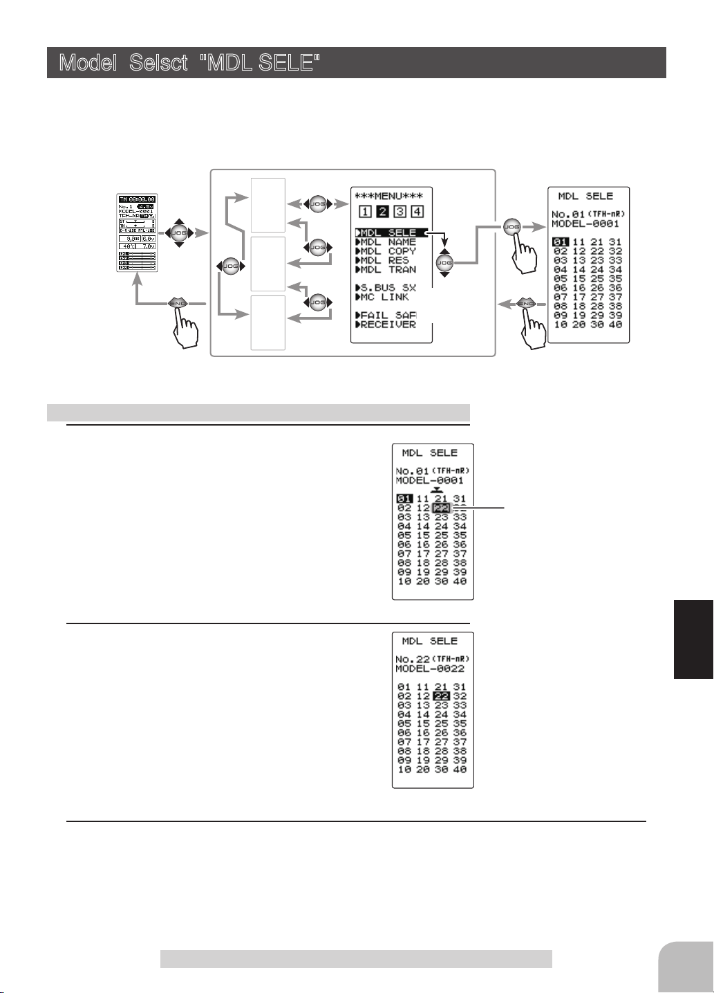
Display "MDL SELE" screen using the following method:
(HOME screen)
Using the model select function
1
(Model #. selection)
Select the model number by moving the (JOG)
button up/down or left/right. "01" ~ "40" are displayed.
MENU-1
MENU-3
MENU-4
(MENU 2 )
(MDL SELE screen)
Select
"MDL SELE"
Model #.
01~40
Move the cursor to select model
# with the (JOG) button.
2
(Model select execution)
Press the (JOG) button for approximately 1 second. A beeping sound is generated and the model is selected.
- Model change is complete when the model number and model
name on the screen change.
3
When finished with setting, return to the MENU screen by pressing the (END) button.
Model Selsct "MODEL SELECT"
Function
59
Page 2

Model Name "MDL NAME"
This function allows you to assign a ten character name to each model memory and us-
er name.
Display "MDL NAME" screen using the following method:
(HOME screen)
(MENU 2 )
MENU-1
(MDL NAME screen)
Model name
MENU-3
Select
MENU-4
"MDL NAME"
Setting the model name and user name
1
(Move the cursor to the character you want to change.)
Select the model name or user name character you want to set
or change by moving the cursor by the (+) or (-) button. The selected character blinks.
When (JOG) button left or right operation is performed from both the left
and right ends of the character list, the page (all 3 pages) is changed
and the character set is selected.
(KATAKANA of the 3rd page is displayed when "KANA" is set by the
"SYSTEM" function "MENU".)
User name
Move the cursor to the char-
acter you want to change by
(+) or (-) button.
60
2
(Selecting the character to be used)
Function
Move the (JOG) button up, down, left or right to select the
character you want to use from the list at the bottom of the
Select the character by
(JOG) button.
screen. The selected character blinks. Now, press the (JOG)
button. The character is entered and the model name or user
name character. The cursor will automatically move to the right
for the next characters.
Use the (JOG) button also to move the cursor to "RESET".
Press the button approximately 1 second. You'll hear a beeping sound, which indicates that the model name has been initialized into the factory settings. A beeping sound is generated
and the model name is initialized to the factory setting.
3
When finished with setting, return to the MODEL screen by
Move the cursor to "RE-
SET" by the (JOG) button
up or down operation.
pressing the (END) button.
Model Name "MDL NAME"
Page 3

Model Copy "MDL COPY"
The contents of the currently selected model data can be copied to another model.
Display "MDL COPY" screen using the following method:
(HOME screen)
Using the model copy function
1
(Model #. selection)
Select the copy destination model number with
the (+) or (-) button. "01" ~ "40" are displayed.
MENU-1
MENU-3
MENU-4
(MENU 2 )
(MDL COPY screen)
Select
"MDL COPY"
Model #.
01~40
The copy destination model #
with the (+) or (-) button.
2
(Model copy execution)
Press the (JOG) button for approximately 1
second. A beeping sound is generated and the
model is selected.
Model name is also copied.
"COMPLETE!" is displayed.
-Copying is complete when "COMPLETE!" is displayed on the screen.
3
When finished with setting, return to the MENU screen by pressing the (END) button.
Model Copy "MDL COPY"
Function
61
Page 4
Model Reset "RES"
This function resets and initializes the contents of the currently selected model data.
However, the adjuster function (ADJUSTER), system setting (SYSTEM), and type of
receiver system (RECEIVER) are not initialized.
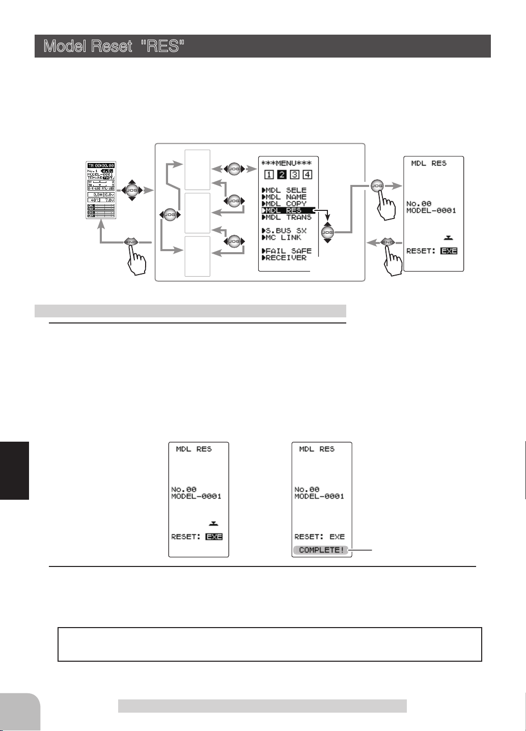
Display "MDL RES" screen using the following method:
(HOME screen)
Using the model reset function
1
(Model reset execution)
Press the (JOG) button for approximately 1
second. A beeping sound is generated and the
model is selected.
-Resetting is complete when "COMPLETE!" is displayed on
the screen.
MENU-1
MENU-3
MENU-4
(MENU 2 )
(MDL RES screen)
Select
"MDL RES"
62
Function
"COMPLETE!" is displayed.
2
When finished with setting, return to the MENU screen by pressing the (END) button.
The set receiver system and T-FHSS receiver ID remain even if the model is reset.
The same receiver can be used as is without re-linking.
Model Reset "RES"
Page 5
Data Transfer "MDL TRANS"
This function copies the model memory data of one T4PM to another T4PM. Connect
the communication port of both T4PMs with the optional DSC cable (For updating
transmitter with CIU-3).
Note: If the T4PM battery voltage drops, the display switches to low battery display.
Therefore, use this function when there is ample battery capacity remaining.
Note: Since the receiving side writes the new contents of the currently selected model
memory, always check the model number before executing this function.
Data is not interchangeable with another type of transmitter.
Communication port
Connect the communication port of both
T4PM with the optional DSC cord.
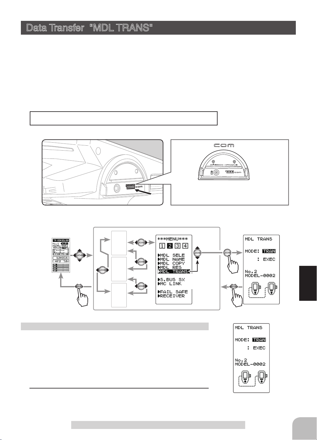
Display to "MDL TRANS" screen using the following method:
(HOME screen)
Using the Data Transfer function
(Preparation)
- Connect the communication port of both transmitters with the
optional DSC cord.
- Turn on the power of both T4PMs. Select the model number of
the transfer side and the receiving side with the model select
function (page 59).
1
Display the data transfer function screen in the above manner.
MENU-1
MENU-3
MENU-4
(MENU 2 )
Select
"MDL TRANS"
(MDL TRANS screen)
Function
Data Transfer "MDL TRANS"
63
Page 6
2
(Select the setting item )
Select "MODE" by moving the (JOG) button up
or down, and select the transfer side and receiving side using the (+) or (-) button.
TRAN": Data transfer side.
"
RECV": Data receiving side.
"
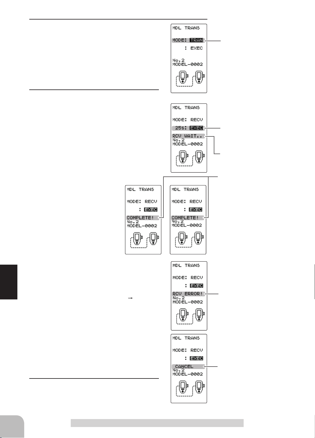
3
(Data transfer execution)
Select the setting item "EXEC" by moving the
(JOG) button up or down on both transmitters.
First, press the receiving side "RECV" transmitter (JOG) button. The message "RCV WAIT.."
appears and countdown begins.
Within 30 seconds, press the transfer side
"
TRANS" transmitter (JOG) button. (If data
transfer is not executed within
30 seconds, an error will be
displayed at the receiving side
"
RECV" transmitter.)
Mode selection
"TRANSFER" "RECEIVE"
Setup item selection
- Select by (JOG) button up or
down operation.
Mode change button
- Use the (+) and (-) buttons to
make adjustments.
Transfer execution button
- (JOG) button pressed.
*30 seconds wait is displayed
on the receive side screen.
"COMPLELE!" is displayed.
-"COMPLETE!" is displayed
on the screen of the receiving
side "RECV" transmitter and
data transfer is ends.
-If "RCV ERROR!" is displayed on the screen of
the receiving side "RECEIVE" transmitter, data
transfer was not performed normally. Check the
Function
connection and repeat steps 1
3. Since the
"RCV ERROR!" is displayed.
transfer side "TRANS" transmitter only sends,
"COMPLETE!" is displayed even when data
transfer was not performed normally.
Data transfer can also be canceled before the
end of transfer by operating the (JOG) button at
a T4PM that is waiting to receive data.
"CANCEL" is displayed.
4
When finished with setting, return to the MENU
screen by pressing the (END) button.
64
Data Transfer "MDL TRANS"
Page 7
Fail-safe Function "FAIL SAFE"
Fail-safe Mode (F/S)
(All channel)
This function moves each servo to a preset position when the receiver cannot receive
the signals from the transmitter for some reason.
-The fail-safe data is transferred from the transmitter to the receiver 10 seconds after
the transmitter power was turned on. The data is transferred every 5 seconds after that.
Be careful because normally the transmitter power is turned on rst and the receiver
power is turned on next and the data is transferred for approximately 10 seconds after
the receiver power is turned on.
-For gas power cars, for safety we recommend that this fail-safe function be used to set
the throttle channel in the direction in which the brakes are applied.
Hold mode (HOLD)
This function holds the receiver in its position immediately before reception was lost.
Off mode (OFF)
This function stops output of signals to the servos and places the servos into the free
state when the receiver cannot receive.
*The F/S, HOLD, and OFF modes are automatically reset when signals from the trans-
mitter can be received again.
Battery fail-safe function (B-FS)
If the receiver battery voltage drops below a certain value when this function is enabled, the throttle servo moves to the position set by fail-safe function. When the battery voltage recovers, the battery fail-safe function is automatically reset.
-This function cannot be used when the throttle (TH) is not set to fail-safe (F/S).
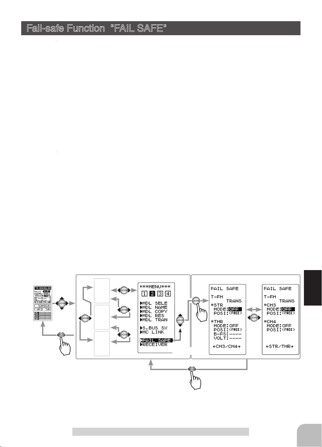
Display to "FAIL SAFE" screen using the following method:
(HOME screen)
(MENU 2 )
MENU-1
MENU-3
MENU-4
Setting item
MODE: F/S mode selection
POSI: F/S positon set
B-FS: B-FS set (throttle only)
VOLT: B-FS voltage set (throttle only)
Select
"FAIL SAFE"
(FAIL SAFE screen)
Function
Fail-safe Function "FAIL SAFE"
65
Page 8

Fail-safe mode selection
(Preparation)
- Select the channels "MODE" to be set by moving the
(JOG) button up, down, left or right.
1
(Mode selection)
Select the mode by (+) or (-) button.
(Each channel can be individually set.)
2
When finished with setting, return to the MENU
screen by pressing the (END) button.
When setting fail-safe, set the servo position by the following
method.
Fail-safe function setup
1
(Servo position setup)
When the fail-safe function operates, select the setting item
"POSI" by moving the (JOG) button up or down. The steering wheel, the throttle trigger or 3rd, 4th channel dial remains
in the desired operation position. When the (JOG) button is
pressed for approximately 1 second, the servo position is displayed and you can confi rm that the function was set.
(Each channel can be set similar.)
FAIL SAFE screen
F/S mode
OFF, HOLD, F/S
F/S mode selection
- Select with the (+) or (-) buttons.
F/S position setup button
- The (JOG) button is pressed
for approximately 1 second.
2
When finished with setting, return to the MENU screen by
pressing the (END) button.
Battery fail-safe function ON/OFF
(Preparation)
- Select the setting item by moving the (JOG) button up or down.
For Battery F/S function select "OFF" or "ACT" of "B-FS".
Function
system only. )
The S-FHSS system is fi xed at 3.8v.
For voltage setting, select VOLT. (This applies to the T-FHSS
1
(Battery fail-safe function ACT/OFF)
The battery fail-safe function ACT/OFF and voltage setting which activates the B-FS function
can be switched by (+) or (-) button.
2
When finished with setting, return to the MENU screen by
pressing the (END) button.
Battery fail-safe function
OFF, ACT
Initial value: OFF
Select button
- Select with the (+) or (-) buttons.
B-F/S Voltage
3.8, 4.0, 4.2, 4.4, 4.6, 4.8,
5.0, 5.3, 5.6, 5.9, 6.2, 6.5,
6.8, 7.1, 7.4(V)
Initial value 3.8v
Select button
- Select with the (+) or (-) buttons.
Example:
Ni-MH /Ni-Cd 4cell---3.8V
Ni-MH /Ni-Cd 6cell---4.4V
LiFe 2cell---4.8V
Li-Po 2cell---5.6V
66
Fail-safe Function "FAIL SAFE"
Page 9

Select TRIM Dial Function "TRIM DIAL"
Selection of the function to be performed by trims and dial (DT1, DT2, DT3, DT4,
DT5, DL1).
-
The functions that can be assigned to dial and digital trim are listed on the next page.
- The
dial and digital trim
step amount is shown in the table on the next page.).
- The operation direction can be reversed (NOR/REV).
Display "TRIM DIAL" screen using the following method:
step amount can be adjusted (The relationship between set value and
(HOME screen)
MENU-1
MENU-2
MENU-4
(MENU 3)
Function select trim/dial setting
1
(Setting trim/dial selection)
Select the trim or dial you want to set by moving the (JOG)
button up or down.
2
(Function setting)
Select the function with the (+) or (-) button.
- Refer to the list on the next page for the abbreviations of the functions.
(Step amount setting)
Select the step amount you want to set by moving the (JOG)
button up or down. Use the (+) or (-) button to set the step
amount.
- Refer to the next page for the relationship between set value and step amount.
(Changing the direction of operation)
Select the direction of operation you want to set by moving the (JOG) button up or down. Use the (+) or (-) button to
trim/dial the direction.
Select
"
T R I M D IA L"
(TRIM DIAL screen)
Adjustment buttons
- Use the (+) and (-) buttons to
make adjustments.
- Return to the initial value by
pressing the (+) and (-) buttons
simultaneously (approx. 1 sec).
*Function selection
Function
*Step amount set-
ting
*Direction of oper-
ation setting
3
When finished with setting, return to the MENU screen by
pressing the (END) button.
Function Select Trim Dial "TRIM DIAL"
67
Page 10

DT1
DT4
DL1
DT3DT2
DT5
Set table functions (DL1, DT1/DT2/DT3/DT4/DT5)
Abbreviation
used on setup
screen
D/R Dual rate function
AT L ATL function
EXP-ST Steering EXP
EXP-FW Throttle EXP (Forward side)
EXP-BK Throttle EXP (Brake side)
SPD-TN Steering speed (Turn side)
SPD-RN Steering speed (Return side)
ABS.PS A.B.S. function (Return amount)
ABS.DL A.B.S. function (Delay)
CYCLE A.B.S. function (cycle speed)
ACC-FW Throttle acceleration (Forward side)
ACC-BK Throttle acceleration (Brake side)
TH-SPD Throttle speed
ST-TRM Steering trim
TH-TRM Throttle trim
CH3 Channel 3
CH4 Channel 4
Function
SUBTR1 Sub trim (CH1)
SUBTR2 Sub trim (CH2)
SUBTR3 Sub trim (CH3)
SUBTR4 Sub trim (CH4)
IDLE Idle up function
ESC-RT Dual ESC mixing (4ch ESC rate)
TH-OFF
PMX-A Program mixing (RGHT/BRAK/DOWN sides)
PMX-B Program mixing (LEFT/FWRD/UP sides)
BK3-RT Brake mixing (3ch brake rate)
BK4-RT Brake mixing (4th brake rate)
4WS-RT
ESC-MD Dual ESC mixing (Drive mode select)
GYRO Gyro mixing (Gain rate)
ACKMAN Ackermann mixing (ackermann rate)
OFF
Throttle off (engine cut)
4WS mixing (3ch steering rate)
Not used
Function name, etc
Relationship between set value
and step amount
(Setting range: 1~10, 20, 30, 40, 50, 100, 2P)
-Steering trim/throttle trim
When set to the minimum "1", the total trim
operating width is 200 clicks. For "100", the
total operating width is 2 clicks and for 2P, the
total operating width is 1 click.
-Rate, etc. setting
This is the % value which is operated by 1
click relative to the set value of each rate.
Since the total operating width of functions
having a rate of -100~0~+100 is 200%, when
set to "100", the total operating width is 2
clicks. Since the total operating width of functions with a 0~100 rate is 100%, "100" and 2P
are operated by 1 click.
-Channel 3/4
When set to the minimum "1", the total op-
erating width of channel 3 is 200 clicks. For
"100", the total operating with is 2 clicks and
2P is operated by 1 click.
68
Function Select Trim Dial "TRIM DIAL"
Page 11

Select Switch Function "SWITCH"
Selection of the function to be performed by the switches (SW1, SW2).
- SW2 alternate operation (operation which switches between ON and OFF each time the switch
is pressed) is possible.
NOR (Normal) -ON only while pressed, OFF when released.
ALT (Alternate) -Switched between ON and OFF each time pressed.
- SW1 ON/OFF direction can be reversed (NOR/REV).
Display "SWITCH" screen using the following method:
(HOME screen)
MENU-1
MENU-2
MENU-4
(MENU 3 )
Function select switch setting
1
(Setting switch selection)
Select the switch you want to set by moving the (JOG) button
up or down.
2
(Function setting)
Select the function with the (+) or (-) button.
- Refer to the list on the next page for the abbreviations of the
functions.
(Changing the SW1 operation direction)
Select "DIRECTION" of "SW1" by moving the
(JOG) button up or down. Select REV or NOR
with the (+) or (-) button.
(Changing the SW2 operation system)
Select "DIRECTION" of "SW2" by moving the
(JOG) button up or down. Select ALT or NOR
with the (+) or (-) button.
Select
"
SWITCH"
(SWITCH screen)
*Function selection
Select button
- Select with the (+) or (-) buttons.
Adjustment buttons
- Use the (+) and (-) buttons to
make adjustments.
- Return to the initial value by
pressing the (+) and (-) buttons
simultaneously (approx. 1 sec).
SW1 ON/OFF direction
SW2 alternate operation
Function
3
When finished with setting, return to the MENU screen by pressing the (END) button.
Function Select Switch "SWITCH"
69
Page 12

SW1
SW2
Set table functions (SW1)
Abbreviation used on setup screen
NT-BRK Neutral brake function ON/OFF
ABS A.B.S function ON/OFF
IDLE Idle up function ON/OFF
PRGMIX Program mixing function ON/OFF
TH-OFF
CH3 Channel 3
CH4 Channel 4
GYRO Switching GYRO mode
OFF Not used
Throttle off (engine cut)
Function name, etc
function ON/OFF
70
Set table functions (SW2)
Abbreviation used on setup screen
Function
NT-BRK Neutral brake function ON/OFF
ABS A.B.S function ON/OFF
IDLE Idle up function ON/OFF
PRGMIX Program mixing function ON/OFF
TH-OFF
CH3 Channel 3
CH4 Channel 4
GYRO Switching GYRO mode
4WS 4WS mixing type select
TIMER Timer function start/stop
LOGGER Telemetry log start/stop
OFF Not used
Function Select Switch "SWITCH"
Throttle off (engine cut)
Function name, etc
function ON/OFF
Page 13

Adjuster "ADJUSTER"
Steering wheel and throttle trigger neutral position and servo operating angle correction can be applied. This is used when a mechanical offset has occurred for some rea-
son.
*However, when correction is made, the set value of all the setting functions must be
rechecked.
Display the "ADJUSTER" screen using the following method:.
(HOME screen)
Steering adjustment
(Preparation)
On the ADJUSTER screen, select the setting item "WHEEL"
by moving the (JOG) button up or down, and press the (JOG)
button.
1
(Steering neutral adjustment)
In the neutral setup screen (fi g-1) state, lightly pull the steering
wheel and then press the (JOG) button without touching the
wheel.
MENU-1
MENU-2
MENU-3
(MENU 4)
Select
"
ADJUSTER"
(ADJUSTER screen)
fi g-1
2
(Steering throw adjustment)
In the throw setup screen state (fi g-2), lightly turn the wheel
fully to the left or right and when button mark (fig-3) is displayed, press the (JOG) button.
Internal check is performed automatically. When each adjustment point is within a fi xed range, correction is performed and
"COMPLETE" (fi g-4) is displayed.
If an adjustment point is not within a fi xed range, correction is
not performed and the correction data is not updated.
When button mark is not displayed even though correction was
performed again, please contact a Futaba Radio Control Customer Center.
3
When finished with setting, return to the ADJUSTER screen by
pressing the (END) button.
Adjuster "ADJUSTER"
fi g-2 fi g-3
Function
fi g-4
71
Page 14

Throttle adjustment
(Preparation)
On the ADJUSTER screen, select the setting item "THROTTLE" by moving the (JOG) button up or down, and press the
(JOG) button.
1
(Throttle neutral adjustment)
In the neutral setup screen (fig-1) state, lightly pull the throttle
trigger and then press the (JOG) button in without touching the
trigger.
2
(Throttle throw adjustment)
In the throw setup screen state (fig-2), lightly operate the trigger fully to the brake side and the forward side and when button mark (fig-3) is displayed, press the (JOG) button.
Internal check is performed automatically. When each adjustment point is within a fixed range, correction is performed and
"COMPLETE!" (fig-4) is displayed.
If an adjustment point is not within a fixed range, correction is
not performed and the correction data is not updated.
When button mark is not displayed even though correction was
performed again, please contact a Futaba Radio Control Customer Center.
fig-1
fig-2 fig-3
fig-4
72
3
When finished with setting, return to the ADJUSTER screen by
pressing the (END) button.
Function
Adjuster "ADJUSTER"
Page 15

Infomation "INFO"
Display version of T4PM program, ID information.
Display the "INFO" screen using the following method:.
(HOME screen)
MENU-1
MENU-2
MENU-3
(MENU 4)
Select
"
INFO"
(INFO screen)
Function
Infomation "INFO"
73
Page 16

Software Update
Whenever improvements and new functions are available, the software of your T4PM
radio transmitter can be updated easily online free of charge. The zip le of the update
data will be shown on our website. You can download it and make a copy on your mi-
croSD card.
Below is the procedure for the software update.
Caution:
should be fully charged.
Update method
1
Extract the zip file on your computer. The "FUTABA" folder will be created on your computer
and copy the "FUTABA" folder onto your microSD card.
Note: If the microSD card has already had "another FUTABA" folder before you make a copy, the "FUTABA" folder is
OVERWRITTEN.
2
Insert the microSD card with "FUTABA" folder that contained the update software into the
SD card slot on your the T4PM.
3
Turn on the T4PM power while pressing
down the "END" button. The software update
is started.
Before you update the software, the battery that is connected to the T4PM
*Insert the card with the metal terminals side at the bottom.
*Remove the card by pushing it in and then pulling it out.
*Install and remove the card by pushing it in until you hear
a click.
Cover
4
When the software update is completed,
"SUCCESS" message is shown on the LCD
display of your T4PM.
Function
5
Turn off the power switch of your T4PM and
remove the microSD card from the card slot.
(Commercial product)
SD standard and SDHC standard microSD cards
SD/SDHC format. Maximum size 32GB.
(Some models may not be operated by card.)
SDXC format is not supported.
*The data in the memory card cannot
be guaranteed regardless of the con
tents and cause of trouble or damage. Always back-up the valuable
data in the memory card.
-
Caution
Always insert and remove the microSD card in the state in which the transmitter power is off.
If the microSD card is removed while being accessed (read or write), the card itself and the data may be destroyed.
Do not install and remove the microSD card with the microSD card slot facing your face.
If you remove your fingers quickly, the microSD card may fly out and strike your face and is dangerous.
Since the microSD card is a precision device, do not subject it to unreasonable force or shock.
74
Software Update
Page 17

Other Functions
Refer to country distributor WEB for detailed the following function explanation.
Function List
Function Abbreviation Description Of Function
TH A.B.S
TH MODE
S.BUS SX
MC LINK
STR MIX
BRAKE MIX
GYRO MIX
4WS
DUAL ESC
CPS MIX
PROG MIX
TIMER
LAP LIST
Pumping brake
Throttle servo neutral position/ Idle-Up/ Neutral brake/ Engine cut
Futaba S.BUS/S.BUS2 servo parameter setup.
MC851C, 602C, 402CR, 950CR, 940CR, 960CR, 970CR parameters setting function.
Uses 2 servos to individually control the left and right steering.
Front and rear independent brake control for 1/5 gas power car, etc.
The sensitivity of Futaba car rate gyros can be adjusted.
4WS mixing
Front and rear ESCs mixing
The CPS-1 of Futaba LED controller can be adjusted.
Programmable mixing between arbitrary channels.
Up, down, or lap timer
Lap timer data (lap time, total time) check.
TELEMETRY
LOG
INFO
Displays the status during operation of each sensor unit and records the status in a data log.
Log Setting, Start/ Stop
Display the transmitter program number and ID number.
Other Functions
Function
75
Page 18

Reference
Ratings
*Specications and ratings are subject to change without prior notice.
Communication method: One-way operation system
Maximum operating range: 100m (Except the MINIT system) (Optimum condition)
For safety: F/S, B-F/S, ID
Transmitter T4PM-2.4G
(T-FHSS SR / T-FHSS/S-FHSS system, wheel type, 4 channels)
Transmitting frequency band:
2.4GHz band
RF power output:
100mw EIRP
Power requirement:
(Dry cell battery) Penlight x 3 (4.5V)
Current drain:
150mA or less
Transmission antenna:
1/2λ di-pole
Receiver R304SB / R304SB-E / R314SB / R314SB-E:
Receiver R334SBS / R334SBS-E:
(T-FHSS/T-FHSS SR system, 4 channels)
(T-FHSS system, 4 channels)
Power requirement:
4.8V~7.4V battery / 3.5 ~ 8.4V useable (Dry cell battery cannot be used.)
Receiving frequency band:
2.4GHz band
RF power output:
10mw EIRP
System:
T-FHSS system (auto detection)
(excluding a projection part)
Size:
R304SB / R304SB-E: 1.38x0.91x0.33" (35.1x23.2x8.5mm)
R314SB: 1.38x0.91x0.33" (35.1x23.2x8.5mm) / R314SB-E: 1.38x0.91x0.49" (35.1x23.2x12.5mm)
R334SBS / R334SBS-E: 1.33x0.88x0.44" (33.9x22.3x11.3mm)
Weight:
R304SB/R304SB-E: 0.23oz. (6.6g) / R314SB: 0.23oz. (6.6g) / R314SB-E: 0.25oz. (7.0g)
R334SBS: 0.26oz. (7.5g)/ R334SBS-E: 0.25oz. (7.2g)
System Compatibility
The T4PM is a 2.4GHz T-FHSS SR / T-FHSS surface system. The transmitter can also be switched to S-FHSS. The usable receivers are
shown below. (However, the telemetry system cannot be used with T-FHSS SR and S-FHSS.)
Communications System Usable Receivers
Reference
T-FHSS (Default)
T-FHSS SR (Change is possible)
R304SB / R304SB-E
R314SB / R314SB-E / R324SBS
R334SBS / R334SBS-E
*R3008SB, T-FHSS Air system receivers do not operate.
R334SBS / R334SBS-E
76
S-FHSS (Change is possible)
NOTE:
The T-FHSS surface system and T-FHSS Air system are different. The T4PM cannot be used with the R3008SB or TFHSS Air system receivers.
R203GF / R2104GF / R204GF-E
Page 19

Warning Displays
Low Battery Alarm
When the battery voltage of the transmitter falls below the usable range, an audible
alarm will sound and
LCD screen:
(HOME screen) (MENU 1, 2, 3) (Function screen)
"
will be displayed on the LCD screen.
"
Audible alarm:
Continuous tone.
Warning
When a low battery alarm is generated, cease operation immediately and retrieve the model.
If the battery goes dead while in operation, you will lose control.
Power supply and low battery alarm
The T4PM can use an optional rechargeable battery. However, the battery alarm setting
is different from that of the dry cell battery (alkaline battery recommended). Therefore,
always set the battery type to match the power source used. Always set the battery type
to "LiFe2" especially when using a Futaba rechargeable type battery. If the set is used
at "DRY3" setting, the time from low battery alarm to system stopping will become ex-
tremely short. (See page 41, for a detailed description of the battery types.)
Memory Error
LCD screen:
If the data in the transmitter is not transferred normally
when the power is turned on, an audible alarm will sound
and "MAIN MEMORY BACKUP ERROR" will be dis-
played on the LCD.
- To stop the alarm, turn off the power.
- Turn the power back on. If the alarm is not generated again, there is no
problem.
Audible alarm:
Tone sounds (7 times) and stops (repeated)
Reference
77
Page 20

MIX Warning
LCD screen:
Power off forgotten warning
LCD screen:
When the power switch is turned on while the idle-up, preset
(engine cut) or neutral brake function switch is on, an audible
alarm will sound and "MIX WARN" will be displayed on the
LCD. When that function switch is turned off, the alarm will
stop.
Audible alarm:
Tone sounds (7 times) and stops (repeated)
If the T4PM is not operated for 10 minutes, an audible
alarm is sounded and "OPE WA R N" is displayed on the
screen. The audible alarm stops when the steering wheel,
throttle trigger, and any dial, switch, or edit button is operated. If you are not going to use the transmitter, turn
the power off. (Setting can be reset at the system menu on
page 42.)
Audible alarm:
Tone sounds (7 times) and stops (repeated)
The following parts are available as 4PM options. Purchase them to match your application. For other optional parts, refer to our catalog.
Transmitter Battery
When purchasing a transmitter battery use the following:
FT2F1100 (6.6V/1100mAh) / FT2F1700V2 (6.6V/1700mAh) / 2100BV2 (6.6V/2100mAh)
LiFe battery
Please do not use the transmitter batteries ( FT2F1100B /
ceiver's battery.
Since the transmitter's battery has an overload protection circuit, the output power will be shut
down when the high current load is applied. This may result in runaway or fatal crash.
Reference
Telemetry Sensor
Usable sensor options (As of December 2018)
Voltage Sensor (SBS-01V) / Temperature sensor (SBS-01T) / Temperature sensor (SBS01TE) / RPM Sensor (SBS-01RM) / RPM Sensor (SBS-01RB) (Brushless type) /
Current sensor (SBS-01C) / GPS sensor (SBS-01G)
Optional Parts
FT2F1700V2 / 2100BV2)
as the re-
78
Page 21

T7PX/T4PM Handle
This handle is option part for carrying T4PM. Please read the installation instructions
of the handle carefully for mounting method and precautions.
Using the screw
(3.0x12mm cap screw)
Other
-DSC cable for data transfer (For updating transmitter with CIU-3)
-Inductive Charging System ICS LF-01
(Li-FePO4 battery inductive charger for T7PX / T4PV / T4PM)
-Dry Battery Box for Transmitter 3P-SQ
(It is a standard item attached to T4PM.)
Reference
79
Page 22

When Using Four Dry Batteries
When ribs in the battery case are cut by the following method.
Cut rib
Cut out the six ribs inside the battery case referring to the figure.
-
- Insert the dry battery box 4P-SQ
from the wiring side as shown
above.
Coution
When putting the dry battery box in the transmitter, please put it in the case from the side with wiring. Also,
when removing, please remove from wiring side.
When installing and removing from the side opposite to the instruction, there is a possibility that the wiring is caught in the case and it
is disconnected or short-circuited.
Warning
Reference
Be alert when using a cutter knaife or nipper.
Failure to use it or neglect attention may cause injury and is extremely dangerous.
Low battery alarm
When changing to four the AA size dry batteries, be sure to change the battery type to
CSTM" and set the low battery alarm voltage to 4.1 V with the BATT setting (see page
"
41) of the system menu.
80
Page 23

Warranty & Repair Service (In U.S.A)
(Warranty)
Read the Warranty card.
- When requesting warranty service, send the card or some type of dated proof pur-
chase.
Technical updates and additional programming examples can be found at: www.futabausa.com
(Information needed for repair)
If any difculties are encountered while setting up or operating your T4PM, please consult the instruction manual rst. For further assistance you may also refer to your hobby dealer or contact the Futaba Service Center at the e-mail address, fax or telephone
number listed below:
Phone:1-256-461-9399, FAX:1-256-461-1059
E-Mail: service@futabaUSA.com
If you are unable to resolve the issue, pack the system in its original container with a
note enclosed and a thorough, accurate description of the difculty. Include the follow-
ing in your note:
• Symptoms (including when the problem occurred)
• System (Transmitter, Receiver, Servos and model numbers)
• Model (Model name)
• Your Name, Address and Telephone number
• No part of this manual may be reproduced in any form without prior permission.
• The contents of this manual are subject to change without prior notice.
• This manual has been carefully written. Please write to Futaba if you feel that any corrections or clarications should be
made.
• Futaba is not responsible for the use of this product.
©Copyright 2018. No part of this manual may be reproduced in any form without prior permission. The contents of this manual are subject to
change without prior notice. While this manual has been carefully written, there may be inadvertent errors or omissions. Please contact our
service center if you feel that any corrections or clarifications should be made.
FUTABA CORPORATION
oak kandakajicho 8F 3-4 Kandakajicho, Chiyoda-ku, Tokyo 101-0045, Japan
Phone: +81-3-4316-4820,Facsimile: +81-3-4316-4823
©FUTABA CORPORATION 2018, 12 (1)
Page 24

RADIO CONTROL
 Loading...