

Page 1
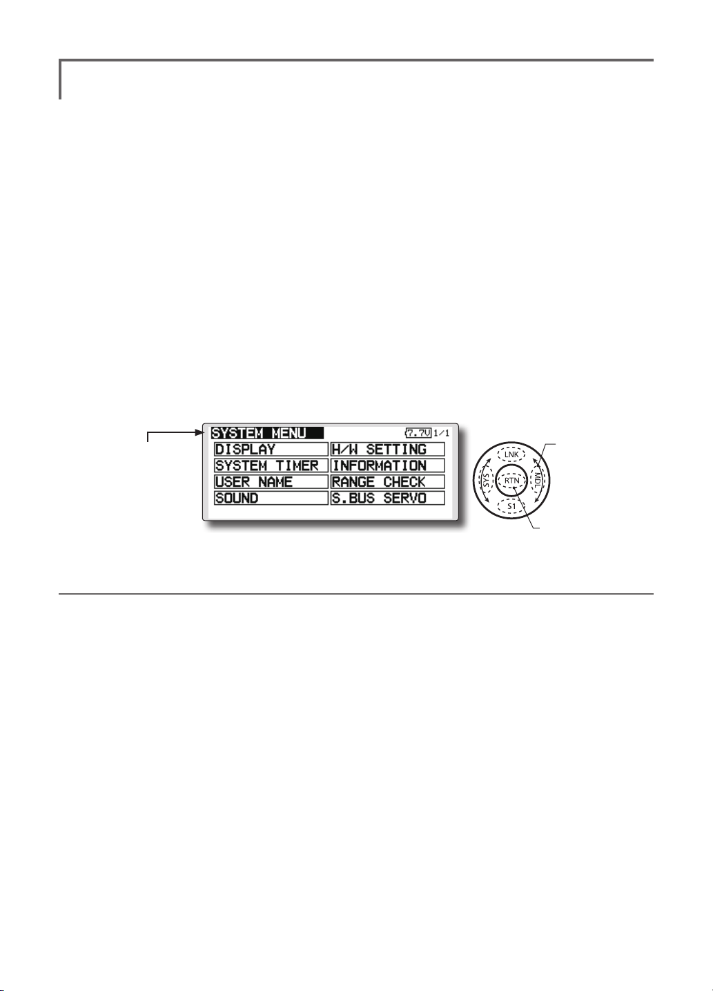
SYSTEM MENU
The System Menu sets up functions of the
transmitter: This does not set up any model data.
● Select [SYSTEM] at the home screen and call
the system menu shown below by touching
the RTN button.
● Scrolling the touch sensor to select the
function you want to set and call the setup
screen by touching the RTN button.
<SensorTouch™>
● Select the function name
and return to the System
menu by touching the
RTN button or pushing the
Home/Exit button.
Scrolling
● Moving cursor
●Access setup screen
System Menu functions table
[DISPLAY]: LCD contrast and back light adjustment.
[SYSTEM TIMER]: Resets the accumulated timer for each model.
[USER NAME]: User name registration.
[SOUND]: Various volume control and low battery setting.
[H/W SETTING]: H/W reverse, stick mode, stick calibration, and switch position.
[INFORMATION]: Displays the program version, SD card information, and language selection.
[RANGE CHECK]: A transmitting output is lowered and the check before a ight is carried out.
[S.BUS SERVO]: S.BUS servo setting.
<Functions of System Menu>
39
Page 2
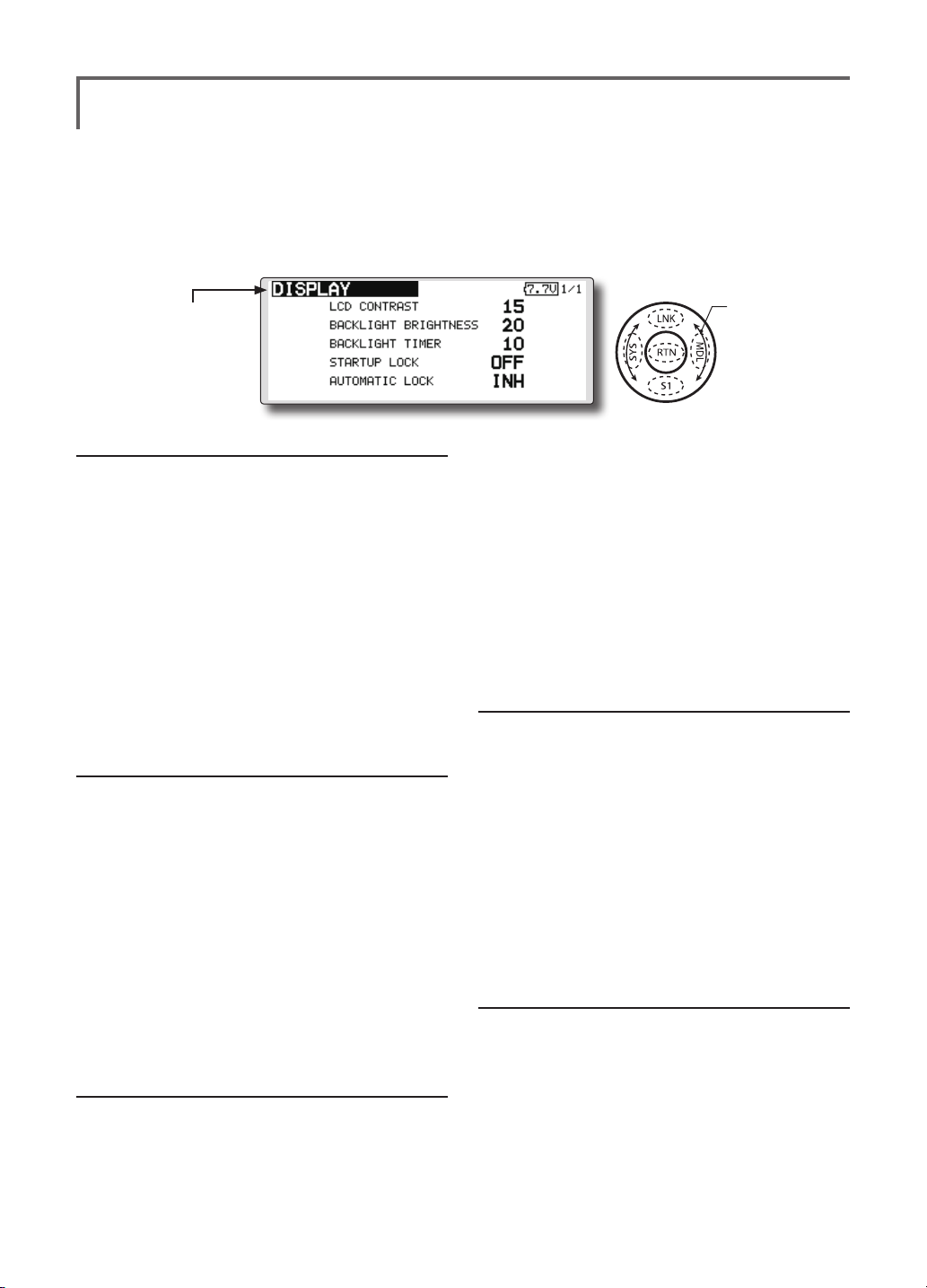
DISPLAY
LCD contrast adjustment and automatic key lock
The following LCD screen adjustments and auto
power off setting are possible:
● Backlighting brightness adjustment
● Backlighting off timer adjustment
● Automatic key lock setup
● Select [DISPLAY] at the system menu and call the setup
screen shown below by touching the RTN button.
● Select the function name
and return to the System
menu by touching the
RTN button or pushing the
Home/Exit button.
LCD contrast adjustment
1. Scrolling the touch sensor to select "LCD
CONTRAST" and touch the RTN button to
switch to the data input mode and adjust
the contrast by turning the touch sensor to
the left and right.
Setting range: (Lighter) 0 to 30 (Darker)
Initial value: 15
Touch the RTN button to end adjustment and
return to the cursol move mode.
*Adjust to the contrast while watching the screen display.
*When you want to reset the contrast to the initial state,
select "LCD CONTRAST" and touch the RTN button for 1
second.
light turns off after operating the touch
sensor.
Setting range: 10 to 240 sec (each 10 sec),
OFF (always on)
Initial value: 10 sec
*When you want to reset the value to the initial state, touch
the RTN button for one second.
2. Touch the RTN button to end adjustment and
return to the cursor mode.
*If the back light is on for a long time, consumption current
will increase.
Start lock
Auto Lock functions automatically when the
model changes or power is turned on.
Backlight brightness adjustment
1. Scrolling the touch sensor to select
"BACKLIGHT BRIGHTNESS" and touch the RTN
button to switch to the data input mode
and adjust the contrast by turning the touch
sensor to the left and right.
Setting range: (Darker) 0 to 30 (Lighter)
Initial value: 10
Touch the RTN button to end adjustment and
return to the cursol move mode.
*Adjust to the brightness while watching the screen display.
*When you want to reset the contrast to the initial state, select
"BACKLIGHT BRIGHTNESS" and touch the RTN button
for 1 second.
*To temporarily allow access to the T18SZ programming
press and hold the S1 button for one second. Please note,
the Auto Lock function timer will resume immediately once
again.
1. Select "STARTUP LOCK" and touch the RTN
button to switch to the data input mode and
adjust the ON or OFF by scrolling the touch
sensor.
Setting range: ON or OFF
Initial value: OFF
Automatic lock
Auto Lock functions automatically when there is
no operation from the HOME screen display for a
chosen number of seconds.
Back-light off-timer
1. Select "Back-light timer" and touch the RTN
button to switch to the data input mode and
adjust the back-light off-timer by scrolling the
touch sensor.
"OFF TIMER": Adjust the time when the back-
<Functions of System Menu>
40
1. Scrolling the touch sensor to select
"AUTOMATIC LOCK" and touch the RTN
button to switch to the data input mode and
adjust the time by turning the touch sensor to
the left and right.
Setting range: INH, 0 to 120 (s)
Initial value: INH
<SensorTouch™>
Scrolling
● Moving cursor
● Selecting mode
● Adjusting value
Page 3
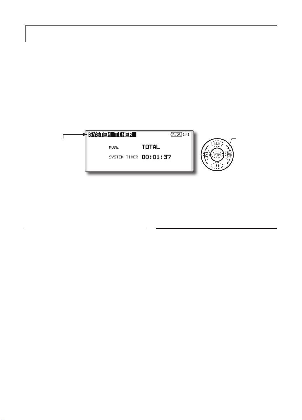
SYSTEM TIMER
Resets the accumulated timer.
This function resets the system timer displayed
on the home screen.
● T18SZ has two type system timers.
TOTAL timer: Displays the total accumulated
time on the transmitter from the last time the
timer was reset.
● Select [SYSTEM TIMER] at the system menu and
call the setup screen shown below by touching
the RTN button.
● Select the function name
and return to the System
menu by touching the
RTN button or pushing the
Home/Exit button.
MODEL timer: Displays the total accumulated
time on each model from the last time the
timer was reset.
● System timer displayed on the home screen
can be selected.
<SensorTouch™>
Scrolling
● Moving cursor
● Selecting mode
Timer selection
1.Move the cursor to the [MODE] item and
touch the RTN button to switch to the data
input mode.
Select the mode by scrolling the touch sensor
and touch the RTN button.
TOTAL: Displays the total timer on the home
screen.
MODEL timer: Displays the model timer on
the home screen.
Timer reset
1.Move the cursor to the [SYSTEM TIMER] item
and reset the timer to "00:00:00" by touching
the RTN button for 1 second. After reset, the
timer restarts from "00:00:00".
<Functions of System Menu>
41
Page 4
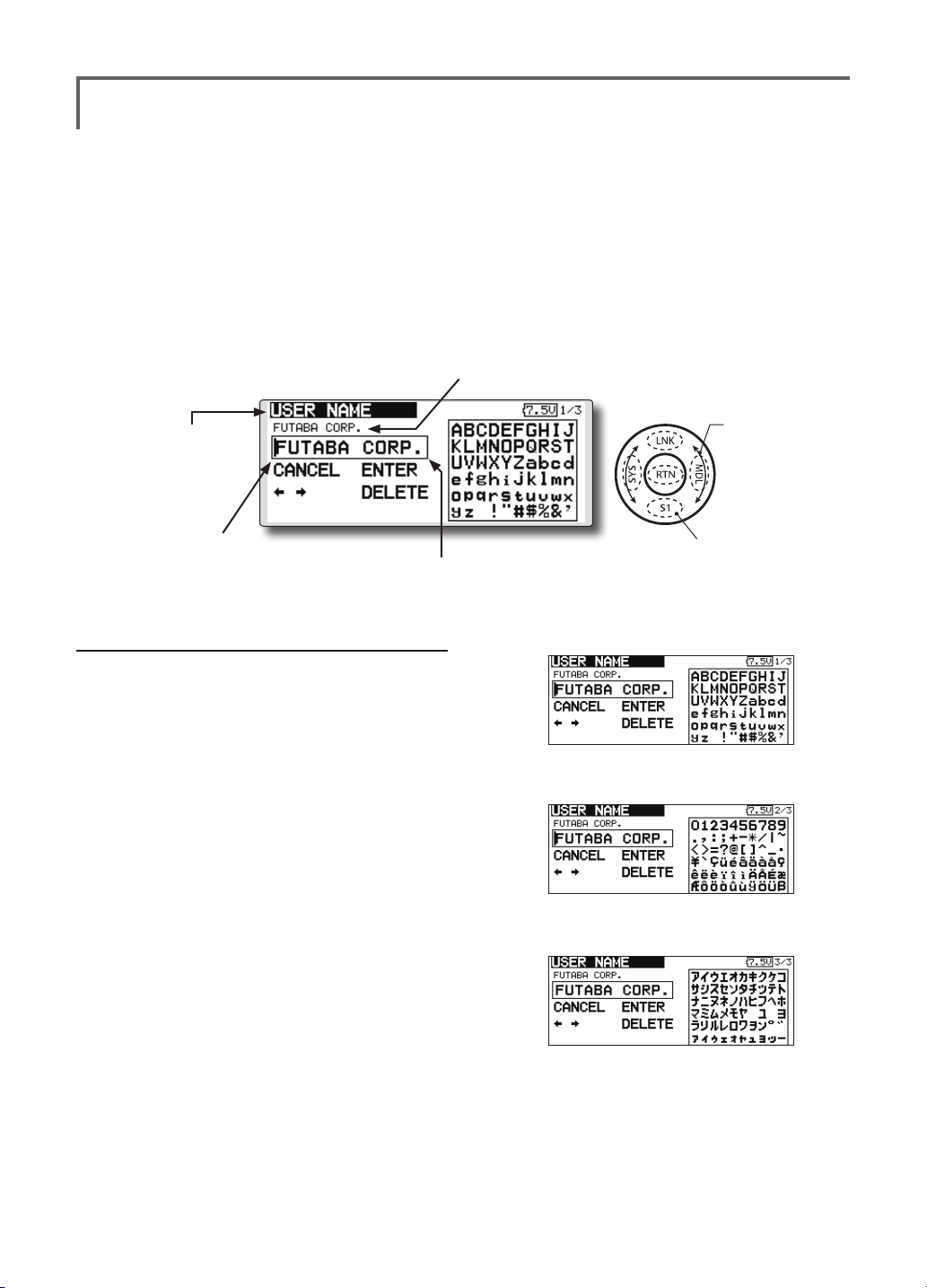
USER NAME
User name registration
This function registers the T18SZ user name.
*A name of up to 12 characters can be entered as the user
name. (Space is also counted as 1 character.)
● Select [USER NAME] at the system menu and call
the setup screen shown below by touching the
RTN button.
Current user name
● Select the function name
and return to the System
menu by touching the
RTN button or pushing the
Home/Exit button.
Cursor (blink)
Input box
User name registration
1. Change the user name as described below:
[Moving cursor in input box]
Select [←] or [→], and touch the RTN button.
[Deleting a character]
When [DELETE] is selected and the RTN button
is touched, the character immediately after
the cursor is deleted.
[Adding a character]
When a candidate character is selected
from the character list and the RTN button
is touched, that character is added at the
position immediately after the cursor.
*A name of up to 12 characters long can be entered as the
user name. (A space is also counted as 1 character.)
2. At the end of input, select [ENTER] and touch
the RTN button. (To terminate input and
return to the original state, select [CANCEL]
and touch the RTN button.)
<SensorTouch™>
Scrolling
● Moving cursor
● Push the S1 button to
call next page.
(Character list 1/3)
(Character list 2/3)
(Character list 3/3)
<Functions of System Menu>
42
Page 5
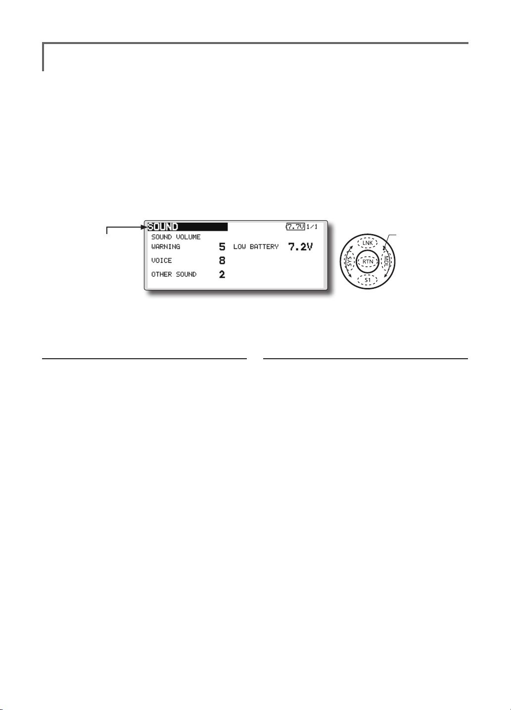
SOUND
Turns off the buzzer.
3 independent sound volumes: "WARNING",
"VOICE" and others, are available.
"LOW BATTERY" adjusts low battery alarm
voltage to match a battery.
● Select [SOUND] at the system menu and access
the setup screen shown below by touching the
RTN button.
● Select the function name
and return to the System
menu by touching the
RTN button or pushing the
Home/Exit button.
Sound volume operation
1. Move the cursor to the [WARNING][VOICE]
or [OTHER SOUND] item and touch the RTN
button to switch to the data input mode.
2. Select the volume by scrolling the touch
sensor.
*The display blinks.
3.Touch the RTN button.
<SensorTouch™>
Scrolling
● Moving cursor
● Adjusting value
● LOW BATTERY : 6.8V~7.6V
Low battery voltage operation
1. Move the cursor to the [LOW BATTERY] item
and touch the RTN button to voltage to the
data input mode.
2. Select the voltage by scrolling the touch
sensor. (6.8V-7.6V)
*The display blinks.
3.Touch the RTN button.
<Functions of System Menu>
43
Page 6
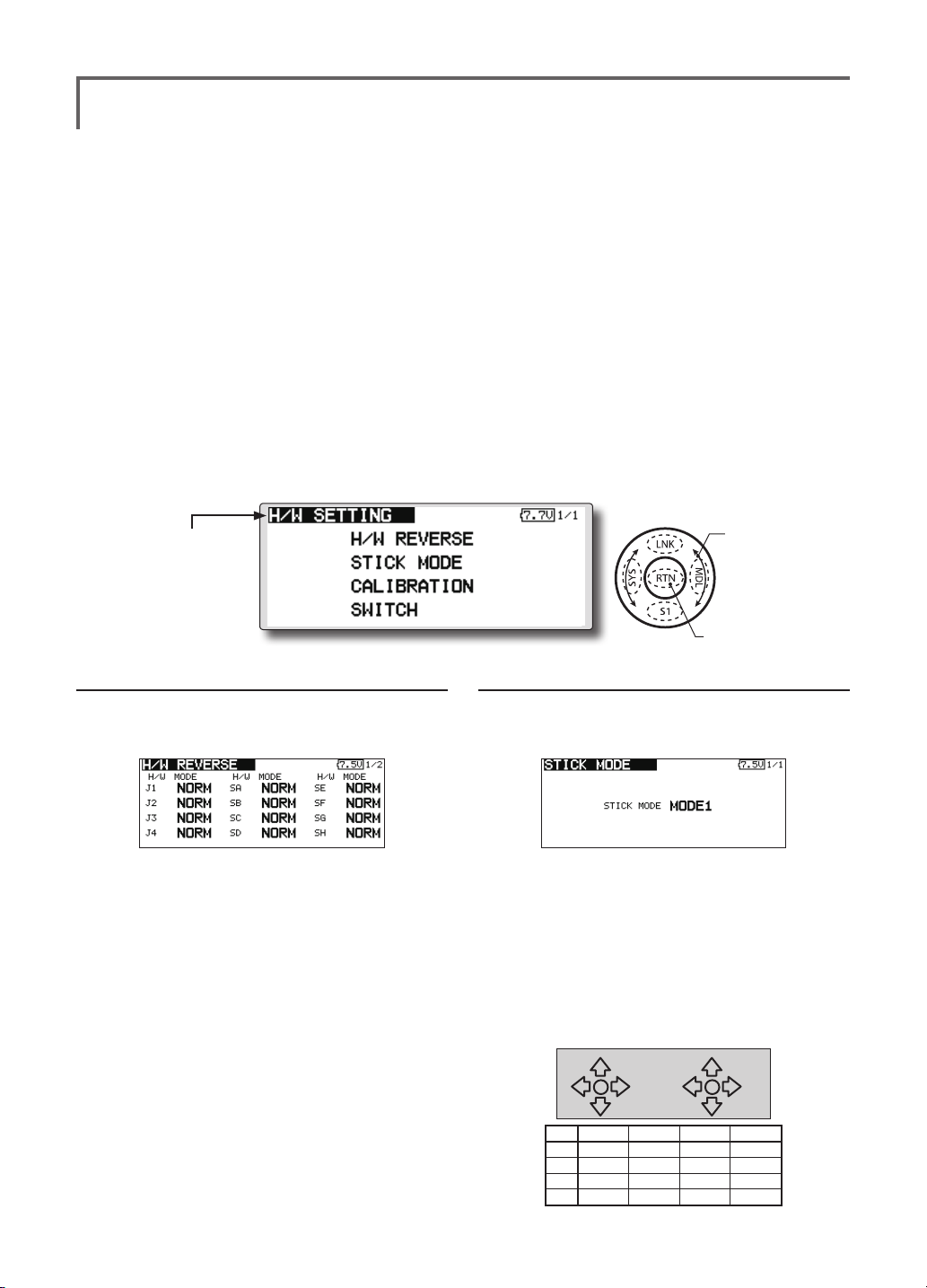
H/W SETTING
(J2)
(J3)
Hardware reverse and stick mode, stick calibration, switch position
H/W reverse
This function reverses the operation signal of the
sticks, switches, trimmer levers, and knobs.
Note: This setting reverses the actual operation
signal, but does not change the display of
the indicators on the display. Use the Normal
mode as long as there is no special reason to
use the Reverse mode.
Stick mode
This function changes the stick mode of
transmitter.
Note: This will not change the throttle ratchet,
etc. Those are mechanical changes that
must be done by a Futaba service center.
Note: After changing the mode, it is applied
when setting a new model. It is not applied
to an existing model.
Stick calibration
J1-J4 stick correction can be performed.
Note: It does not carry out, when there is no
necessity.
Switch
It inputs, when the kind of switch is changed or
it adds.
● Select [H/W SETTING] at the system menu and call the setup screen
shown below by touching the RTN button.
<SensorTouch™>
● Select the function name
and return to the System
menu by touching the
RTN button or pushing the
Home/Exit button.
Scrolling
● Moving cursor
●Access setup screen
Operation direction reversal method
1.Select [H/W REVERSE] and call the setup
screen shown below by touching the RTN
button.
2.Use the touch sensor to move the cursor to
the "MODE" item corresponding to the H/W
(hardware) you want to reverse and touch
the RTN button to switch to the data input
mode.
3. Change the mode by turning the touch
sensor to the left or right. The display blinks.
When the RTN button is touched, the
operation direction is reversed. (To terminate
mode change, turn the touch sensor or push
the S1 button.)
"NORM": Normal operation direction
"REV" : Operation direction is reversed.
<Functions of System Menu>
44
Operation direction reversal method
1.Select [STICK MODE] and call the setup
screen shown below by touching the RTN
button.
2. Use the touch sensor to move the cursor to
the "STICK MODE" item and touch the RTN
button to switch to the data input mode.
3. Change the mode by turning the touch
sensor to the left or right. The display blinks.
When the RTN button is touched, the stick
mode is changed. (To terminate mode
change, turn the touch sensor or push the S1
button.)
(J4)
Mode J1 J2 J3 J4
1 Aileron Throttle Elevator Rudder
2 Aileron Elevator Throttle Rudder
3 Rudder Throttle Elevator Aileron
4 Rudder Elevator Throttle Aileron
(J1)
Page 7

Stick calibration method
*J3 and J4 correction is described below. J1 and J2
corrections are performed using the same procedure.
1.Select [CALIBRATION] and access the setup
screen shown below by touching the RTN
button.
2.Move the cursor to the J3-J4 button and
touch the RTN button.
3.Move the J3 or J4 sticks to the neutral position
and press the RTN button for one second.
Operation switch setting method
1.Select [SWITCH] and call the setup screen
shown below by touching the RTN button.
2.Use the touch sensor to move the cursor to
the "SA-SJ" item corresponding to the switch
you want to change and touch the RTN
button to switch to the data input mode.
3. Change the "2Pos" or "3Pos" by turning the
touch sensor to the left or right. The display
blinks. It will decide, if the RTN button is
pushed. (To terminate mode change, turn
the touch sensor or push the S1 button.)
"3Pos": 3 position switch
"2Pos" : 2 position switch
4.Set the J3 and J4 sticks fully to the bottom
right and wait until the buzzer sounds.
5.Set the J3 and J4 sticks fully to the top left and
wait until the buzzer sounds.
6.The above completes the correction
operation. Operate and check if stick
correction was performed normally.
<Functions of System Menu>
45
Page 8
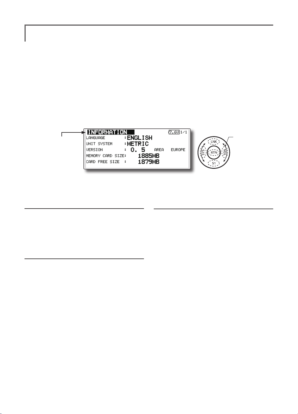
INFORMATION
Displays the program version, SD card information, and product ID.
The T18SZ system program version information,
SD card information (maximum and vacant number
of model data), and product ID are displayed on the
Information screen.
*When the SD card is not inserted, the SD card information is
not displayed.
● Select [INFORMATION] at the system menu and
call the setup screen shown below by touching
the RTN button.
● Select the function name
and return to the System
menu by touching the
RTN button or pushing the
Home/Exit button.
Information
"VERSION": T18SZ system program version
information
"MEMORY CARD SIZE": Maximum number of
model data (SD card)
"CARD FREE SIZE": Vacant number of model
data (SD card)
Language selection
1. Use the touch sensor to move the cursor to
the "LANGUAGE" item and touch the RTN
button to switch to the data input mode.
2. Change the language by turning the
touch sensor to the left or right. The display
blinks. When the RTN button is touched, the
language is changed. (To terminate mode
change, turn the touch sensor or push the S1
button.)
The language displayed in home, menu, and
setup screen is selectable.
Moreover, the unit of a telemetry display can
also be changed.
<SensorTouch™>
Scrolling
● Moving cursor
● Selecting mode
Unit system selection
1. Use the touch sensor to move the cursor to
the "UNIT SYSTEM" item and touch the RTN
button to switch to the data input mode.
2. Change the unit by turning the touch
sensor to the left or right. The display blinks.
When the RTN button is touched, the unit is
changed. (To terminate mode change, turn
the touch sensor or push the S1 button.)
<Functions of System Menu>
46
Page 9
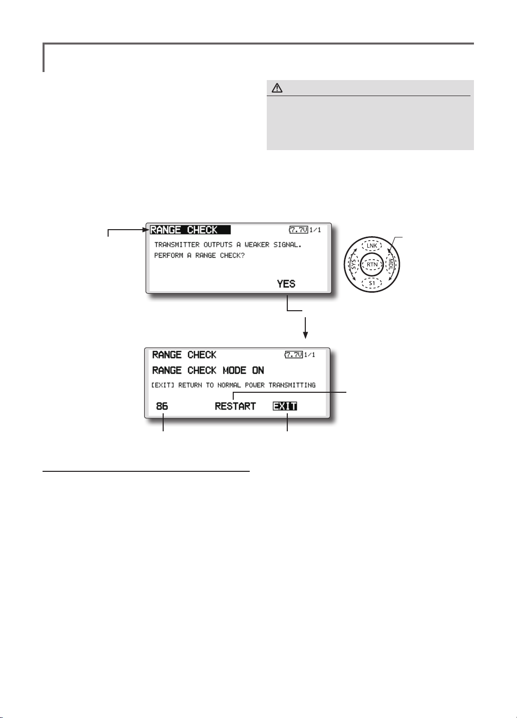
RANGE CHECK
Before a ight ground range check.
The 'range check mode' reduces the transmission
range of the radio waves to allow for a ground
range check.
*The range check mode, when activated, will continue for90
seconds unless the user exits this mode early. When the
progress bar reaches 90 second mark, the RF transmission
automatically returns to the normal operating power.
WARNING
Do not y in the range check mode.
Since the range of the radio waves is short, if the model
■
is too far from the transmitter, control will be lost and the
model will crash.
● Pushing [U.menu/Mon]key is continued. →Turn ON the transmitter's power switch. (First, a throttle
stick is made into a low position, and turns on a power supply.) It is displayed as "TRANSMIT?" .
"NO" is chosen and [RTN] is pushed.
● Select [RANGE CHECK] at the system menu and call the setup screen shown below by touching
the RTN button.
● Select the function name
and return to the System
menu by touching the
RTN button or pushing the
Home/Exit button.
<SensorTouch™>
Scrolling
● Moving cursor
● [Yes] is chosen and [RTN] is pushed.
● Remaining time of
RANGE CHECK MODE
Rotation Range Check method
1. Pushing [U.menu/Mon]key is continued.
Turn ON the transmitter's power switch.
→
(First, a throttle stick is made into a low
position, and turns on a power supply.)
It is displayed as "TRANSMIT?."
"NO" is chosen and [RTN] is pushed.
*For safety, the RANGE CHECK mode can not be selected
while the RF transmission is active.
2. In the system menu, choose the 'Range
Check' selection from the menu options.
3. The Range Check screen is displayed. To
activate the Range Check mode press
the [Yes] button. During the Range Check
period, the RF power is reduced to allow the
ground range tests to be performed.
4. The Range Check function automatically
exits after the 90 second time limit has
● Range Check mode
timer is returned to 90
● Range Check mode is
disabled
expired. The count down time is displayed on
the transmitter's screen. Should you complete
the range check before the 90 seconds has
pressed, press the [Exit] button.
*When the [RESTART] button is pressed, the range check
mode timer is returned to 90.
*Please note, upon expiration of the 90 seconds, or when
[Exit] is selected, the transmitter will automatically return to
the normal RF operation as noted on the display.
*Once the T18SZ is transmitting at full power, it is not
possible to enter the Range Check mode without first
switching the transmitter Off and back On. This has been
designed to prevent a modeler from inadvertently ying in
the Range Check mode.
5. When the [Exit] button is pressed, the Range
Check mode is disabled and the T18SZ will
begin transmitting at full power.
*After exiting the Range Check mode, the function cannot be
selected again. To select the Range Check mode again you
must cycle the transmitter power switch.
<Functions of System Menu>
47
Page 10
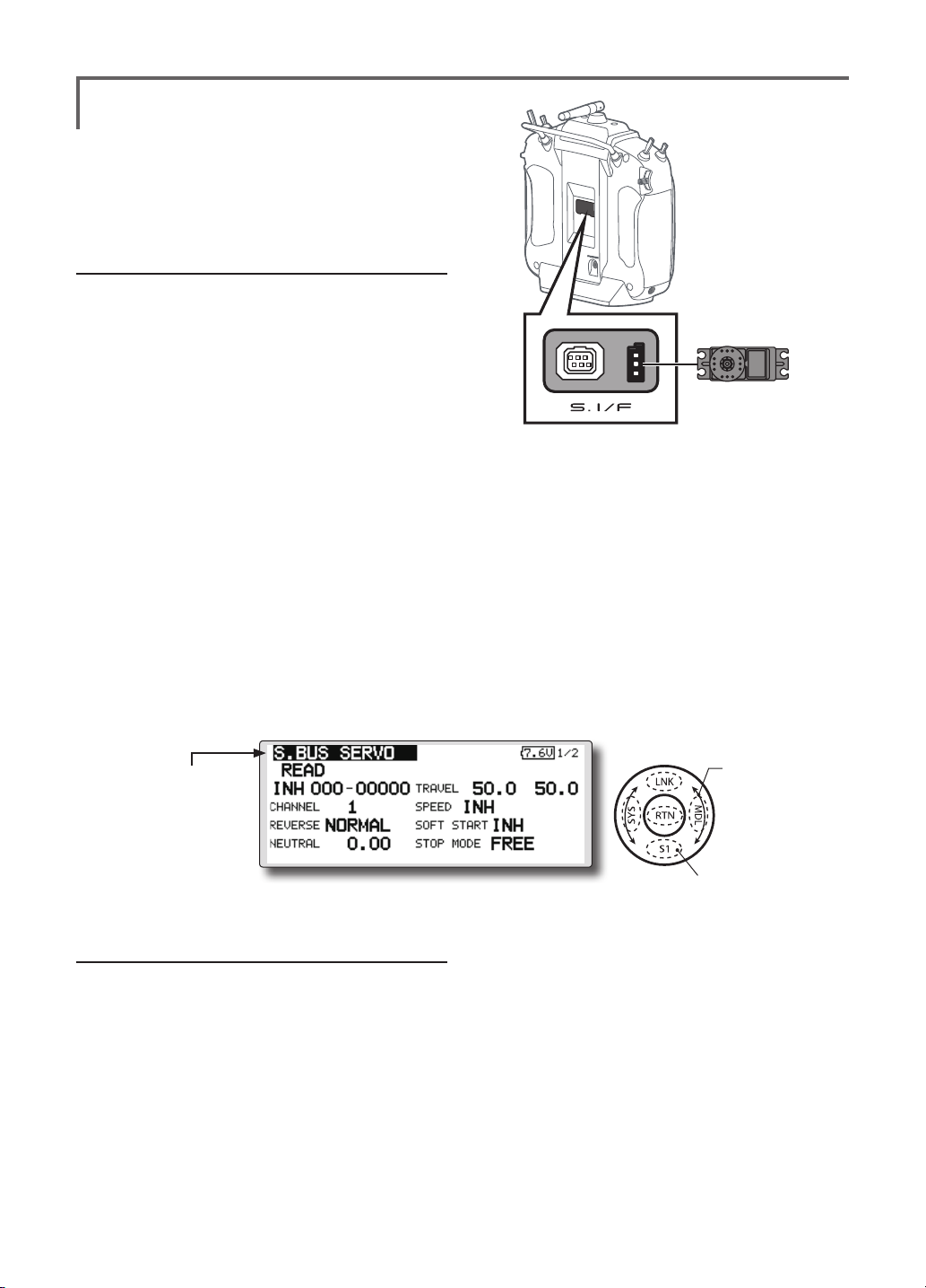
S.BUS Servo
S.BUS/S.BUS2 servo setting
An S.BUS/S.BUS2 servo can memorize
the channel and various settings itself. Servo
setting can be performed on the T18SZ screen
by wiring the servo as shown in the figure.
●Servo ID number
Individual ID numbers are memorized for your
S.BUS servos in your T18SZ. When a servo is
used (as shown at the right), the servo ID number is
automatically read by the transmitter.
If you use multiple S.BUS servos and do not
want to change the settings on all that are mounted
in a fuselage, only the desired servo in the group
can be set by entering the ID of that specic servo.
* With S.BUS/S.BUS2 servos of use, there are a function which
can be used, and an impossible function and a display screen
changes.
(Only the function which can be used by a servo is displayed.)
T18SZ
S.BUS/S.BUS2 servo
* After reading completion, with connection of the above
gure, if a stick is moved, the test of operation of the servo
can be operated and carried out.
*It is not necessary to carry out multiple connection of the
battery like a T18MZ/T14SG.
(It will damage, if it connects.)
*When you connect to a transmitter many servos which
consume many current, please use "Another power supply
HUB". And electric power is supplied to a servo with
another power supply.
● Call the following setting screen by pressing
the [S.BUS Servo] button in the System
Menu.
● Select the function name
and return to the System
menu by touching the
RTN button or pushing the
Home/Exit button.
Procedure for changing S.BUS/S.BUS2 servo
setting
1. Select [S.BUS Servo] of the System Menu.
2. Wire the servo as shown in the gure above.
3. Press [READ]. The ID and current setting of
that servo are displayed.
4. When multiple servos are connected change
[INH] at the right side of the ID number on the
screen to [ACT] and enter the ID of the servo
you want to set.
5. Set each item. (Please see the next page.)
6. Press [WRITE]. The settings are changed.
<SensorTouch™>
Scrolling
● Moving cursor
● Push the S1 button to
call next page.
<Functions of System Menu>
48
Page 11

S.BUS Servo Description of function of each parameter
*There are a function which can be used according to the kind of servo, and an impossible function.
• ID
Displays the ID of the servo whose parameters are to be read. It cannot be changed.
• Channel
Channel of the
• Reverse
The direction in which the servo rotates can be changed.
• Servo type
When “Retractable” is selected and the servo has been continuously stopped for 30 seconds, the dead
band expands and unnecessary hold current due to external force is eliminated. When a new control
signal enters, normal operation is resumed. When using the servo as a landing gear servo, select
“Retractable”. Also adjust the servo travel to match the landing gear movement range.
• Soft Start
Restricts operation in the specified direction the instant the power is turned on. By using this setting, the
first initial movement when the power is turned on slowly moves the servo to the specified position.
• Stop Mode
The state of the servo when the servo input signal is lost can be specified. The "Hold" mode setting holds
the servo in its last commanded position even if using AM or FM system.
• Smoother
This function changes smoothness of the servo operation relative to stick movement changes. Smooth
setting is used for normal flight. Select the "OFF" mode when quick operation is necessary such as 3D.
• Neutral Offset
The neutral position can be changed. When the neutral offset is large value, the servo's range of travel is
restricted on one side.
• Speed Control
Speeds can be matched by specifying the operating speed. The speed of multiple servos can be matched
without being affected by motor fluctuations. This is effective for load torques below the maximum torque.
However, note that the maximum speed will not be exceed what the servo is capable of even if the servos
operating voltage is increased.
• Dead band
The dead band angle at stopping can be specified.
[Relationship between dead band set value and servo operation]
Small → Dead band angle is small and the servo is immediately operated by a small signal change.
Large → Dead band angle is large and the servo does not operate at small signal changes.
(Note) If the dead band angle is too small, the servo will operate continuously and the current
consumption will increase and the life of the servo will be shortened.
• Travel Adjust
The left and right travels centered about the neutral position can be set independently.
• Boost
The minimum current applied to the internal motor when starting the servo can be set. Since a small
travel does not start the motor, it essentially feels like the dead band was expanded. The motor can be
immediately started by adjusting the minimum current which can start the motor.
[Relationship between boost set value and servo operation]
Small → Motor reacts to a minute current and operation becomes smooth.
Large → Initial response improves and output torque increases. However, if the torque is too large,
S.BUS
system assigned to the servo. Always assign a channel before use.
operation will become rough.
<Functions of System Menu>
49
Page 12

• Boost ON/OFF
OFF : It is the boost ON at the time of low-speed operation.(In the case of usual)
ON : It is always the boost ON.(When quick operation is hope)
• Damper
The characteristic when the servo is stopped can be set.
When smaller than the standard value, the characteristic becomes an overshoot characteristic. If the value
is larger than the standard value, the brake is applied before the stop position.
Especially, when a large load is applied, overshoot, etc. are suppressed by inertia and hunting may occur,
depending on the conditions. If hunting (phenomena which cause the servo to oscillate) occurs even
though the Dead Band, Stretcher, Boost and other parameters are suitable, adjust this parameter to a
value larger than the initial value.
[Relationship between damper set value and servo operation]
Small → When you want to overshoot. Set so that hunting does not occur.
Large → When you want to operate so that braking is not applied. However, it will feel like the servo
(Note) If used in the hunting state, not only will the current consumption increase, but the life of the servo
will also be shortened.
response has worsened.
• Stretcher
The servo hold characteristic can be set. The torque which attempts to return the servo to the target
position when the current servo position has deviated from the target position can be adjusted.
This is used when stopping hunting, etc., but the holding characteristic changes as shown below.
[Relationship between stretcher and servo operation]
Small → Servo holding force becomes weaker.
Large → Servo holding force becomes stronger.
(Note) When this parameter is large, the current consumption increases.
• Buzzer
When the power supply of a servo is previously turned on at the time of a power supply injection without
taking transmit of a transmitter, the buzzer sound of about 2.5 Hz continues sounding from a servo.
(Even when the transmit of a transmitter is taken out previously, a buzzer becomes until the signal of a
servo is outputted normally, but it is not unusual.)
The transmitter has been turned OFF ahead of a servo power supply→ The buzzer sound of about 1.25
Hz continues sounding as servo power supply end failure alarm.
(
Do not insert or remove the servo connector while the receiver power is ON. A buzzer may
sound by incorrect recognition.
Buzzer sound is generated by vibrating the motor of a servo.
*
Since current is consumed and a servo generates heat, please do not operate the number more than
needed or do not continue sounding a buzzer for a long time.
<Functions of System Menu>
50
)
Page 13
MODEL BASIC SETTING PROCEDURE
Airplane/glider basic setting procedure
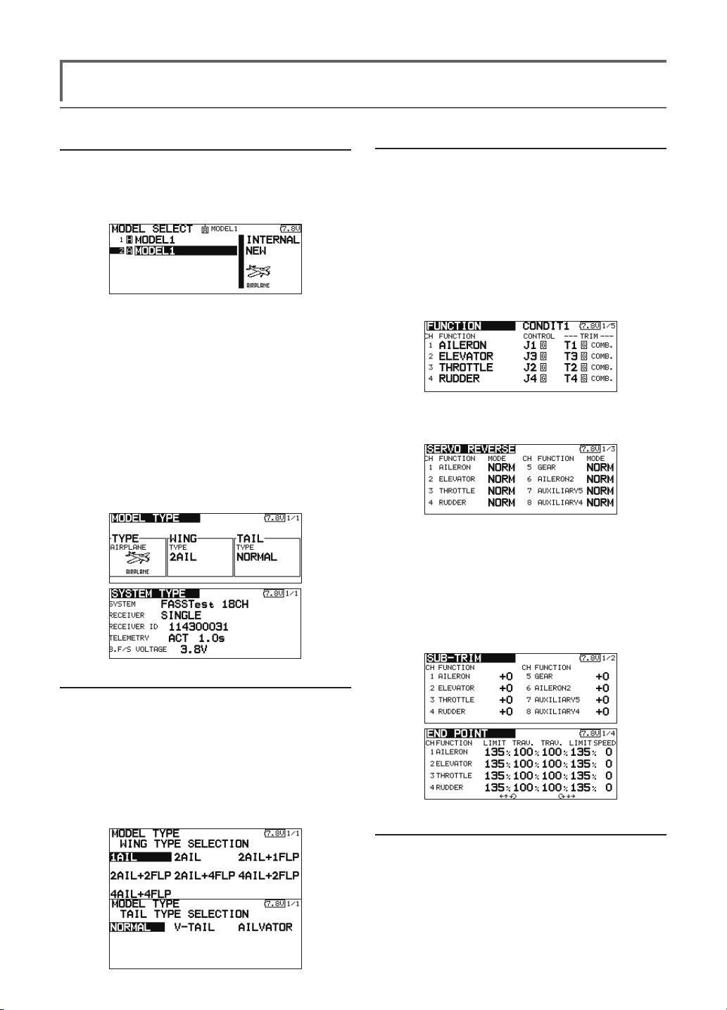
1. Model addition and call
Initial setting assigns 1 model to the T18SZ
transmitter. The Model Select function of the Linkage
Menu is used to add models and to select models which
are already set.
The data for up to 30 models can be saved to the
transmitter. Data can also be saved to the optional SD
card.
The currently selected model name is displayed
at the top of the screen. Before flying and before
changing any settings, always confirm the model
name.
When a new model is added, the Model type
select screen and System/Receiver ID setup screen
automatically appear. Please be aware that the
transmitter will stop transmitting when you change
the model.
3. Fuselage linkage
Connect the ailerons, elevators, throttle, rudder, etc.
in accordance with the model's instruction manual. For
a description of the connection method, see the Receiver
and Servos Connection.
Note: The channel assignment of the T18SZ is
different from that of our existing systems. Note
that even for the same "airplane model", when the
wing type and tail type are different, the channel
assignment may be different. (The channel assigned
to each function can be checked at the Function
menu of the Linkage Menu.)
● If the direction of the servo is incorrect, adjust
the direction with the Reverse function of the
Linkage Menu.
2. Model type selection
Select the model type matched to the aircraft with the
Model Type select function of the Linkage Menu. For an
airplane, select the model type from among the 2 types:
airplane and glider. After the wing type is selected the
tail type select screen is displayed. Select the tail type
matched to the aircraft.
There are 13 wing types and 3 tail types for airplane
and glider.
● Adjust the neutral position and control surface
angle with the linkage, and fine tune them
with the Sub Trim and End Point functions
(angle adjustment). To protect the linkage, a
limit position can also be set with the End Point
function. The End Point function can adjust the
amount of up/down and left/right movement,
limit, and servo speed of each channel.
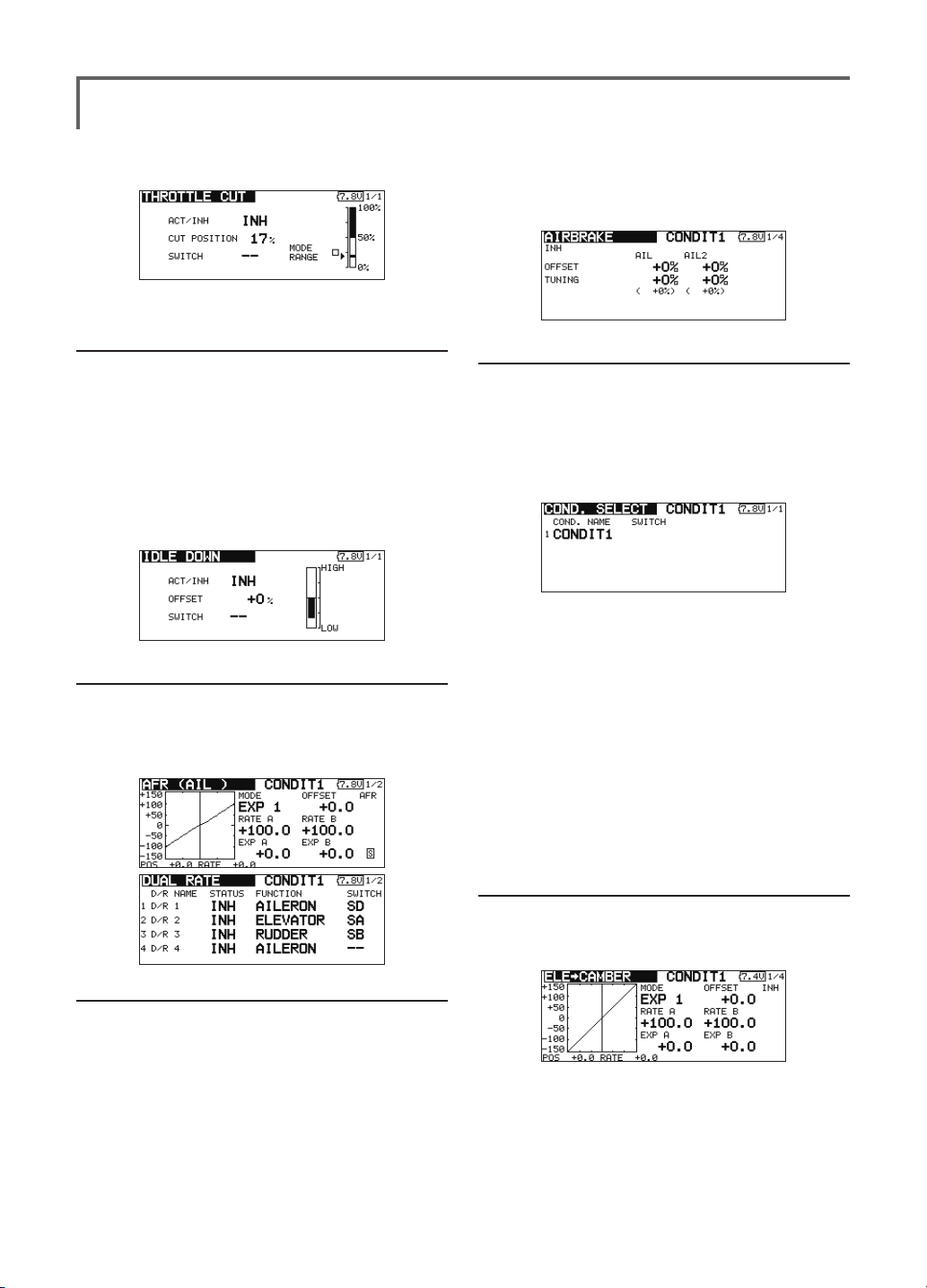
4. Throttle cut setting
Throttle cut can be performed with one touch by a
switch without changing the throttle trim position.
Set throttle cut with the Throttle Cut function of the
Linkage Menu. After activating the throttle cut function
and selecting the switch, adjust the throttle position so
that the carburetor becomes fully closed. For safety, the
<Model Basic Setting Procedure>
51
Page 14
throttle cut function operates the throttle stick in the 1/3
or less (slow side) position.
chosen. Trim amounts can be ne-tuned by setting a VR.
You can also set the Auto Mode, which will link Airbrake
to a stick, switch, or dial. A separate stick switch or dial
can also be set as the ON/OFF switch.
5. Idle down setting
The idling speed can be lowered with one touch by
a switch without changing the throttle trim position.
Perform this setting with the Idle Down function of the
Linkage Menu. After activating the Idle Down function
and selecting the switch, adjust the idle down speed. For
safety, the idle down function acts only when the throttle
stick is slow
*While the Throttle Cut function is in operation, the Idle
Down function does not work.
side.
6. AFR (D/R)
AFR function is used to adjust the throw and operation
curve of the stick, lever, and switch functions for each
flight condition. This is normally used after End Point
has dened the maximum throw directions.
8. Addition of ight conditions
The Condition Select function automatically allocates
the Condition 1 (CONDIT1) for each model. Condition 1
is the default condition and is the only one active when a
new model type is dened.
If you want to add ight conditions, please refer to a
description of the COND. SELECT function.
*The Condition 1 is always on, and remains on until other
conditions are activated by switches.
*When a new condition is added, the model data of the
Condition 1 is automatically copied to the new condition.
*You can set the model data of new condition in the switch
ON state. However, if the group mode (GROUP) was
selected in advance, the same data will be input at all the
conditions. Select the single mode (SINGLE) and adjust
only the condition you want to change. For Group/Single
mode switching, refer to the description at the back of this
manual.
*The Condition Delay can be programmed for each channel.
The Condition Delay is used to change the servo throw
smoothly when switching conditions.
7. Airbrake
This function is used when an air brake is necessary
when taking off or diving, etc.
The preset elevators and aps (camber ap, brake ap)
offset amount can be activated by a switch.
The offset amount of the aileron, elevator, and flap
servos can be adjusted as needed. Also the speed of the
aileron, elevator, and flap servos can be adjusted. (IN
side/OUT side) A delay can be set for each condition,
and a Cut switch which will turn OFF the delay can be
<Model Basic Setting Procedure>
52
9. When tailless wing model selected
Tailless wing elevator operation uses elevator to
camber mixing. This function cannot be performed at
initial setting.
Page 15
Helicopter basic setting procedure
This section outlines examples of use of the helicopter functions of the T18SZ. Adjust the actual values, etc. to
match the fuselage used.
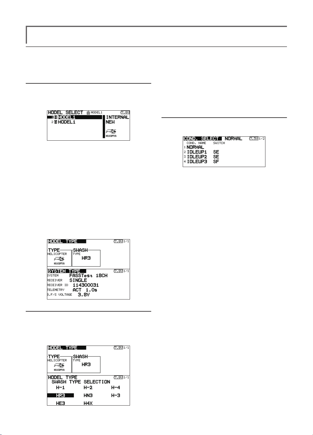
1. Model addition and call
Default setting assigns 1 model to the T18SZ. To
add new models or to call a model already set, use
the Model Select function of the Linkage Menu.
This is convenient when calling a model after
registering the model names in advance. (The data
of up to 30 models can be saved at the transmitter.
Data can also be saved to the optional SD card.)
The currently called model is displayed at the top
of the screen. Before flying and before changing
any settings, always conrm the model name.
When a new model is added, the Model Type
Select screen and Frequency/Modulation mode/
Receiver ID setup screen automatically appear.
Change, or check that they match the type,
frequency, and receiver type of the model used.
2. Model type and swash type selection
If a different model type is already selected,
select helicopter with the Model Type function of
the Linkage Menu, and then select the swash type
matched to the helicopter.
*The Model Type function automatically selects the
appropriate output channels, control functions, and mixing
functions for the chosen model type. Eight swash types are
available for helicopters.
*For a description of the swash type selection, refer to the
MODEL TYPE function.
3. Flight condition addition
The transmitter can install up to eight ight conditions
per model.
The Condition Select function automatically allocates
ve conditions for helicopter.
(Initial setting)
● NORMAL
● IDLE UP1 (SW-E)
● IDLE UP2 (SW-E)
● IDLE UP3 (SW-F)
●HOLD (SW-G)
Note: Since you may accidentally activate
the conditions that has not been setup
during flight and this could cause a crash,
delete the conditions not used.
*For a description of the condition deletion, refer to the
COND. SELECT function.
The NORMAL condition is always on, and remains on
until other conditions are activated by switches.
The priority is throttle hold/idle up 2/idle up 1/normal.
Throttle hold has the highest priority.
Add other conditions, as required.
The Condition Delay can be programmed for each
channel. The Condition Delay is used to change the servo
throw smoothly when switching conditions.
(General ight condition setting example)
● Normal: (Use initial setting conditions/operate
when switch OFF)
Use from engine starting to hovering.
● Idle up 1: (Operate at SW-E center)
Use in 540º stall turn, loop, rolling stall turn, and other
maneuvers.
● Idle up 2: (Operate at SW-E forward side)
Use in rolls.
● Throttle hold: (Operate at SW-G forward side)
Use in auto rotation.
<Model Basic Setting Procedure>
53
Page 16
4. Fuselage linkage
Connect the throttle rudder, aileron, elevator, pitch,
and other servos in accordance with the kit instruction
manual. For a description of the connection method, see
"Receiver and Servos Connection".
Note: The channel assignment of the T18SZ
is different from that of our existing systems.
(The channel assigned to each function can
be checked at the Function menu of the
Linkage Menu.)
● If the direction of operation of the servo
is incorrect, use the Reverse function of
the Linkage Menu. Also use the swash AFR
function in other than the H-1 mode.
● Adjust the direction of operation of the gyro.
(Gyro side function)
● Connect the throttle linkage so that the
carburetor can fully close at full trim throttle
cut.
● Adjust the neutral position at the linkage side
and ne tune with the Sub-Trim function and
End Point function (rudder angle adjustment).
To protect the linkage, a limit position can
also be set with the End Point function.
● Swash plate correction (Except H-1 mode)
*If any interactions are noticed, for a description of the
linkage correction function, please refer to the SWASH
function.
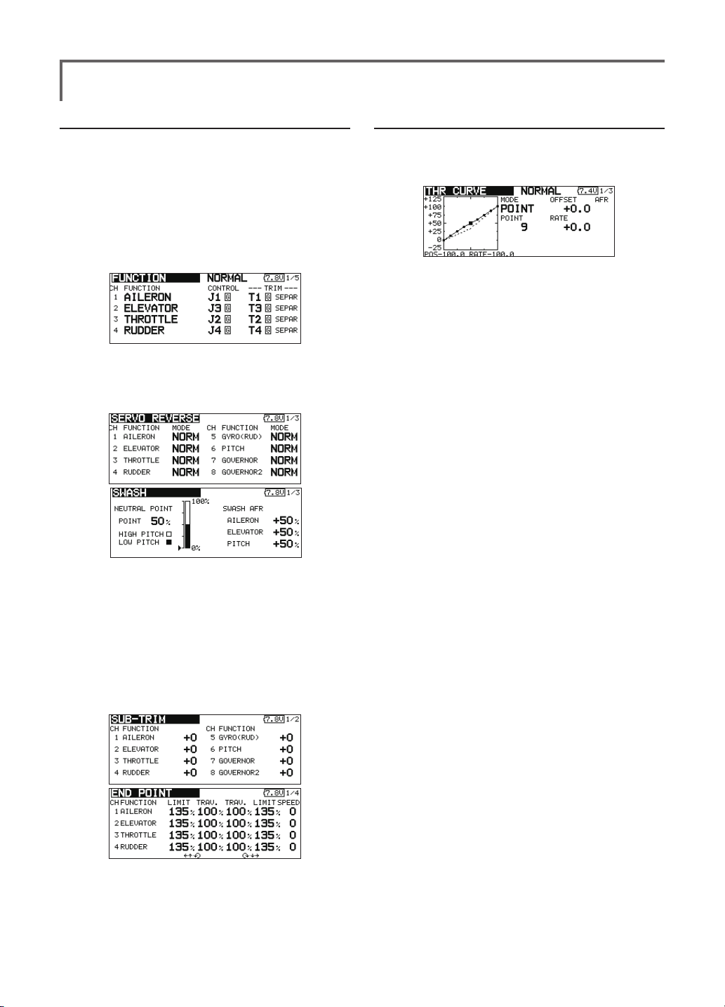
5. Throttle/Pitch curve setting
This function adjusts the throttle or pitch operation
curve in relation to the movement of the throttle stick for
each condition.
<Throttle curve setting example>
Call the throttle curve of each condition with the
condition select switch.
●Normal curve adjustment
Normal curve creates a basic throttle curve
centered near hovering. This curve is adjusted
together with the pitch curve (Normal) so that the
engine speed is constant and up/down control is
easiest.
●Idle up curve adjustment
The low side Throttle curve creates a curve
matched for aerobatics (loop, roll, 3D, etc.).
●Throttle hold curve adjustment
The curve is not used when performing auto rotation
dives.
Conrm that the rate of the slowest position (0%) of
the stick is 0% (initial setting).
<Example of pitch curve setting>
Call the pitch curve of each condition with the
condition select switch.
●Pitch curve (Normal)
Make the pitch at hovering approximately +5º~6º.
Set the pitch at hovering with the stick position at
the 50% point as the standard.
*Stability at hovering may be connected to the throttle curve.
Adjustment is easy by using the hovering throttle function
and hovering pitch function together.
●Pitch curve (Idle up 1)
The idle up 1 pitch curve function creates a curve
matched to airborne ight.
Set to -7º~+12º as standard.
●Pitch curve (Idle up 2)
The high side pitch setting is less than idle up 1.
The standard is +8º.
●Pitch curve (Hold)
At auto rotation, use the maximum pitch at both
the high and low sides.
[Pitch angle setting example]
Throttle hold: -7º~+12
º
<Model Basic Setting Procedure>
54
Page 17
6. AFR (D/R)
AFR (D/R) function is used to adjust the throw
and operation curve of aileron, elevator and rudder
for each condition.
*For throttle and pitch curve settings, refer to the above-
mentioned "Throttle/Pitch curve setting"
This is normally used after End Point has dened
the maximum throw directions.
7. Gyro sensitivity and mode switching
The gyro sensitivity and mode switching function is
dedicated gyro mixing of the Model Menu, and can be
set for each condition.
●Normal condition (hovering): Gyro sensitivity
maximum
●Idle up 1/Idle up 2/Throttle hold: Gyro
sensitivity minimum
●However, at auto rotation of a tail-driven
helicopter, this function may not have any
effect at high gyro sensitivity.
do not use Pitch to RUD mixing.
Call the Pitch to RUD mixing function from the
Model Menu, and set the curve for each condition. (At
initial setting, this function is in the "INH" state. To use
it, set it to the "ON" state.)
<Setting example>
Call the mixing curve of each condition with the
condition select switch.
1. A curve setting example is shown below.
●Pitch to RUD mixing curve (Normal)
Use the hovering system and set this curve to
match take off and landing and vertical climb at
a constant speed.
*For this curve, use the initial setting [EXP1] curve type.
●Pitch to RUD mixing (Idle up 1)
Use this curve in 540º stall turn, loop, and rolling
stall turn, and adjust it so the fuselage is facing
straight ahead when heading into the wind.
*For this curve, [EXP1] curve type can be used and the entire
curve can be lowered with the [Offset] function.
●Pitch to RUD mixing (Hold)
This function is set so that the fuselage is facing
straight ahead at straight line auto rotation. The
pitch of the tail rotor becomes nearly 0º.
*For this curve, [EXP1] curve type can be used and the entire
curve can be lowered with the [Offset] function.
●Other settings
The mixing rise characteristic at pitch operation
can be adjusted. An acceleration function which
temporarily increases and decreases the mixing
amount can be set.
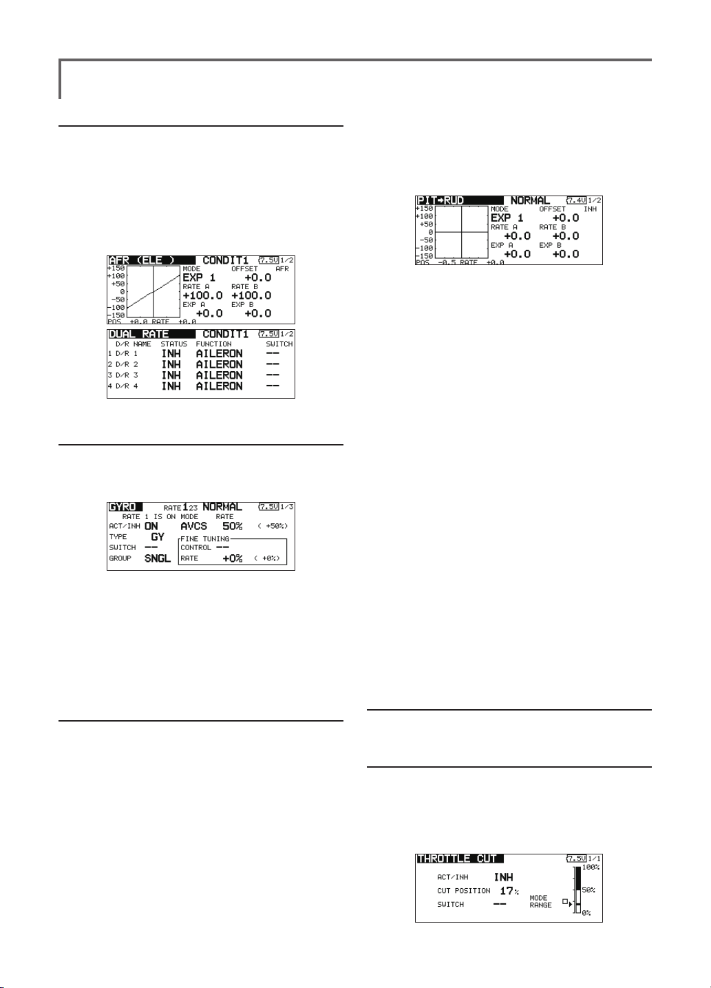
8. Pitch to RUD mixing setting
Note: When using a GY601, GY502, GY401,
or other heading hold gyro, this Pitch to RUD
mixing should not be used. The reaction
torque is corrected at the gyro side. When
operating the gyro in the AVCS mode, the
mixed signal will cause neutral deviation
symptoms and the gyro will not operate
normally.
Use this function when you want to suppress the
torque generated by the changes in the pitch and speed of
the main rotor during pitch operation. Adjust it so that the
nose does not swing in the rudder direction. However,
when using a heading hold gyro like those shown below,
9. Throttle hold setting
*If throttle hold is necessary, please refer to the THR HOLD
function.
10. Throttle cut setting
Throttle cut provides an easy way to stop the engine,
by flipping a switch with the throttle stick at idle. The
action is not functional at high throttle to avoid accidental
dead sticks. The switch’s location and direction must be
chosen, as it defaults to NULL.
<Model Basic Setting Procedure>
55
Page 18
*With throttle stick at idle, adjust the cut position until
the engine consistently shuts off, but throttle linkage is
not binding.
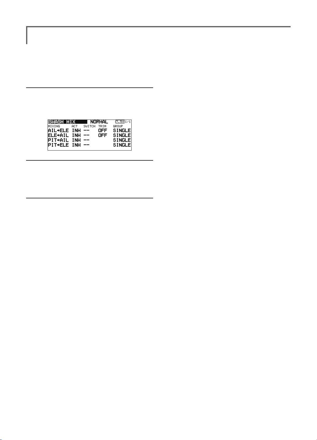
11. Swash Mix corrects aileron, elevator and
pitch interaction
The swash mix function is used to correct the swash
plate in the aileron (Left/Right Cyclic) and elevator
(Forward/Aft Cyclic) direction corresponding to each
operation of each condition.
12. Throttle mixing setting
*If throttle mixing is necessary for a compensation for
slowing of engine speed caused by swash plate operation
during aileron or elevator operation, please refer to the
THROTTLE MIX function.
13. Other special mixings
●Pitch to Needle mixing
This mixing is used with engines with a construction
which allows needle control during ight (fuel-air
mixture adjustment). A needle curve can be set.
The needle servo rise characteristics at throttle
stick acceleration/deceleration operation can be
adjusted. (Acceleration function)
●Governor mixing
This mixing is dedicated governor mixing when a
governor is used. Up to 3 rates (speeds) can be
switched for each condition.
<Model Basic Setting Procedure>
56
Page 19

<Model Basic Setting Procedure>
57
Page 20

Servo connection by model type
The T18SZ transmitter channels are automatically assigned for optimal combination according to the type selected
with the Model Type function of the Linkage Menu. The channel assignment (initial setting) for each model type is
shown below. Connect the receiver and servos to match the type used.
*The set channels can be checked at the Function screen of the Linkage Menu. The channel assignments can also be changed.
For more information, read the description of the Function menu.
Airplane/glider/motor glider
●Airplane and V tail
CH of each
RX
CH
Airplane
1 Aileron Aileron Aileron Aileron Aileron Aileron Aileron Aileron Aileron Aileron Aileron Aileron
2 Elevator Elevator Elevator Elevator Elevator Elevator Elevator Elevator Elevator Elevator Elevator Elevator
3 Throttle Motor AUX7 Throttle Motor AUX7 Throttle Motor AUX7 Throttle Motor AUX7
4 Rudder Rudder Rudder Rudder Rudder Rudder Rudder Rudder Rudder Rudder Rudder Rudder
5 Gear AUX6 AUX6 Gear AUX6 AUX6 Gear AUX6 AUX6 Aileron2 Aileron2 Aileron2
6 Airbrake Airbrake Airbrake Aileron2 Aileron2 Aileron2 Aileron2 Aileron2 Aileron2 Flap Flap Flap
7 AUX5 AUX5 AUX5 AUX5 AUX5 AUX5 Flap Flap Flap Flap2 Flap2 Flap2
8 AUX4 AUX4 AUX4 AUX4 AUX4 AUX4 AUX5 AUX5 AUX5 Gear AUX6 AUX6
9 AUX3 AUX3 AUX3 AUX3 AUX3 AUX3 AUX4 AUX4 AUX4 AUX5 AUX5 AUX5
10 AUX2 AUX2 AUX2 AUX2 AUX2 AUX2 AUX3 AUX3 AUX3 AUX4 AUX4 AUX4
11 AUX1 AUX1 AUX1 AUX1 AUX1 AUX1 AUX2 AUX2 AUX2 AUX3 AUX3 AUX3
12 AUX1 AUX1 AUX1 AUX1 AUX1 AUX1 AUX1 AUX1 AUX1 AUX2 AUX2 AUX2
13 AUX1 AUX1 AUX1 AUX1 AUX1 AUX1 AUX1 AUX1 AUX1 AUX1 AUX1 AUX1
14 AUX1 AUX1 AUX1 AUX1 AUX1 AUX1 AUX1 AUX1 AUX1 AUX1 AUX1 AUX1
15 AUX1 AUX1 AUX1 AUX1 Buttery Buttery AUX1 Buttery Buttery AUX1 Buttery Buttery
16 AUX1 AUX1 AUX1 Camber Camber Camber Camber Camber Camber Camber Camber Camber
DG1 SW SW SW SW SW SW SW SW SW SW SW SW
DG2 SW SW SW SW SW SW SW SW SW SW SW SW
1AIL 2AIL 2AIL+1FLAP 2AIL+2FLAP
Glider
EP EP EP EP
Airplane
Glider
Airplane
Glider
Airplane
Glider
system
FASST 7CH
S-FHSS
The output
FASSTest 12CH
FASSTest 18CH FASST MULT
RX
CH
1 Aileron Aileron Aileron Aileron Aileron Aileron Aileron Aileron Aileron
2 Elevator Elevator Elevator Elevator Elevator Elevator Elevator Elevator Elevator
3 Throttle Rudder Rudder Throttle Rudder Rudder Throttle Rudder Rudder
4 Rudder Aileron2 Aileron2 Rudder Aileron2 Aileron2 Rudder Aileron2 Aileron2
5 Gear Flap Flap Gear Aileron3 Aileron3 Gear Aileron3 Aileron3
6 Aileron2 Flap2 Flap2 Aileron2 Aileron4 Aileron4 Aileron2 Aileron4 Aileron4
7 Flap Flap3 Flap3 Aileron3 Flap
8 Flap2 Flap4 Flap4
9 Flap3 Motor AUX7
10 Flap4 AUX6 AUX6 Flap2 AUX6 AUX6
11 AUX5 AUX5 AUX5 AUX5 AUX5 AUX5 Flap3 Motor AUX7
12 AUX4 AUX4 AUX4 AUX4 AUX4 AUX4 Flap4 AUX6 AUX6
13 AUX3 AUX3 AUX3 AUX3 AUX3 AUX3 AUX5 AUX5 AUX5
14 AUX2 AUX2 AUX2 AUX2 AUX2 AUX2 AUX4 AUX4 AUX4
15 AUX1 Buttery Buttery AUX1 Buttery Buttery AUX3 Buttery Buttery
16 Camber Camber Camber Camber Camber Camber Camber Camber Camber
DG1 SW SW SW SW SW SW SW SW SW
DG2 SW SW SW SW SW SW SW SW SW
2AIL+4FLAP 4AIL+2FLAP 4AIL+4FLAP
Airplane
<Model Basic Setting Procedure>
58
Glider
EP EP EP
Airplane
Aileron4 Flap2 Flap2 Aileron4 Flap2 Flap2
Flap Motor
Glider
Airplane
Flap
Aileron3 Flap
AUX7
Flap Flap3 Flap3
Flap2 Flap4 Flap4
Glider
Flap
CH of each
system
FASST 7CH
S-FHSS
FASSTest 12CH
The output
FASSTest 18CH FASST MULT
Page 21

●Ailevator
RX
CH
Airplane
1 Aileron Aileron Aileron Aileron Aileron Aileron Aileron Aileron Aileron Aileron Aileron Aileron
2 Elevator Elevator Elevator Elevator Elevator Elevator Elevator Elevator Elevator Elevator Elevator Elevator
3 Throttle Motor AUX7 Throttle Motor AUX7 Throttle Motor AUX7 Throttle Motor AUX7
4 Rudder Rudder Rudder Rudder Rudder Rudder Rudder Rudder Rudder Rudder Rudder Rudder
5 Gear AUX6 AUX6 Gear AUX6 AUX6 Elevator2 Elevator2 Elevator2 Elevator2 Elevator2 Elevator2
6 Airbrake Airbrake Airbrake Aileron2 Aileron2 Aileron2 Aileron2 Aileron2 Aileron2 Aileron2 Aileron2 Aileron2
7 Elevator2 Elevator2 Elevator2 Elevator2 Elevator2 Elevator2 Flap Flap Flap Flap Flap Flap
8 AUX5 AUX5 AUX5 AUX5 AUX5 AUX5 Gear AUX6 AUX6 Flap2 Flap2 Flap2
9 AUX4 AUX4 AUX4 AUX4 AUX4 AUX4 AUX5 AUX5 AUX5 Gear AUX6 AUX6
10 AUX3 AUX3 AUX3 AUX3 AUX3 AUX3 AUX4 AUX4 AUX4 AUX5 AUX5 AUX5
11 AUX2 AUX2 AUX2 AUX2 AUX2 AUX2 AUX3 AUX3 AUX3 AUX4 AUX4 AUX4
12 AUX1 AUX1 AUX1 AUX1 AUX1 AUX1 AUX2 AUX2 AUX2 AUX3 AUX3 AUX3
13 AUX1 AUX1 AUX1 AUX1 AUX1 AUX1 AUX1 AUX1 AUX1 AUX2 AUX2 AUX2
14 AUX1 AUX1 AUX1 AUX1 AUX1 AUX1 AUX1 AUX1 AUX1 AUX1 AUX1 AUX1
15 AUX1 AUX1 AUX1 AUX1 Buttery Buttery AUX1 Buttery Buttery AUX1 Buttery Buttery
16 AUX1 AUX1 AUX1 Camber Camber Camber Camber Camber Camber Camber Camber Camber
DG1 SW SW SW SW SW SW SW SW SW SW SW SW
DG2 SW SW SW SW SW SW SW SW SW SW SW SW
RX
CH
Airplane
1 Aileron Aileron Aileron Aileron Aileron Aileron Aileron Aileron Aileron
2 Elevator Elevator Elevator Elevator Elevator Elevator Elevator Elevator Elevator
3 Throttle Motor AUX7 Throttle Motor AUX7 Throttle Motor AUX7
4 Rudder Rudder Rudder Rudder Rudder Rudder Rudder Rudder Rudder
5 Elevator2 Elevator2 Elevator2 Elevator2 Elevator2 Elevator2 Elevator2 Elevator2 Elevator2
6 Aileron2 Aileron2 Aileron2 Aileron2 Aileron2 Aileron2 Aileron2 Aileron2 Aileron2
7 Flap Flap Flap Aileron3 Aileron3 Aileron3 Aileron3 Aileron3 Aileron3
8 Flap2 Flap2 Flap2 Aileron4 Aileron4
9 Flap3 Flap3 Flap3
10 Flap4 Flap4 Flap4
11 Gear AUX6 AUX6 Gear AUX6 AUX6 Flap3 Flap3
12 AUX5 AUX5 AUX5 AUX5 AUX5 AUX5 Flap4 Flap4 Flap4
13 AUX4 AUX4 AUX4 AUX4 AUX4 AUX4 Gear AUX6 AUX6
14 AUX3 AUX3 AUX3 AUX3 AUX3 AUX3 AUX5 AUX5 AUX5
15 AUX2 Buttery Buttery AUX2 Buttery Buttery AUX4 Buttery Buttery
16 Camber Camber Camber Camber Camber Camber Camber Camber Camber
DG1 SW SW SW SW SW SW SW SW SW
DG2 SW SW SW SW SW SW SW SW SW
1AIL 2AIL 2AIL+1FLAP 2AIL+2FLAP
Glider
EP EP EP EP
Airplane
2AIL+4FLAP 4AIL+2FLAP 4AIL+4FLAP
Glider
EP EP EP
Airplane
Flap Flap Flap Flap Flap Flap
Flap2 Flap2
Glider
Glider
Aileron4
Airplane
Airplane
Aileron4 Aileron4
Flap2
Flap2 Flap2 Flap2
Glider
Glider
Aileron4
Flap3
Airplane
CH of each
system
FASST 7CH
S-FHSS
FASSTest 12CH
The output
Glider
FASSTest 18CH FASST MULT
CH of each
system
FASST 7CH
S-FHSS
FASSTest 12CH
The output
FASSTest 18CH FASST MULT
<Model Basic Setting Procedure>
59
Page 22

●Tailless wing
RX
CH
Airplane
1 Aileron Aileron Aileron Aileron Aileron Aileron Aileron Aileron Aileron
2 AUX4 AUX4 AUX4 AUX4 AUX4 AUX4 AUX4 AUX4 AUX4
3 Throttle Motor AUX7 Throttle Motor AUX7 Throttle Motor AUX7
4 Rudder Rudder Rudder Rudder Rudder Rudder Rudder Rudder Rudder
5 Gear AUX6 AUX6 Gear AUX6 AUX6 Aileron2 Aileron2 Aileron2
6 Aileron2 Aileron2 Aileron2 Aileron2 Aileron2 Aileron2 Flap Flap Flap
7 AUX5 AUX5 AUX5 Flap Flap Flap Flap2 Flap2 Flap2
8 AUX3 AUX3 AUX3 AUX5 AUX5 AUX5 Gear AUX6 AUX6
9 AUX2 AUX2 AUX2 AUX3 AUX3 AUX3 AUX5 AUX5 AUX5
10 AUX1 AUX1 AUX1 AUX2 AUX2 AUX2 AUX3 AUX3 AUX3
11 AUX1 AUX1 AUX1 AUX1 AUX1 AUX1 AUX2 AUX2 AUX2
12 AUX1 AUX1 AUX1 AUX1 AUX1 AUX1 AUX1 AUX1 AUX1
13 AUX1 AUX1 AUX1 AUX1 AUX1 AUX1 AUX1 AUX1 AUX1
14 AUX1 AUX1 AUX1 AUX1 Buttery Buttery AUX1 Buttery Buttery
15 Camber Camber Camber Camber Camber Camber Camber Camber Camber
16 Elevator Elevator Elevator Elevator Elevator Elevator Elevator Elevator Elevator
DG1 SW SW SW SW SW SW SW SW SW
DG2 SW SW SW SW SW SW SW SW SW
2AIL 2AIL+1FLAP 2AIL+2FLAP
Glider
EP EP EP
Airplane
Glider
Airplane
Glider
CH of each
system
FASST 7CH
S-FHSS
FASSTest 12CH
The output
FASSTest 18CH FASST MULT
RX
CH
1 Aileron Aileron Aileron Aileron Aileron Aileron Aileron Aileron Aileron
2 Aileron2 Aileron2 Aileron2 Aileron2 Aileron2 Aileron2 Aileron2 Aileron2 Aileron2
3 Throttle Motor AUX7 Throttle Motor
4 Rudder Rudder Rudder Rudder Rudder Rudder Rudder Rudder Rudder
5 Flap Flap Flap Aileron3 Aileron3 Aileron3 Aileron3 Aileron3 Aileron3
6 Flap2 Flap2 Flap2 Aileron4 Aileron4 Aileron4 Aileron4 Aileron4 Aileron4
7 Flap3 Flap3 Flap3 Flap
8 Flap4 Flap4 Flap4 Flap2 Flap2 Flap2 Flap2 Flap2 Flap2
9 AUX4 AUX4 AUX4 AUX4 AUX4 AUX4
10 Gear AUX6 AUX6 Gear AUX6 AUX6 Flap4 Flap4 Flap4
11 AUX5 AUX5 AUX5 AUX5 AUX5 AUX5 AUX4 AUX4 AUX4
12 AUX3 AUX3 AUX3 AUX3 AUX3 AUX3 Gear AUX6 AUX6
13 AUX2 AUX2 AUX2 AUX2 AUX2 AUX2 AUX5 AUX5 AUX5
14 AUX1 Buttery Buttery AUX1 Buttery Buttery AUX3 Buttery Buttery
15 Camber Camber Camber Camber Camber Camber Camber Camber Camber
16 Elevator Elevator Elevator Elevator Elevator Elevator Elevator Elevator Elevator
DG1 SW SW SW SW SW SW SW SW SW
DG2 SW SW SW SW SW SW SW SW SW
2AIL+4FLAP 4AIL+2FLAP 4AIL+4FLAP
Airplane
Glider
EP EP EP
Airplane
Flap
Glider
AUX7
Flap
Airplane
Throttle Motor
Flap Flap
Flap3 Flap3 Flap3
Glider
AUX7
Flap
CH of each
system
FASST 7CH
S-FHSS
FASSTest 12CH
The output
FASSTest 18CH FASST MULT
<Model Basic Setting Procedure>
60
Page 23

●Tailless wing Winglet 2Rudder
RX
CH
Airplane
1 Aileron Aileron Aileron Aileron Aileron Aileron Aileron Aileron Aileron
2 RUD2 RUD2 RUD2 RUD2 RUD2 RUD2 RUD2 RUD2 RUD2
3 Throttle Motor AUX7 Throttle Motor AUX7 Throttle Motor AUX7
4 Rudder Rudder Rudder Rudder Rudder Rudder Rudder Rudder Rudder
5 Gear AUX6 AUX6 Gear AUX6 AUX6 Aileron2 Aileron2 Aileron2
6 Aileron2 Aileron2 Aileron2 Aileron2 Aileron2 Aileron2 Flap Flap Flap
7 AUX5 AUX5 AUX5 Flap Flap Flap Flap2 Flap2 Flap2
8 AUX3 AUX3 AUX3 AUX5 AUX5 AUX5 Gear AUX6 AUX6
9 AUX2 AUX2 AUX2 AUX3 AUX3 AUX3 AUX5 AUX5 AUX5
10 AUX1 AUX1 AUX1 AUX2 AUX2 AUX2 AUX3 AUX3 AUX3
11 AUX1 AUX1 AUX1 AUX1 AUX1 AUX1 AUX2 AUX2 AUX2
12 AUX1 AUX1 AUX1 AUX1 AUX1 AUX1 AUX1 AUX1 AUX1
13 AUX1 AUX1 AUX1 AUX1 AUX1 AUX1 AUX1 AUX1 AUX1
14 AUX1 AUX1 AUX1 AUX1 Buttery Buttery AUX1 Buttery Buttery
15 Camber Camber Camber Camber Camber Camber Camber Camber Camber
16 Elevator Elevator Elevator Elevator Elevator Elevator Elevator Elevator Elevator
DG1 SW SW SW SW SW SW SW SW SW
DG2 SW SW SW SW SW SW SW SW SW
2AIL 2AIL+1FLAP 2AIL+2FLAP
Glider
EP EP EP
Airplane
Glider
Airplane
Glider
CH of each
system
FASST 7CH
S-FHSS
FASSTest 12CH
The output
FASSTest 18CH FASST MULT
RX
CH
1 Aileron Aileron Aileron Aileron Aileron Aileron Aileron Aileron Aileron
2 Aileron2 Aileron2 Aileron2 Aileron2 Aileron2 Aileron2 Aileron2 Aileron2 Aileron2
3 Throttle Motor AUX7 Throttle Motor
4 Rudder Rudder Rudder Rudder Rudder Rudder Rudder Rudder Rudder
5 Flap Flap Flap Aileron3 Aileron3 Aileron3 Aileron3 Aileron3 Aileron3
6 Flap2 Flap2 Flap2 Aileron4 Aileron4 Aileron4 Aileron4 Aileron4 Aileron4
7 Flap3 Flap3 Flap3 Flap
8 Flap4 Flap4 Flap4 Flap2 Flap2 Flap2 Flap2 Flap2 Flap2
9 RUD2 RUD2 RUD2 RUD2 RUD2 RUD2
10 Gear AUX6 AUX6 Gear AUX6 AUX6 Flap4 Flap4 Flap4
11 AUX5 AUX5 AUX5 AUX5 AUX5 AUX5 RUD2 RUD2 RUD2
12 AUX3 AUX3 AUX3 AUX3 AUX3 AUX3 Gear AUX6 AUX6
13 AUX2 AUX2 AUX2 AUX2 AUX2 AUX2 AUX5 AUX5 AUX5
14 AUX1 Buttery Buttery AUX1 Buttery Buttery AUX3 Buttery Buttery
15 Camber Camber Camber Camber Camber Camber Camber Camber Camber
16 Elevator Elevator Elevator Elevator Elevator Elevator Elevator Elevator Elevator
DG1 SW SW SW SW SW SW SW SW SW
DG2 SW SW SW SW SW SW SW SW SW
2AIL+4FLAP 4AIL+2FLAP 4AIL+4FLAP
Airplane
Glider
EP EP EP
Airplane
Flap
Glider
AUX7
Flap
Airplane
Throttle Motor
Flap Flap
Flap3 Flap3 Flap3
Glider
AUX7
Flap
* Output channels differ by each system of a table. When using a system with few channels,
there is a wing type which cannot be used. It cannot be used when there is a function
required out of the range of the arrow of a gure.
CH of each
system
FASST 7CH
S-FHSS
FASSTest 12CH
The output
FASSTest 18CH FASST MULT
<Model Basic Setting Procedure>
61
Page 24

Helicopter
●FASSTest 18CH / FASST MULTI / FASST 7CH / S-FHSS
CH of each
system
The output
CH
H-4/H-4X Swash
All Other
1 Aileron Aileron
2 Elevator Elevator
3
4
Throttle Throttle
Rudder Rudder
5 Gyro Gyro
6
7 Governor
8 Elevator2
Pitch Pitch
Governor
Governor2
9 GYRO2 GYRO2
10 GYRO3 GYRO3
11
12
13
14
15
16
DG1
Governor2 Needle
Needle AUX5
AUX4
AUX3
AUX2
AUX1
SW
DG2
FASST 7CH
S-FHSS
FASSTest 18CH FASST MULT
●FASSTest 12CH
<Model Basic Setting Procedure>
62
CH
H-4/H-4X Swash
All Other
1 Aileron Aileron
2 Elevator Elevator
3
4
Throttle Throttle
Elevator2 Rudder
5 Pitch Pitch
6
7 Governor
8 Rudder
Gyro Gyro
Governor
Governor2
9 GYRO2 GYRO2
10 GYRO3 GYRO3
DG1
SW
DG2
CH of each
system
FASSTest 12CH
The output
Page 25

FUNCTIONS OF LINKAGE MENU
The Linkage Menu is made up of functions
which perform model addition, model type
selection, frequency setting, end point setting, and
other model basic settings.
● Select [LINKAGE] at the home screen and call
the linkage menu shown below by touching
the RTN button.
● Use the touch sensor to select the function
you want to set and call the setup screen by
touching the RTN button.
● Select the function name
and return to the Linkage
menu by touching the
RTN button or pushing the
Home/Exit button.
The functions which can be selected depend on
the model type. A typical menu screen is shown
below.
Scrolling
● Moving cursor
●Calling setup screen
● Push the S1 button
to call next page.
*The display screen is an example. The screen
depends on the model type.
To activate/deactivate Condition Hold:
(Helicopter type only)
1.Move the cursor to [COND. HOLD].
2.Set the throttle stick lower than
the 1/3 point and touch the RTN
button to activate/deactivate the
condition hold function.
*Refer to condition hold function details.
*Condition hold operation is displayed.
Linkage Menu functions table
[SERVO MONITOR]: Displays the servo test and operation position
[MODEL SELECT]: Model addition, call, deletion, copy, model name setting
[MODEL TYPE]: Model type, wing type, swash type, etc. selection
[SYSTEM TYPE]: System mode selection, link of a transmitter and receiver, area mode selection
[FUNCTION]: Channel assignment of each function can be changed
[SUB-TRIM]: Adjusts the neutral position of each servo
[SERVO-REVERSE]: Servo direction reversal
[FAIL SAFE]: Fail safe function and battery fail safe function setting
[END POINT]: Servo basic rudder adjustment and limit setting
[THROTTLE CUT]: Stops the engine safely and easily (airplane and helicopter only)
[IDLE DOWN]: Lowers the idle speed of the engine (airplane and helicopter only)
[SWASH RING]: Limits the swash plate travel to within a xedrange. (helicopter only)
[SWASH]: Swash AFR and linkage correction function (helicopter only)
[TIMER]: Timer setting
[T1-T6 SETTING]: Control step amount and mode selection of the digital trim
[MULTIPROP]: CH is extended by MPDX-1 of an option
[FUNCTION NAME]: Function name can be changed
[TELEMETRY]: Displays various data sent from the receiver
[SENSOR]: Various telemetry sensors setting
[TELE.SETTING]: Various telemetry sensors setting
[WARNING]: Mixing warning normal reset
[TRAINER]: Starts and sets the trainer system.
[DATA RESET]: Model memory set data reset (by item)
[COND. HOLD]: Condition hold function (helicopter only)
<Functions of Linkage Menu>
63
Page 26

SERVO MONITOR
Servo Test & Graph Display / Displays servo positions.
This is used for testing servo movement.
“Moving Test” (repetition mode) and “Neutral
Test” (xed position mode) are available.
The “Neutral Test” is good for finding the
neutral position of a servo horn.
● Select [SERVO MONITOR] at the linkage menu and
call the setup screen shown below by touching
the RTN button.
● Select the function name
and return to the Linkage
menu by touching the
RTN button or pushing the
Home/Exit button.
*The display screen is an example. The screen
depends on the model type.
Servo test operation
1. Use the touch sensor to move the cursor to
the [TEST] item and touch the RTN button to
switch to the data input mode.
Select the test mode by turning the touch
sensor to the left or right and touch the RTN
button.
[MOVING]: Mode which repeats operation of
each servo
[NEUTRAL]: Mode which locks each servo in
the neutral position
2. Use the touch sensor to move the cursor to
the [TEST] item and touch the RTN button to
switch to the data input mode.
Select the [OFF] by turning the touch sensor
and touch the RTN button. Testing is stopped.
In order to prevent any potential difficulties,
the servo test function will be inoperable, or
inaccessible, under certain conditions. Specically,
the Servo Test function is not operational if the
Throttle Cut is ON in either airplane or helicopter
modes; or if the Throttle Hold is ON in Helicopter
mode.
<SensorTouch™>
Scrolling
● Moving cursor
● Selecting mode
WARNING
Don't set a servo test mode when the drive
motor is connected and the engine was started.
Inadvertent rotation of the motor or acceleration of the
■
engine is extremely dangerous.
<Functions of Linkage Menu>
64
Page 27

MODEL SELECT
The Model Selection function performs model addition, call,
deletion, copy, and model name setting.
This function is used to load the settings of the
desired model into the T18SZ’s memory.
The settings may be selected from either the
transmitter’s built-in memory or a SD card (32MB2GB). Remember that up to 30 model memories are
available in the transmitter.
The name of the model stored in the transmitter
and the SD card may be changed. This can be very
useful to tell different models settings apart. Each
model name can be as long as 15 characters, and the
model name always appears in the display screen.
The Copy function is used to copy one set of model
data into a second memory within the transmitter and
the SD card. It may be used for getting a head-start
on setting up models with almost the same settings
(only differences need to be modified, instead of
entering the complete model from scratch). Also, this
function may be used to make a backup copy of a
model setup before any changes are made.
● Select [MODEL SELECT] at the linkage menu and call the
setup screen shown below by touching the RTN button.
● Select the function name
and return to the Linkage
menu by touching the
RTN button or pushing the
Home/Exit button.
(Model list)
Model call
*Model data saved at models other than the model currently
used or saved on a SD card can be called.
1. Use the touch sensor to move to the save
destination ("INTERNAL" or "MEM.CARD") and
touch the RTN button to switch to the data
input mode.
Select the location which is to save the
desired model by turning the touch sensor to
the left or right. Touch the RTN button.
[INTERNAL]: Transmitter memory
[MEM. CARD]: SD card
2. After using the touch sensor to move the
cursor to the desired model in the model list,
touch the RTN button.
3. Use the touch sensor to move to [SELECT].
4. Touch the RTN button. When a conrmation
message is displayed and the RTN button is
touched again, calling is complete.
*The display screen is an example. The screen
depends on the model type.
Model addition
*A new model can be added to the transmitter memory or SD
card.
1. Use the touch sensor to move the cursor to
the save destination ("INTERNAL" or "MEM.
CARD) and touch the RTN button to switch to
the data input mode.
Select the save destination by turning the
touch sensor to the left or right. Touch the
RTN button.
[INTERNAL]: Transmitter memory
[MEM. CARD]: SD card
2. Use the touch sensor to move to [NEW].
3. Press the RTN button. A conrmation message
appears. Press the RTN button again.
●"Save to"
[INTERNAL]: transmitter memory
[MEM.CARD]: SD card
<SensorTouch™>
Scrolling
● Moving cursor
● Selecting mode
*Transmission stops and a send with new model conrmation
message ("TRANSMIT?") appears.
5. To start transmission, use the touch sensor to
select [YES] and then touch the RTN button.
To not transmit, select [NO] and touch the
RTN button.
*The model type setup screen and frequency setup screen are
automatically displayed. Conrm or change the model type
and frequency.
*A starting transmission with new model confirmation
message ("TRANSMIT") appears.
4. To start transmission, use the touch sensor to
select [YES] and then touch the RTN button.
To not transmit, select [NO] and touch the
RTN button.
*The added model appears in the model list.
<Functions of Linkage Menu>
65
Page 28

Model deletion
*The model stored in the transmitter memory or a SD card
can be deleted.
*The current model can not be deleted.
1. Use the touch sensor to move the cursor to
the save destination display ("INTERNAL" or
"MEM. CARD") and touch the RTN button to
switch to the data input mode.
Select the save destination by turning the
touch sensor to the left or right and touch the
RTN button.
[INTERNAL]: Transmitter memory
[MEM. CARD]: SD card
2. Use the touch sensor to move the cursor to
the model you want to delete in the model
list and then touch the RTN button.
3. Move the cursor to [DELETE].
4. Touch the RTN button. When a conrmation
message is displayed and the RTN button is
touched again, the model is deleted.
Model name change
*The current model's name can be changed.
1.Use the touch sensor to select the current
model in the model list and then touch the
RTN button.
2. Use the touch sensor to move to [RENAME].
3. Touch the RTN button.
*The model name setup screen is displayed.
is touched, that character is added at the
position immediately after the cursor.
*A name of up to 8 characters long can be entered as the
model name. (A space is also counted as 1 character.)
5. At the end of input, select [ENTER] and touch
the RTN button. (To terminate input and
return to the original state, select [CANCEL]
and touch the RTN button.)
Model copy
*A copy can be made of the current model.
1.Use the touch sensor to select the current
model in the model list and then touch the
RTN button.
2. Move to [COPY] with the touch sensor.
3. Touch the RTN button.
*The copy screen appears.
4. Use the touch sensor to move to the copy
destination position at the bottom of the
screen and touch the RTN button to switch to
the data input mode.
Select the save destination by turning the
touch sensor and touch the RTN button.
5. Use the touch sensor to move to [COPY].
6. Touch the RTN button. When a conrmation
message is displayed and the RTN button is
touched again, the model data is copied.
*T18SZ accepts a SD card formatted FAT file system, but
it does not supports the long file name feature used in
Windows or other modern operating systems. Thus T18SZ
can accept files whose name consists of only 8 characters
or less. Furthermore, it supports only basic alphanumeric
characters such as 'A" to 'Z", '0' to '9' and '_'.
4. Change the model name as described
below:
[Moving cursor in input box]
Select [←] or [→], and touch the RTN button.
[Deleting a character]
When [DELETE] is selected and the RTN button
is touched, the character immediately after
the cursor is deleted.
[Adding a character]
When a candidate character is selected
from the character list and the RTN button
<Functions of Linkage Menu>
66
Page 29

MODEL TYPE
This function selects the model type from among airplane,
helicopter, and glider.
Seven types of main wings and three types
of tail wings are available for airplanes. Eight
swash types are available for helicopters. Seven
types of main wings and three types of tail wings
are available for gliders. Functions and mixing
functions necessary for each model type are set in
advance at the factory.
Note:
The Model Type function automatically selects
the appropriate output channels, control functions,
and mixing functions for the chosen model type.
● Select [MODEL TYPE] at the linkage menu and call
the setup screen shown below by touching the
RTN button.
● Select the function name
and return to the Linkage
menu by touching the
RTN button or pushing the
Home/Exit button.
When the Model Type Selection command is
accessed, all of the data in the active memory is
cleared (except the following swash type.) Be sure
that you don’t mind losing this data, or back it up to
another memory using the copying functions.
When you change the helicopter swash type
within the following each group, you can leave
the setting data other than the SWASH function. In
this case, confirmation screen appears. However,
it is initialized when you change the swash type
exceeding the group.
Swash type group A:
H-1, H-2, H-3, HR3, HN3, and HE3
Swash type group B:
H-4, H-4X
<SensorTouch™>
Scrolling
● Moving cursor
● Selecting mode
Model type selection
1. Use the touch sensor to move the cursor to
the item you want to change and then call
the selection screen by touching the RTN
button.
"TYPE": Model type
"WING " (airplane/glider): Wing type
"TAIL" (airplane/glider): Tail type
"SWASH" (helicopter): Swash type
2. Use the touch sensor to move the cursor to
the type you want to change and select the
type by touching the RTN button.
*When the model type was changed, the wing type, tail
type, or swash type selection screens sequentially appear
according to the model. Finally, the blinking confirmation
message "MODEL TYPE CONFIRMATION" appears.
3. Touch the RTN button to execute the
change. (Operate the touch sensor or S1
button to stop the change.)
●Calling setup screen
(The display screen is an example. The screen
depends on the model type.)
*The model types which are displayed (which can be
selected) depend on the type of receiver used. See Servo
Connection by Model Type.
<Functions of Linkage Menu>
67
Page 30

●Model type selection
Model type
Select the model type
from among airplane,
helicopter, and glider.
(Airplane, glider)
●Wing type selection
●Wing type selection (Normal)
●Wing type selection (Tailless wing)
(Helicopter)
●Swash type selection
Helicopter swash type
Select from among H-1, H-2, H-4, HR3,
HN3, H-3, HE3, and H4X.
Wing type (Normal)
Select from among :
1 aileron, 2 ailerons, 2 ailerons + 1 ap,
2 ailerons + 2 aps, 2 ailerons + 4aps,
4 ailerons + 2 aps, 4 ailerons + 4 aps.
●Rudder type selection
● Tail type selection
<Functions of Linkage Menu>
68
Wing type (Tailless wing)
Selection from among:
2 ailerons, 2 ailerons + 1 ap,
2 ailerons + 2 aps, 2 ailerons + 4 aps,
4 ailerons + 2 aps, 4 ailerons + 4 aps.
*For tailless wing, the rudder type can be selected from
normal rudder and winglet.
Tail type
Select from normal, V tail, and ailvator.
Page 31

Model type selection (Airplane, Glider)
●Wing type (Normal)
●Wing type (Tailless wing)
●Rudder type
●Tail type
Model type selection (Helicopter)
●Swash type
<Functions of Linkage Menu>
69
Page 32

SYSTEM TYPE
System mode setting, Receiver link
System Type selection
The T18SZ is for 2.4GHz only. The system
can be changed from among 5 choices: FASSTest
18CH, FASSTest 12CH, FASST MULTI, FASST
7CH, T-FHSS, S-FHSS. It is FASSTest18CH and
FASSTest12CH which can be chosen by R7008SB
set. The method of selection is to the next page.
*If you change the System Type, other model data is not
reset.
*If a system type is changed in Helicopter mode, the
transmitter will offer two selections:
[Yes] : Selection sets the channel order suitable for System
Type. (We recommend here. )
[No] : The present channel order is maintained.
*After any change, remember to test the model and should
fully check servo direction and a motion.
*Analog servos cannot be used with the R7008SB in the
FASSTest 12CH mode.
● Select [SYSTEM] in the Linkage menu and access
the setup screen shown below by touching the
RTN button.
● Select the function name
and return to the Linkage
menu by touching the
RTN button or pushing the
Home/Exit button.
Dual receiver function (only FASSTest 18CH /
T-FHSS mode)
Dual receivers can be linked with the T18SZ.
Two receivers are recognized individually by ID
numbers. For example, in R7008SB, CH output
setting function is used, by setting the first as as
"1-8CH", and setting the second as "9-16CH",
two sets of receivers can be used as a set in the
model, allowing you 16 channels. Separate fail-safe
voltage can be set to each receiver.
However, telemetry cannot be used for the 2nd
receiver.
<SensorTouch™>
Scrolling
● Moving cursor
● Selecting mode
● Adjusting value
Receiver linking
The receiver will only be controlled (without
being affected by other transmitters) by the
transmitter it is linked to. When using a receiver
other than one purchased as a set, linking is
necessary.
Moreover, a re-link is required when a new
model is added by model selection, and the time of
system type change.
Linking method
<Functions of Linkage Menu>
70
P.36
Cases when linking is necessary:
When using a receiver other than the initial setting.
・
When the communication system was changed.
・
(FASSTest18CH↔FASSTest12CH etc.
When a new model was created by model
・
selection.
)
Battery fail-safe voltage setup (only FASSTest /
T-FHSS mode)
The voltage which battery fail-safe activates,
can be set when you link. (3.5-8.4V) The receiver
memorizes the setting as it was at link.
Suggested setting voltages are as follows.
• 4 cells NiCd or NiMH (Normal: 4.8v) = 3.8 v
• 2 cells LiFe (Normal: 6.6 v) = 6.0 ~ 6.2 v
• 2 cells LiPo (Normal: 7.4 v) = 6.6 ~ 7.4 v
It is a rough reference value.
Since it changes with servos carried in the
condition and the model of a battery, please set to
your own model in a battery consumption current.
Page 33

Telemetry function (FASSTest /T-FHSS mode
only)
To use the telemetry function, set “Telemetry” to
“ACT”.
DL Interval (FASSTest/T-FHSS mode only)
When a telemetry function is enabled, the
receiving interval (down-link interval) of sensor
data can be changed.
If a DL interval is increased, the response of
the sensor data display becomes slower, but stick
response will improve.
System Type selection procedure
1. Move the cursor to the [FASSTest-18CH] item
and touch the RTN button to switch to the
data input mode.
In DUAL, a primary receiver is link previously.
Next, a secondary receiver is link.
3. Touch the RTN button to end adjustment and
return to the cursor mode.
Telemetry ACT/INH procedure
1. Move the cursor to the TELEMETRY [ACT] item
and touch the RTN button to switch to the
data input mode.
2. Select the [ACT]or[INH] by scrolling the touch
sensor.
3. Touch the RTN button to end adjustment and
return to the cursor mode.
2. Select the system type by scrolling the touch
sensor.
[FASSTest-18CH][FASSTest-12CH][FASST-MULT]
[FASST-7CH][S-FHSS]
*An example of selections for each system is on the following
page.
3. Touch the RTN button to end adjustment and
return to the cursor mode.
Dual receiver function (only FASSTest 18CH /
T-FHSS mode) procedure
1. Move the cursor to the [SINGLE] item and
touch the RTN button to switch to the data
input mode.
2. Select the [SINGLE] or [DUAL] by scrolling the
touch sensor.
ID of a Primary
receiver displays.
ID of a Secondary
receiver displays.
DL Interval set procedure
1. Move the cursor to the TELEMETRY DL[1.0s]
item and touch the RTN button to switch to
the data input mode.
2. Select the DL time by scrolling the touch
sensor. If a DL interval is increased, the
response of the sensor data display becomes
slower, but stick response will improve.
Initial value: 1.0s
Adjustment range : 0.1s~2.0s
3. Touch the RTN button to end adjustment and
<Functions of Linkage Menu>
71
Page 34

The example for choosing System Type
-Want to use more channels
-Want to use a large number
of telemetry functions
FASSTest 18CH
FMR-01
R7008SB
R7003SB
R7018SB
-Response speed has
priority over number
of channels
-Telemetry requires
only the current
receiver battery
FASSTest 12CH
FMR-01
R7008SB
R7003SB
R7018SB
-Want to use a
previously used
receiver as is
FASST MULTI
R608FS
R6008HS
R6108SB
R6208SB
R6014HS
R6014FS
R6203SB
R6203SBE
R6202SBW
R6303SB
R6303SBE
-Want to use a
miniature receiver
for indoor planes
FASST 7CH
R617FS
R6004FF
R616FFM
R6106HF
R6106HFC
R6203SB
R6203SBE
R6202SBW
R6303SB
R6303SBE
-Want to use an
T-FHSS system
receiver
-Want to use a large
number of telemetry
functions
T-FHSS Air
R3006SB
R3008SB
(
Usable receivers)
(The time of June, 2015)
-Want to use an
S-FHSS system
miniature receiver
S-FHSS
R2006GS
R2106GF
R2008SB
System Type
■ FASSTest 18CH ---
■ FASSTest 12CH ---
•
Analog servos cannot be used with the R7008SB in the FASSTest 12CH mode.
■ FASST MULTI ---
■ FASST 7CH ---FASST-7CHsystemreceivermode.Upto7channelscanbeused.
■ T-FHSS Air ---
■ S-FHSS ---S-FHSSsystemreceivermode.Upto8channelscanbeused.
<Functions of Linkage Menu>
72
FASSTestsystemreceivermode.Applicablewiththetelemetrysensorunit.Upto
18channels(linear16+ON/OFF2)canbeused.
FASSTestsystemreceivermode.Applicablewithreceivervoltagedisplay.Upto12
channels(linear10+ON/OFF2)canbeused.TelemetrySensorcannotbeused,but
theresponsespeedisafasterthanthatofthe18CHmode.
FASST-MULTIsystemreceivermode.Upto18channels(linear16+ON/OFF2)can
beused.
T-FHSSsystemreceivermode.Applicablewiththetelemetrysensorunit.Upto
18channels(linear16+ON/OFF2)canbeused.
Page 35

FUNCTION
Channel assignment of each function can be changed.
When you select model and wing (swash) types,
you will find that the optimized combinations of
servo output channels and functions have been
already preset. If you would like, you can freely
change combinations of servo output channels,
functions (aileron, elevator, etc), and control (sticks,
switches, and trim levers).
*You can also assign the same function to multiple servo
output channels such as assigning elevator function to CH2
and CH3.
Channel Replacement
When the channel is replaced in the function
menu, replaced channel uses the setting data (ATV,
SUB-TRIM, REVERSE, F/S, and B-F/S, etc.).
Servo Output Channels
For FASSTest 14CH mode, you can set 12 linear
● Select [FUNCTION] at the linkage menu and call
the setup screen shown below by touching the
RTN button.
● Select the function name
and return to the Linkage
menu by touching the
RTN button or pushing the
Home/Exit button.
channels and two digital channels. For FASSTest
18CH mode, you can set 10 linear channels and
two digital channels. For FASST MULT mode, you
can set 12 linear channels and two digital channels.
For FASST 7CH mode, you can set only 7 linear
channels. For S-FHSS mode, you can set only 8
linear channels.
*DG1/2 (digital channels)
These channels can function as switched channels. You can
freely change combinations between servo output channels
and input controls (sticks, switches, and trim levers).
Motor Function
If you have either a glider or airplane model type
selected, and choose to activate the motor function,
a reverse setting screen is displayed.
*If " YES" is selected, the output is reversed. If "NO" is
selected, the output is normal.
● Trim operation mode
"COMB": Combination mode
"SEPAR": Separate mode
<SensorTouch™>
Scrolling
● Moving cursor
● Selecting mode
(The display screen is an example. The screen
depends on the model type.)
Function change
1. Use the touch sensor to move the cursor
to the "FUNCTION" item of the channel you
want to change and touch the RTN button.
*The function selection screen is displayed.
2. Use the touch sensor to move the cursor
to the function name you want to set and
touch the RTN button.
*The function name blinks.
3. Touch the RTN button to execute the
change. (When you want to cancel this
operation, operate the touch sensor or S1
button.)
*Multiple channels can be assigned to one function.
● Push the S1 button to
call next page.
Operation control change
1. Use the touch sensor to move the cursor to
the "CONTROL" item of the channel you want
to change and touch the RTN button.
*The control selection screen is displayed.
2. Use the touch sensor to move the cursor to
the control you want to change, and touch
the RTN button.
*The same control can be assigned to multiple channels.
*The setting can be changed for each condition.
After the set mode is changed from group mode [G] to
single mode [S] at the control selection screen, only that
condition setting is changed by control change; setting of
other conditions remains the same.
<Functions of Linkage Menu>
73
Page 36

Trim setting
Use the touch sensor to move the cursor to
the "TRIM" item of the channel you want to
change and touch the RTN button.
*The trim setup screen is displayed.
The following items can be set at the trim
setup screen:
*The setting can be changed for each condition.
After the set mode is changed from group mode [G] to
single mode [S] at the control selection screen, only that
condition setting is changed by control change; setting of
other conditions remains the same.
Trim selection
Use the touch sensor to move the cursor
to the trim, lever, etc. you want to set and
touch the RTN button.
*The setting can be changed.
Trim rate setting
Use the touch sensor to move the cursor to
the [RATE] item and touch the RTN button to
switch to the data input mode.
Set the trim rate by turning the touch sensor.
Initial value: +30%
Adjustment range : 0~150%
(When the RTN button is touched for 1 second, the trim rate
is reset to the initial value.)
Touch the RTN button to end adjustment and
return to the cursol move mode.
WARNING
As a safety precaution to prevent the motor from
starting unexpectedly, please switch off the
motor accordingly. We also suggest removing
the propeller from the motor as an additional
precaution.
Trim mode selection
Use the touch sensor to move the cursor to
the [TRIM MODE] item and select the trim
mode by turning the touch sensor.
[NORM]: Normal mode. Normal trim (parallel
shift trim) operation.
[ATL]: ATL operation mode. Maximum
change near center by operation normally
used with throttle trim. Reverse is also
possible.
[NORM]/[REV] selection is possible at the "ATL
REV" item.
[CENTER]: Maximum change near center by
center trim operation.
<Functions of Linkage Menu>
74
Page 37

SUB-TRIM
Setting of neutral position of each servo.
The Sub-Trim function is used to set the servo
neutral position, and may be used to make fine
adjustments to the control surface after linkages
and touchrods are hooked up. When you begin to
set up a model, be sure that the digital trims are set
to their center position.
● Select [SUB-TRIM] at the linkage menu and call the
setup screen shown below by touching the RTN
button.
● Select the function name
and return to the Linkage
menu by touching the
RTN button or pushing the
Home/Exit button.
(The display screen is an example. The screen
depends on the model type.)
Sub trim adjustment
1. Use the touch sensor to move the cursor to
the channel you want to adjust and touch
the RTN button to switch to the data input
mode.
2. Adjust by turning the touch sensor.
Initial value: 0
Adjustment range: -240~+240 (steps)
(When the RTN button is touched for 1 second, sub trim is
reset to the initial value.)
*Before sub trim adjustment, adjustment of the linkage so that
control surfaces need not use sub trim as much as possible is
very important.
3. Repeat this procedure for each channel.
<SensorTouch™>
Scrolling
● Moving cursor
● Adjusting value
● Push the S1 button to
call next page.
<Functions of Linkage Menu>
75
Page 38

SERVO-REVERSE
Use to reverse the throw direction.
Servo Reverse changes the direction of an
individual servo’s response to a control stick
movement.
For CCPM helicopters, be sure to read the
section on Swash AFR before reversing any servos.
With CCPM helicopters, always complete your
servo reversing prior to any other programming.
If you use pre-built Airplane/Sailplane functions
● Select [SERVO REVERSE] at the linkage menu and
call the setup screen shown below by touching
the RTN button.
● Select the function name
and return to the Linkage
menu by touching the
RTN button or pushing the
Home/Exit button.
(The display screen is an example. The screen
depends on the model type.)
that control multiple servos, it may be confusing
to tell whether the servo needs to be reversed or a
setting in the function needs to be reversed. See the
instructions for each specialized function for further
details. Always check servo direction prior to every
ight as an additional precaution to conrm proper
model memory, hook ups, and radio function.
<SensorTouch™>
Scrolling
● Moving cursor
● Selecting mode
● Push the S1 button to
call next page.
Servo reversing procedure
*After linkage of a new model is complete, check whether or
not each servo is connected to the correct channel.
*Next, determine whether you need to reverse any channels
by moving each stick.
1. Use the touch sensor to move the cursor to
the channel you want to reverse and touch
the RTN button to switch to the data input
mode.
2. Turn the touch sensor and change the
display to [REVERSE] (or [NORMAL]).
*The display blinks.
3. When the RTN button is touched, servo
operation is reversed. (Operate touch sensor
or S1 button to stop reversal.)
*Repeat the operation above for each channel that must be
reversed.
<Functions of Linkage Menu>
76
Page 39

FAIL SAFE
Sets the servos operating position when transmitter signals can no
longer be received or when the receiver battery voltage drops.
The Failsafe function may be used to set up
positions that the servos move to in the case of
radio interference.
You may set either of two positions for each
channel: Hold, where the servo maintains its last
commanded position, or Failsafe, where each
servo moves to a predetermined position. You may
choose either mode for each channel. (FASST 7CH
mode: CH3 only)
The T18SZ system also provides you with
an advanced battery monitoring function that
warns you when the receiver battery has only a
little power remaining. In this case, each servo is
moved to the defined failsafe position. (FASST
7CH mode: CH3 only) The battery failsafe may
be released by operating a predefined control on
the transmitter, do not continue to fly, land as
soon as possible. Remember, if the predefined
● Select [FAIL SAFE] at the linkage menu and call the
setup screen shown below by touching the RTN
button.
● Select the function name
and return to the Linkage
menu by touching the
RTN button or pushing the
Home/Exit button.
control suddenly moves to a position you did not
command, land at once and check your receiver
battery.
Denes servo position when signals are lost and
when receiver battery voltage becomes low.
WARNING
For safety, always set the fail safe functions.
●Remember to set the throttle channel fail safe function so that
the servo moves to the maximum slow side for airplanes and
to the slow side from the hovering position for helicopters.
Crashing of the model at full high when normal radio waves
cannot be received due to interference, etc., is very dangerous.
●If the battery fail safe is reset by the throttle stick, it may
be mistaken for an engine malfunction and will be reset at
throttle slow and the model will continue to y. If you have
any doubts, immediately land.
(The display screen is an example. The screen
depends on the model type.)
<SensorTouch™>
Scrolling
● Moving cursor
● Selecting mode
Fail safe setting procedure
1. Move the cursor to the "F/S" item of the
channel you want to set and touch the RTN
button to switch to the data input mode.
2. Select the F/S mode by scrolling the touch
sensor. A conrmation message appears.
*The display blinks.
3. Touch the RTN button. (Touch the S1 button
to stop setting.)
*The channel switches to the F/S mode.
4. Move the cursor to the "POS" item.
Hold the corresponding stick, knob, slider,
etc. in the position you want the servo
to move to when the fail safe function is
activated and touch the RTN button for one
second.
*The set position is displayed in percentage.
*If you want to return that channel to the hold mode, move
the cursor to the "F/S" item and touch the RTN button
to switch to the data input mode. Select the F/S mode by
scrolling the touch sensor. A conrmation message appears
and then change the mode by touching the RTN button.
● Push the S1 button to
call next page.
Battery fail safe setting procedure
Battery fail safe can be set for each channel
by the same method as the fail safe setting
procedure. Select and set the "B.F/S" item.
[ON]: Battery fail safe function ON
[OFF]: Battery fail safe function OFF
Battery fail safe release switch setting
This function temporarily releases the battery
fail safe function, so the fuselage can
recover after the battery fail safe function
was activated by a drop in the receiver
battery voltage. This setting selects the switch
which releases the battery fail safe function.
1. Move the cursor to the [RELEASE B.F/S] item in
the setup screen (last page).
2. Touch the RTN button.
*The switch selection screen is called.
*For a detailed description of the switch selection and ON/
OFF direction setting method, see [Switch Setting Method]
at the back of this manual.
<Functions of Linkage Menu>
77
Page 40

END POINT
Sets the travel, limit point, and speed of each servo.
The End Point function adjusts the left and right
servo throws, generates differential throws, and
will correct improper linkage settings.
The travel rate can be varied from 30% to 140%
in each direction on channels 1 to 12. Also, the
limit point where servo throw stops may be varied
from 0% to 155%.
● Select [END POINT] at the linkage menu and call
the setup screen shown below by touching the
RTN button.
● Select the function name
and return to the Linkage
menu by touching the
RTN button or pushing the
Home/Exit button.
(The display screen is an example. The screen
depends on the model type.)
Servo travel adjustment
1. Use the touch sensor to move the cursor to
the "TRAV." item of the channel you want to
adjust and touch the RTN button to switch to
the data input mode.
2. Turn the touch sensor to adjust the rate.
Initial value: 100%
Adjustment range: 30%~140%
(When the RTN button is touched for 1 second, the rate is
reset to the initial value.)
Touch the RTN button to end adjustment and
return to the cursol move mode.
3. Repeat this procedure for each rate.
NOTE: The servo speed setting is used to set the servo delay
for each channel, from channel l to channel 12. The system
uses the programmed speed (delay) to slow down servo
position changes. The servo speed setting can be varied from
0 to 27 in each channel.
<SensorTouch™>
Scrolling
● Moving cursor
● Adjusting value
● Push the S1 button to
call next page.
Servo speed setting
1. Use the touch sensor to move the cursor to
the "SPEED" item of the channel you want to
adjust and touch the RTN button to switch to
the data input mode.
2. Turn the touch sensor to adjust the servo
speed.
Initial value: 0
Adjustment range: 0~27 (steps)
(When the RTN button is touched for 1 second, the servo
speed is reset to the initial value.)
Touch the RTN button to end adjustment and
return to the cursol move mode.
3. Repeat this procedure for each channel.
Limit point adjustment
1. Use the touch sensor to move the cursor to
the "LIMIT" item of the channel you want to
adjust and touch the RTN button to switch to
the data input mode.
2. Turn the touch sensor to adjust the limit point.
Initial value: 135%
Adjustment range: 0%~155%
(When the RTN button is touched for 1 second, the limit point
is reset to the initial value.)
Touch the RTN button to end adjustment and
return to the cursol move mode.
3. Repeat this procedure for each limit point.
<Functions of Linkage Menu>
78
Page 41

THROTTLE CUT
Stops the engine safely and easily.(airplane and helicopter only)
Throttle cut provides an easy way to stop the
engine, by ipping a switch with the throttle stick
at idle. The action is not functional at high throttle
to avoid accidental dead sticks. The switch’s
location and direction must be chosen, as it defaults
to NULL.
● Select [THROTTLE CUT] at the linkage menu and
call the setup screen shown below by touching
the RTN button.
● Select the function name
and return to the Linkage
menu by touching the
RTN button or pushing the
Home/Exit button.
● Current throttle position ● Cut position
Throttle cut setting procedure
*Perform the following settings before using the touch sensor
to move the cursor to the item to be set.
1. Activate the function:
Move the cursor to the [ACT/INH] item and
touch the RTN button to switch to the data
input mode.
Turn the touch sensor to the left until the
blinking changes from "INH" to "ACT" and
then touch the RTN button.
2. Switch setting:
Move the cursor to the [SWITCH] item and
call the switch setup screen by pressing the
RTN button and select the switch and ON
direction.
(For a detailed description of the setting method, see [Switch
Setting Method] at the back of this manual.)
3. Throttle cut position setting:
Move the cursor to the [CUT POSITION] item
and touch the RTN button to switch to the
data input mode.
Adjust the servo operation position at throttle
cut operation by turning the touch sensor to
the left or right.
Initial value: 17%
Adjustment range: 0%~50%
<SensorTouch™>
Scrolling
● Moving cursor
● Selecting mode
● Adjusting value
(When the RTN button is pressed for 1 second, the servo
operation position is reset to the initial value.)
Touch the RTN button to end adjustment and
return to the cursol move mode.
*With the selected cut switch ON and the throttle stick at idle;
adjust the rate until the engine consistently cuts off.
However, be sure that the throttle linkage is not pulled too
tight and unreasonable force is not applied to the servo.
<Functions of Linkage Menu>
79
Page 42

IDLE DOWN
Lowers the engine idling speed.(airplane and helicopter only)
The Idle Down function lowers the engines idle
by ipping a switch with the throttle stick at idle.
The action is not functional at high throttle to avoid
accidental dead sticks. The switch’s location and
direction must be chosen, as it defaults to NULL.
● Select [IDLE DOWN] at the linkage menu and call
the setup screen shown below by touching the
RTN button.
● Select the function name
and return to the Linkage
menu by touching the
RTN button or pushing the
Home/Exit button.
● Current throttle position
Idle down setting procedure
*Perform the following settings after using the touch sensor
to move the cursor to the item you want to set.
1. Activate the function:
Move the cursor to the [ACT/INH] item and
touch the RTN button to switch to the data
input mode.
Switch the blinking from "INH" to "ACT" by
turning the touch sensor to the left and then
touch the RTN button.
2. Switch setting:
Move the cursor to the [SWITCH] item, call
the switch setup screen by touching the
RTN button, and select the switch and ON
direction.
(For a detailed description of the setting method, see [Switch
Setting Method] at the back of this manual.)
3. Offset rate setting:
Move the cursor to the [OFFSET] item and
touch the RTN button to switch to the data
input mode.
Adjust the servo offset rate at idle down
operation by turning the touch sensor to the
left or right.
Initial value: 0%
Adjustment range: -100%~100%
(When the RTN button is touched for 1 second, the offset rate
is reset to the initial value.)
<SensorTouch™>
Scrolling
● Moving cursor
● Selecting mode
● Adjusting value
*Maximum offset amount is near maximum slow.
*When a minus rate is input, offset is applied to the high side.
Touch the RTN button to end adjustment and
return to the cursol move mode.
<Functions of Linkage Menu>
80
Page 43

SWASH RING
Limits the swash plate travel to within a xed range. (Helicopter only)
This function limits the swash travel to within
a fixed range to prevent damaging of the swash
linkage by simultaneous operation of the ailerons
and elevators. It is effective in 3D aerobatics which
use a large travel.
● Select [SWASH RING] at the linkage
menu and call the setup screen
shown below by touching the RTN
button.
● When the swash ring function is activated,
a circle is displayed in the operating
range display area and the rate input
box is displayed. Stick operation is limited
to within the area of this circle.
● Select the function name
and return to the Linkage
menu by touching the
RTN button or pushing the
Home/Exit button.
● The operating range display area:
The vertical direction shows the
● The marker shows the
stick position.
elevator travel. The horizontal
direction shows the aileron travel.
Swash ring setting procedure
*Perform the following settings after using the touch sensor
to move the cursor to the item you want to set.
1. Activate the function:
Move the cursor to the [ACT/INH] item and
touch the RTN button to switch to the data
input mode.
Switch the blinking from "INH" to "ACT" by
turning the touch sensor to the left and then
touch the RTN button.
2. Rate setting:
Use the touch sensor to move the cursor
to the [RATE] item touch the RTN button to
switch to the data input mode.
Use the touch sensor to set the rate.
Initial value: 100%.
Adjustment range: 50% to 200%.
*Adjust the rate to maximum swash tilt.
(When the RTN button is touched for 1 second, the rate is
reset to the initial value.)
Touch the RTN button to end adjustment and
return to the cursol move mode.
<SensorTouch™>
Scrolling
● Moving cursor
● Selecting mode
● Adjusting value
<Functions of Linkage Menu>
81
Page 44

SWASH
Swash operation linkage correction function.(helicopter only, except
swash type H-1)
Neutral Point
At your linkages, if the servo horn deviates from
a perpendicular position at neutral, the linkage
compensation functions in this menu may not
compensate effectively. To correct this use the
neutral point function. This will move the neutral
point of the servos to the actual perpendicular
position. However, this adjustment changes only
the axis point of the compensation functions in this
menu, and does not affect the neutral position of
other functions.
Swash AFR
Swash AFR function reduces/increases/reverses
the rate (travel) of the aileron, elevator and
collective pitch functions, by adjusting or reversing
the motion of all servos involved in that function,
only when using that function.
● Select [SWASH] at the linkage menu and call the
setup screen shown below by touching the RTN
button.
● Select the function name
and return to the Linkage
menu by touching the
RTN button or pushing the
Home/Exit button.
Mixing Rate
This compensation mixing is used to correct
the tendency of the swash-plate for each control.
The following compensation mixing is possible;
PIT to AIL, PIT to ELE, AIL to PIT, ELE to AIL,
and ELE to PIT (HR3 mode.) It adjusts the swashplate to operate correctly for each control using the
corresponding compensation mixing.
Linkage Compensation
This compensation mixing is used to correct the
tendency of the swash-plate for pitch control at low
pitch and high pitch.
Speed Compensation
This function is used to cancel the reaction that is
generated by the difference of the operation amount
of each servo when the swash-plate moves.
<SensorTouch™>
Scrolling
● Moving cursor
● Selecting mode
● Adjusting value
*Before making the following settings, use the touch sensor
to move the cursor to the item you want to set.
Neutral point setting procedure
The neutral point becomes the correction
standard point.
*Adjusting the servo horn so that the neutral point is near the
50% position makes the mixing amount small.
1. Neutral point setting
Move the cursor to the [POINT] item and hold
the pitch operation so that the servo horn is
at a right angle to the linkage rod and touch
the RTN button for 1 second and read the
neutral position.
*The neutral point can also be displayed by bar graph.
After reading the neutral point, use the
other correction functions to make further
adjustments.
<Functions of Linkage Menu>
82
● Push the S1 button to
call next page.
Swash AFR setting procedure
The swash AFR function makes adjustments
so that the servos travel the specified amount
by [AILERON], [ELEVATOR], and [PITCH]
operation.
1. Use the touch sensor to move the cursor to
the function you want to adjust and touch
the RTN button to switch to the data input
mode.
2. Adjust the AFR rate by turning the touch
sensor to the left or right.
Initial value: +50%
Adjustment range: -100%~+100%
(When the RTN button is touched for 1 second, the AFR rate
is reset to the initial value.)
Touch the RTN button to end adjustment and
return to the cursol move mode.
Page 45

Mixing rate setting procedure
The HR-3 is taken as an example to describe
mixing rate setting. Mixing applied in other swash
modes is different, but the setting procedure is the
same.
*Set the throttle stick to the preset neutral point. Adjust the
length of the linkage rod so that the swash plate is horizontal
at this position.
*The sub trim function can be used to make small
adjustments.
*Adjust so that the pitch curve is a straight line and pitch
operation is maximum.
*When making the following setting, use the touch sensor
to move the cursor to the item you want to set and touch
the RTN button to switch to the data input mode. Touch the
RTN button to end adjustment and return to the cursol move
mode.
1. Adjustment at aileron operation [AIL to PIT]
Adjust the AIL to PIT rate so there is no
interference in the elevator or pitch direction
when the aileron stick is moved to the left
and right.
*Adjust by turning the touch sensor to the left or right.
*The left and right sides can be adjusted individually.
2. Adjustment at elevator operation [ELE to
AIL]/[ELE to PIT]
Adjust the ELE to AIL and ELE to PIT rates so
there is no interference in the aileron or pitch
direction when the elevator stick is moved
up and down.
*Adjust by turning the touch sensor to the left and right.
*The up and down sides can be adjusted individually.
3. Adjustment at pitch operation [PIT to AIL][PIT
to ELE]
Adjust the PIT to AIL and PIT to ELE rates so
that the swash plate moves to the horizontal
position when the throttle stick was moved to
maximum slow and full high.
*Adjust by turning the touch sensor to the left and right.
*The slow and high sides can be adjusted individually.
Linkage compensation setting procedure
*Perform linkage compensation setting after mixing rate
setting.
*Linkage compensation compensates for interference by
aileron operation with the elevator or elevator operation
with the aileron at collective pitch control for low pitch and
high pitch.
*When making the following setting, use the touch sensor
to move the cursor to the item you want to set and touch
the RTN button to switch to the data input mode. Touch the
RTN button to end adjustment and return to the cursol move
mode.
1. Compensation at aileron operation
[AILERON]
Set the throttle to the maximum slow position.
Move the aileron stick to the left and right
and adjust the aileron compensation amount
so that interference in the elevator or pitch
direction at that time is minimum.
*Adjust the touch sensor to the left and right.
*The left and right sides can be adjusted individually.
*When the interference increases when the compensation
amount was increased, make adjustments with the
compensation direction [DIR] as "-".
2. Compensation at elevator operation
[ELEVATOR]
Adjust the elevator compensation amount
so that the aileron or pitch direction
interference when the elevator stick was
moved up and down is minimum.
3. Regarding steps 1 and 2 above, perform
aileron and elevator compensation similarly
at the full high side of the throttle stick also.
Speed compensation setting procedure
1. Use the touch sensor to move the cursor to
the "SPEED COMPENSATION" item and touch
the RTN button to switch to the data input
mode.
2. Set the throttle stick to the neutral point
position. Quickly move the elevator stick and
adjust the speed compensation amount
[SPEED COMPENSATION] for minimum
interference in the pitch direction.
*Adjust by turning the touch sensor to the left and right.
Touch the RTN button to end adjustment and
return to the cursol move mode.
<Functions of Linkage Menu>
83
Page 46

TIMER
Timer setting
The Timer function may be set for any desired
time, i.e. engine run time, specified times for
competitions, etc. Two independent timers are
provided for your use. The timers are stored
independently with each model, meaning that
when you switch between model setups, the timer
associated with the new model is brought up
automatically.
The timers may be set to start and stop from
the motion of any switch or stick. You may set the
ON and OFF directions freely. Each timer has a
capacity of up to 59 minutes 59 seconds.
● Select [TIMER] at the linkage menu and call the setup
screen shown below by touching the RTN button.
● Select the function name
and return to the Linkage
menu by touching the
RTN button or pushing the
Home/Exit button.
Each timer may be set for count-down or count
up operation with a target time.
If a target time is set and the timer reaches the set
time, a buzzer sound for each count is generated.
Countdown timers sound one short beep during
the last twenty seconds and two short beeps during
the last ten seconds before reaching the target, then
a long tone at the target time, and continue counting
with displaying a minus (-) sign. Count-up timers
also beep the last twenty and ten seconds, beep the
target time, and keep counting upwards until shut
down.
<SensorTouch™>
Scrolling
● Moving cursor
● Selecting mode
●Calling setup screen
Timer setting
*Perform the following settings after using the touch sensor
to move the cursor to the item you want to set.
1. Up timer/down timer setting
Move the cursor to the [MODE] item and
touch the RTN button to switch to the data
input mode.
Select the mode by moving the touch sensor
to the left or right and touch the RTN button.
[UP]: Up timer
[DOWN]: Down timer
2. Timer time setting
Move the cursor to the [10]:[100] item and
touch the RTN button to switch to the data
input mode.
Set the time by turning the touch sensor to
the left or right.
[00]:[00]:[min]:[sec]
Touch the RTN button to end adjustment and
<Functions of Linkage Menu>
84
Memory→ON
● The timer value is held
even if the power is
turned off or the model is
switched.
return to the cursol move mode.
3. Switch setting
Move the cursor to the item of the switch
you want to set, call the switch setup screen
by touching the RTN button, and select the
switch and ON direction.
[For a detailed description of the setting method, see [Switch
Setting Method] at the back of this manual.]
[RESET SW]: Reset switch
[START SW]: Start switch
[STOP SW]: Stop switch
Timer operation
● Timer 1 and Timer 2 are started/stopped by
pre-selected start/stop switch.
● To reset a timer, operate the pre-selected
reset switch, or move the cursor to the [RESET]
display on the timer screen and touch the
RTN button.
Page 47

Alarm mode
*A mode which sounds an alarm every minute during the
remaining time up to the timer alarm time.
1. Change the setting by pressing↑or
button.
↓
[↑]: An alarm sounds every minute of the
elapsed time from timer start. (Conventional
mode)
[↓]: An alarm sounds every minute of the
remaining time up to the alarm time.
HOUR mode
*An HOUR mode counts up to 99 hours 50 minutes to the timer
modes.
● This mode is convenient when used at
engine maintenance period and other long
term measurements.
● When the HORU mode is set, "xx(hour) :
xx(minute)" is displayed on the count time
display. Seconds are not displayed.
● When the HORU mode is set, " : " blinks each
second during timer operation.
● When the HORU mode is set, the alarm
function/lap time measurement function are
inhibited.
<Functions of Linkage Menu>
85
Page 48

T1-T6 SETTING
Digital trim settings
This function adjusts the digital trim's control
step amount and operation mode (T1~T6.)
When the flight conditions are set, the trim
operation can be coupled with among all the
conditions which combination mode is selected.
● Select [T1-T6 SETTING] at the linkage menu and call
the setup screen shown below by touching the
RTN button.
● Select the function name
and return to the Linkage
menu by touching the
RTN button or pushing the
Home/Exit button.
Control step amount setting
1. Use the touch sensor to move the cursor to
the [STEP] item and touch the RTN button to
switch to the data input mode.
Set the control step amount by turning the
touch sensor.
Initial value: 4
Adjustment range: 1~200
(When the RTN button is touched for 1 second, the control
step amount is reset to the initial value.)
*When the value is made large, the change per step becomes
larger.
2. Touch the RTN button to end adjustment and
return to the cursol move mode.
<SensorTouch™>
Scrolling
● Moving cursor
● Selecting mode
Separate/combination mode selection
1. Use the touch sensor to move the cursor
to the [SEPA./COMB.] item and change to
blinking by turning the touch sensor and
select the mode by touching the RTN button.
[COMB]: Combination mode. The trim data
are reected at all the ight conditions.
[SEPAR]: Separate mode. Trim adjustment for
each ight condition.
Trim display units
● Percentage(%) display can be selected at
trim.
1. Select "TRIM UNIT" and turn the dial and
switch the display to [%] or [--].
*The display blinks.
[%]: Trim is displayed in % units.
[--]: Trim is displayed numerically as in the
past.
2. When the RTN button touched, the setting is
changed.
<Functions of Linkage Menu>
86
Page 49

MULTIPROP
CH is extended by MPDX-1 of an option
The system has compatible with the Futaba
MPDX-1 multiprop decoder. One channel can
be expanded to 8 channels by using the MPDX1 multiprop decoder. Up to two MPDX-1 can be
used.
*The trim step amount and trim rate are not reset.
● Select [MULTPROP] at the linkage menu and call
the setup screen shown below by touching the
RTN button.
● Select the function name
and return to the Linkage
menu by touching the
RTN button or pushing the
Home/Exit button.
<SensorTouch™>
Scrolling
● Moving cursor
● Selecting mode
Multiprop selection
1. Select the Linkage Menu multiprop setting
[MULTIPROP] and touch the RTN button.
2. The MULTIPROP setup screen is displayed.
3. Select [MP1] and touch the RTN button.
4. Scrolling the touch sensor and switch the
display to [MP1] or [MP2].
*The display blinks.
[MP1]: Multiprop 1
[MP2]: Multiprop 2
5. Touch the RTN button.
Channel setting
1. Select [CH] and touch the RTN button.
Scrolling the touch sensor and display the
channel to which the MPDX-1 is connected.
*To turn off the multiprop function, set [--] at CH.
2. When the activated channel is selected and
touch the RTN button, the multiprop setting
contents are displayed.
Control setting
1. Select the "CONTROL" row of the multiprop
channel whose control you want to set and
touch the RTN button.
2. A hardware selection screen is displayed.
Select the hardware which is to set control
and touch the RTN button.
Servo reverse setting
1. Select the "REVERSE" row of the multiprop
channel which is to be reversed and touch
the RTN button.
2. Scrolling the touch sensor and switch the
display to [NORM] or [REV].
*The display blinks.
[NORM]: Normal mode
[REV]: Reverse mode
3. Touch the RTN button.
End Point Setting
1. Select the "
←↑
" row or "
multiprop channel whose end point is to be
set and switch to the data input mode by
touch the RTN button.
2. Adjust the end point by scrolling the touch
sensor .
Initial value : 100%
Adjustment range : 30-100%
3. After adjustment, touch the RTN button.
↓→
" row of the
<Functions of Linkage Menu>
87
Page 50

FUNCTION NAME
Function name can be changed
The name of the spare functions
(AUXILIARY1-8) can be changed for the full
name (10 characters) or for the abbreviated name (4
characters).
● Select [FUNCTION NAME] at the linkage menu and
call the setup screen shown below by touching
the RTN button.
● Select the function name
and return to the Linkage
menu by touching the
RTN button or pushing the
Home/Exit button.
Function name change method
1. Select [FUNCTION NAME] of the Linkage
Menu and touch the RTN button.
2. The FUNCTION NAME setup screen is
displayed.
3. When the function whose name is be
change is selected and the RTN button is
touched , a modication screen is displayed.
4. Select the function to be renamed and
select [RENAME] and touch the RTN button.
A character input screen is displayed. Input
the function name.
<SensorTouch™>
Scrolling
● Moving cursor
● To next page
6. The function name may be displayed in 10
characters or 4 characters, depending on
the setup screen. For 4 characters, display,
input the function name as required.
5. When [RESET] is selected and the RTN button
is held down, the function name is set to the
initial state function name.
<Functions of Linkage Menu>
88
Page 51

TELEMETRY
Displaying data from the receiver
This screen displays your choice of data from the
receiver.
Also warnings can be activated regarding
other data from your aircraft. For example, if the
receiver voltage drops, the user can be warned by
an alarm (and vibration).
● Select [TELEMETRY] in the Linkage menu and
access the setup screen shown below by touching
the RTN button.
● Select the function name
and return to the Linkage
menu by touching the
RTN button or pushing the
Home/Exit button.
● Push S1 button to advance to next page.
*It cannot be used in FASST mode and S-FHSS mode.
*Only receiver voltage and EXT voltage can be used in
FASSTest12CH mode.
*The FASSTest18CH mode can use all the telemetry functions.
● Receiver→ Transmitter. The
reception strength is shown.
<SensorTouch™>
Scrolling
● Moving cursor
● To next page
How to see telemetry date
1. Telemetry screen can be called select
[TELEMETRY] in the Linkage menu and access
the setup screen by touching the RTN button.
2. If each item is chosen and the RTN button is
pushed, an alarm setup can be performed
with the minimum/maximum after a
transmitter is turned on.
*Receiver voltage can be checked immediately. An optional
sensor will need to be attached to S.BUS2 of a receiver if
you would like to see other information.
*No special setup is necessary if each sensor displayed
is left as in the default setup. Separate sensor ID
is also unnecessary. However, if two or more of
one kind of sensor is used, setup is required in the
"SENSOR" menu.
WARNING
Do not watch the transmitter screen during
ight.
*You may loose sight of the aircraft during ight and this
is extremely dangerous. Have an assistant on hand to
check the screen for you. A pilot should NEVER take
his eyes off his aircraft.
<Functions of Linkage Menu>
89
Page 52

TELEMETRY : RECEIVER [BATTERY]
In this screen, the battery voltage of a receiver is
displayed.
If it becomes higher or lower than the setting an
alarm and/or vibration will alert you.
● Receiver battery voltage
● Select [Rx-BATT.] in the TELEMETRY screen
and access the setup screen shown
below by touching the RTN button.
● Select the function name
and return to the Linkage
menu by touching the
RTN button or pushing the
Home/Exit button.
● ↓The "down" arrow
will indicate that
an alarm will sound
when the voltage
drops to below the
setting.
● Select [BATTERY] in the RECEIVER screen
and access the setup screen shown
below by touching the RTN button.
● ALARM is chosen
from BUZZER,
VOICE, and INHIBIT.
● The ON/OFF switch of SPEECH is
chosen.
Alarm set
1. Move the cursor to the ↓ALARM item, and
it chooses from BUZZER, VOICE, INHIBIT, and
pushes RTN.
2. When not operating vibrator, it is "VIBRATOR"
to INHIBIT. TYPE1-3 will be chosen if it is made
to operate.
3. Move the cursor to the LIMIT [4.0V] item and
touch the RTN button to switch to the data
input mode.
4. Ajust the rate by scrolling the touch sensor.
Initial value: 4.0V
Adjustment range: 0.0V~100.0V
*When the RTN button is touched for one second, the rate is
reset to the initial value.
5. Touch the RTN button. (To terminate the input
and return to the original state, touch the
Home/Exit button.)
*It cannot be used in FASST mode and S-FHSS mode.
*Only receiver voltage and EXT voltage can be used in
FASSTest12CH mode.
*The FASSTest18CH mode can use all the telemetry functions.
If the following types are selected, the transmitter
will vibrate during the warning.
TYPE 1
TYPE 2
TYPE 3
Displaying data from the
receiver battery voltage
● The maximum and the minimum
when powering ON are shown.
It will be preset, if a cursor is
moved to this place and the
RTN button is pushed for 1
second.
<SensorTouch™>
Scrolling
● Moving cursor
●A setup of the voltage on
which the alarm operates.
"VIBRATOR" type
<Functions of Linkage Menu>
90
Page 53

TELEMETRY : RECEIVER [EXT BATT.]
The EXT-VOLT screen will display the data from
the EXT-battery output from the R7008SB receiver.
In order to use this function, it is necessary to
connect external voltage connector of the R7008SB
receiver to a CA-RVIN-700 (FUTM5551) or
SBS-01V to the battery you desire to measure the
voltage of the EXT-battery.
● EXT battery voltage
● Select [Rx-BATT.] in the TELEMETRY screen
and access the setup screen shown
below by touching the RTN button.
● Select the function name
and return to the Linkage
menu by touching the
RTN button or pushing the
Home/Exit button.
*CA-RVIN-700 must be installed in the aircraft.
You will be alerted by an alarm or vibration if
the voltage set by you is exceeded.
*It cannot be used in FASST mode and S-FHSS mode.
*Only receiver voltage and EXT voltage will be received in
the FASSTest12CH mode.
*The FASSTest18CH mode will display all telemetry data.
Displaying data from the EXT
battery voltage port
● The maximum and the minimum
when powering ON are shown. It
will be preset, if a cursor is moved
to this place and the RTN button is
pushed for 1 second.
<SensorTouch™>
Scrolling
● Moving cursor
● ↓The "down" arrow
will indicate that an
alarm will sound when
the voltage drops to
● Select [EXT BATT.] in the RECEIVER screen
and access the setup screen shown
below by touching the RTN button.
below the setting.
● ALARM is chosen
from BUZZER,
VOICE, and INHIBIT.
● The ON/OFF switch of SPEECH is
chosen.
Alarm set
1. Move the cursor to the ↓ALARM item, and
it chooses from BUZZER, VOICE, and INHIBIT,
and pushes RTN.
2. When not operating vibrator, it is "VIBRATOR"
to INHIBIT. TYPE1-3 will be chosen if it is made
to operate.
3. Move the cursor to the LIMIT [4.0V] item and
touch the RTN button to switch to the data
input mode.
4. Ajust the rate by scrolling the touch sensor.
Initial value: 4.0V
Adjustment range: 0.0V~100.0V
*When the RTN button is touched for one second, the rate is
reset to the initial value.
5. Touch the RTN button. (To terminate the input
and return to the original state, touch the
Home/Exit button.)
●A setup of the voltage on
which the alarm operates.
"VIBRATOR" type
If the following types are selected, the transmitter
will vibrate during the warning.
TYPE 1
TYPE 2
TYPE 3
<Functions of Linkage Menu>
91
Page 54

TELEMETRY : TEMPERATURE
*A temperature sensor must be installed in the aircraft.
Temperature is a screen which displays/sets
up the temperature information from an optional
temperature sensor.
The temperature of the model (engine, motor,
battery, etc.) which is ying can be displayed.
If it becomes higher or lower than the setting an
alarm and/or vibration will alert you.
● Temperature
● Select [TEMPERATURE] in the TELEMETRY screen
and access the setup screen shown below by
touching the RTN button.
● Select the function name
and return to the Linkage
menu by touching the
RTN button or pushing the
Home/Exit button.
●
Select [TEMPERATURE](small font
display) in the TEMPERATURE
screen and access the setup
screen shown below by
● ↑ An upward arrow will
show that an alarm
will sound when the
temperature rises above
the set value.
● ↓ A downward arrow
will show that an alarm
will sound when the
temperature drops
below the set value.
● The ON/OFF switch of SPEECH is
Alert set : Hot warning
1. Move the cursor to the ↑ALARM item, and
it chooses from BUZZER, VOICE, INHIBIT, and
pushes RTN.
2. When not operating vibrator, it is "VIBRATOR"
to INHIBIT. TYPE1-3 will be chosen if it is made
to operate.
3. Move the cursor to the LIMIT [℃] item and
touch the RTN button to switch to the data
input mode.
4. Ajust the rate by scrolling the touch sensor.
Initial value: 100
Adjustment range: 0℃~200
(↑LIMIT ≧ ↓LIMIT)
*When the RTN button is touched for one second, the rate is
reset to the initial value.
5. Touch the RTN button. (To terminate the input
and return to the original state, touch the
Home/Exit button.)
℃
touching the RTN button.
chosen.
℃
Displaying data from the temperature
*It cannot be used in FASST mode and S-FHSS mode.
*Only receiver voltage and EXT voltage can be used in
FASSTest12CH mode.
*The FASSTest18CH mode can use all the telemetry functions.
● The maximum and the minimum
when powering ON are shown.
It will be preset, if a cursor is
moved to this place and the
RTN button is pushed for 1
second.
<SensorTouch™>
Scrolling
● Moving cursor
●A setup of the temperature
on which the alarm
operates.
"VIBRATOR" type
If the following types are selected, the transmitter
will vibrate during the warning.
TYPE 1
TYPE 2
TYPE 3
Alert set : Low-temperature warning
1. Move the cursor to the ↓ALARM item, and
it chooses from BUZZER, VOICE, INHIBIT, and
pushes RTN.
2. When not operating vibrator, it is "VIBRATOR"
to INHIBIT. TYPE1-3 will be chosen if it is made
to operate.
3. Move the cursor to the LIMIT [℃] item and
touch the RTN button to switch to the data
input mode.
4. Ajust the rate by scrolling the touch sensor.
Initial value: 0
Adjustment range: 0℃~200
(↑LIMIT ≧ ↓LIMIT)
*When the RTN button is touched for one second, the rate is
reset to the initial value.
5. Touch the RTN button. (To terminate the input
and return to the original state, touch the
Home/Exit button.)
℃
℃
<Functions of Linkage Menu>
92
Page 55

TELEMETRY : RPM SENSOR
RPM sensor is a screen which displays / sets up
the rotation information from an optional RPM
sensor.
The rotation of the model (engine, motor, etc.)
which is ying can be shown.
If it becomes higher or lower than the setting an
● Select [RPM sensor] in the TELEMETRY
screen and access the setup screen
shown below by touching the RTN button.
● Select the function name
and return to the Linkage
menu by touching the
RTN button or pushing the
Home/Exit button.
●
Select [ROTATION](small font
display) in the RPM sensor
screen and access the setup
screen shown below by
touching the RTN button.
● ↑An upward arrow
indicates that the
alarm will sound
when the RPM rises
above the set value.
● ↓A downward arrow
indicates that the
alarm will sound
when the RPM falls
below the set value.
● The ON/OFF switch
of SPEECH is chosen.
Alarm set : Over rotations
1. Move the cursor to the ↑ALARM item, and
it chooses from BUZZER, VOICE, INHIBIT, and
pushes RTN.
2. When not operating vibrator, it is "VIBRATOR"
to INHIBIT. TYPE1-3 will be chosen if it is made
to operate.
3. Move the cursor to the LIMIT [2,000rpm] item
and touch the RTN button to switch to the
data input mode.
4. Ajust the rate by scrolling the touch sensor.
Initial value: 2,000rpm
Adjustment range: 0rpm~150,000rpm
(↑LIMIT ≧ ↓LIMIT)
*When the RTN button is touched for one second, the rate is
reset to the initial value.
5. Touch the RTN button. (To terminate the input
and return to the original state, touch the
Home/Exit button.)
●"MAGNET" or "OPTICS" is
set according to the
sensor you use.
Displaying data from the RPM
*A RPM sensor must be installed in the aircraft.
alarm and/or vibration will alert you.
*It cannot be used in FASST mode and S-FHSS mode.
*Only receiver voltage and EXT voltage can be used in
FASSTest12CH mode.
*The FASSTest18CH mode can use all the telemetry functions.
● The maximum and the minimum
when powering ON are shown. It will
● RPM
be preset, if a cursor is moved to this
place and the RTN button is pushed
for 1 second.
<SensorTouch™>
Scrolling
● Moving cursor
●A setup of the revolution on
which the alarm operates.
"VIBRATOR" type
If the following types are selected, the transmitter
will vibrate during the warning.
TYPE 1
TYPE 2
TYPE 3
● In "MAGNET", the gear ratio of
your engine (motor) you are
SBS-01RM : MAGNET
SBS-01RO : OPTICS
using is entered.
● In "OPTICS", the number of
blades of the propeller ( r o t
o r ) your model is entered.
Alarm set : Under rotations
1. Move the cursor to the ↓ALARM item, and
it chooses from BUZZER, VOICE, INHIBIT, and
pushes RTN.
2. When not operating vibrator, it is "VIBRATOR"
to INHIBIT. TYPE1-3 will be chosen if it is made
to operate.
3. Move the cursor to the LIMIT [0rpm] item and
touch the RTN button to switch to the data
input mode.
4. Ajust the rate by scrolling the touch sensor.
Initial value: 0rpm
Adjustment range: 0rpm~150,000rpm
(↑LIMIT ≧ ↓LIMIT)
*When the RTN button is touched for one second, the rate is
reset to the initial value.
5. Touch the RTN button. (To terminate the input
and return to the original state, touch the
Home/Exit button.)
<Functions of Linkage Menu>
93
Page 56

TELEMETRY : ALTITUDE
*An altitude sensor or GPS sensor must be installed in the aircraft.
ALTITUDE is a screen which displays / sets up the
altitude information from an optional altitude sensor or GPS
sensor. The altitude of the model which is flying can be
known. If it becomes higher (low) than preset altitude, you
can be told by alarm. To show warning by vibration can also
be chosen. Data when a power supply is turned on shall be
0 m, and it displays the altitude which changed from there.
Even if the altitude of an aireld is high, that shall be 0 m
and the altitude difference from an airfield is displayed.
● Select [ALTITUDE] in the TELEMETRY screen
and access the setup screen shown
below by touching the RTN button.
● Select the function name
and return to the Linkage
menu by touching the
RTN button or pushing the
Home/Exit button.
● Altitude
Displaying data from the altitude
This sensor calculates the altitude from atmospheric
pressure. Atmospheric pressure will get lower as you go up
in altitude, using this the sensor will estimate the altitude.
Please understand that an exact advanced display cannot
be performed if atmospheric pressure changes in a weather
situation.
*It cannot be used in FASST mode and S-FHSS mode.
*Only receiver voltage and EXT voltage can be used in FASSTest12CH mode.
*The FASSTest18CH mode can use all the telemetry functions.
● The maximum and the minimum when powering ON
are shown. It will be preset, if a cursor is moved to this
place and the RTN button is pushed for 1 second.
<SensorTouch™>
Scrolling
● Moving cursor
● ↑ An upward arrow
indicates the alarm
will sound when the
●
Select [
in the TEMPERATURE screen and
access the setup screen shown
below by touching the RTN button.
ALTITUDE
altitude reaches
above your set value.
● ↓ A downward arrow
indicates the alarm
will sound when the
altitude reaches
below your set value.
●The ON/OFF switch of
SPEECH is chosen.
First, the set of a reference is required.
1. The model and transmitter to which the
altitude sensor was connected are turned on.
2. Move the cursor to the [PRESET] of
"REFERENCE" item.
3. Touch the RTN button is pushed for 1 second.
(To terminate the input and return to the original
state, touch the Home/Exit button.)
*Atmospheric pressure is changed according to the weather also
at the same aireld. You should preset before a ight.
Alarm set : High side
1. Move the cursor to the ↑ALARM item, and
it chooses from BUZZER, VOICE, INHIBIT, and
pushes RTN.
2. When not operating vibrator, it is "VIBRATOR"
to INHIBIT. TYPE1-3 will be chosen if it is made
to operate.
3. Move the cursor to the LIMIT [m] item and
touch the RTN button to switch to the data
input mode.
4. Ajust the rate by scrolling the touch sensor.
Initial value: 200m
Adjustment range-500m~+3,000m
(↑LIMIT ≧ ↓LIMIT)
<Functions of Linkage Menu>
94
](small font display)
MODE1: Little rise/dive→Melody changes (sensitively)
. . .
MODE4: Big rise/dive→Melody changes (insensible)
*When the RTN button is touched for one second, the rate is
reset to the initial value.
"VIBRATOR" type
If the following types are selected, the
transmitter will vibrate during the warning.
TYPE 1
TYPE 2
TYPE 3
●If this is set to MODE1-4, a
rise and dive are told by a
different melody.
5. Touch the RTN button. (To terminate the input
and return to the original state, touch the
Home/Exit button.)
Alarm set : Low side
1. Move the cursor to the ↓ALARM item, and
it chooses from BUZZER, VOICE, INHIBIT, and
pushes RTN.
2. When not operating vibrator, it is "VIBRATOR"
to INHIBIT. TYPE1-3 will be chosen if it is made
to operate.
3. Move the cursor to the LIMIT [m] item and
touch the RTN button to switch to the data
input mode.
4. Ajust the rate by scrolling the touch sensor.
Initial value: -50m
Adjustment range-500m~+3,000m
(↑LIMIT ≧ ↓LIMIT)
*When the RTN button is touched for one second, the rate is
reset to the initial value.
5. Touch the RTN button. (To terminate the input
and return to the original state, touch the
Home/Exit button.)
Page 57

TELEMETRY : ALTITUDE [VARIOMETER]
*An altitude sensor or GPS sensor must be installed in the aircraft.
VARIO is a screen which displays / sets up the
variometer information from an optional altitude
sensor or GPS sensor.
The variometer of the model which is ying can
be known.
If it becomes higher or lower than the setting an
alarm and/or vibration will alert you.
To ensure that the pilot is aware as to the model's
status, the T18SZ incorporates a different melody
● Select [ALTITUDE] in the TELEMETRY screen
and access the setup screen shown below
by touching the RTN button.
● Select the function name
and return to the Linkage
menu by touching the
RTN button or pushing the
Home/Exit button.
●Select [VARIOMETER](small font display)
in the TEMPERATURE screen and access
the setup screen shown below by
● ↑ An upward arrow
indicates the alarm
will sound when the
variometer reaches
above your set value.
● ↓ A downward arrow
indicates the alarm
will sound when the
variomete reaches
below your set value.
●The ON/OFF switch of
touching the RTN button.
SPEECH is chosen.
for ascent and descent. Additionally, depending
upon the rate of climb or descent, the tones vary to
indicate whether or not the airplane is climbing or
descending at a rapid rate.
*It cannot be used in FASST mode and S-FHSS mode.
*Only receiver voltage and EXT voltage can be used in
FASSTest12CH mode.
*The FASSTest18CH mode can use all the telemetry functions.
● Variometer
● The maximum and the minimum when
powering ON are shown. It will be preset, if
a cursor is moved to this place and the RTN
button is pushed for 1 second.
MODE1: Little rise/dive→Melody changes (sensitively)
. . .
MODE4: Big rise/dive→Melody changes (insensible)
Displaying data from the
variometer
<SensorTouch™>
"VIBRATOR" type
If the following types are selected, the
transmitter will vibrate during the warning.
TYPE 1
TYPE 2
TYPE 3
●If this is set to MODE1-4, a
rise and dive are told by a
different melody.
Scrolling
● Moving cursor
Alert set : Rise side
1. Move the cursor to the ↑ALARM item, and
it chooses from BUZZER, VOICE, INHIBIT, and
pushes RTN.
2. When not operating vibrator, it is "VIBRATOR"
to INHIBIT. TYPE1-3 will be chosen if it is made
to operate.
3. Move the cursor to the LIMIT [m/s] item and
touch the RTN button to switch to the data
input mode.
4. Ajust the rate by scrolling the touch sensor.
Initial value: +1m
Adjustment range-50m/s~+50m/s
(↑LIMIT ≧ ↓LIMIT)
*When the RTN button is touched for one second, the rate is
reset to the initial value.
5. Touch the RTN button. (To terminate the input
and return to the original state, touch the
Home/Exit button.)
Alert set : Dive side
1. Move the cursor to the ↓ALARM item, and
it chooses from BUZZER, VOICE, INHIBIT, and
pushes RTN.
2. When not operating vibrator, it is "VIBRATOR"
to INHIBIT. TYPE1-3 will be chosen if it is made
to operate.
3. Move the cursor to the LIMIT [m/s] item and
touch the RTN button to switch to the data
input mode.
4. Ajust the rate by scrolling the touch sensor.
Initial value: -1m
Adjustment range-50m/s~+50m/s
(↑LIMIT ≧ ↓LIMIT)
*When the RTN button is touched for one second, the rate is
reset to the initial value.
5. Touch the RTN button. (To terminate the input
and return to the original state, touch the
Home/Exit button.)
<Functions of Linkage Menu>
95
Page 58

TELEMETRY : VOLTAGE [BATTERY]
In this screen, the battery voltage is displayed.
In order to use this function, it is necessary to
connect External voltage connector of R7008SB⇔
SBS-01V⇔ Battery
SBS-01V measures two batteries. The power
battery connected to two lines is displayed on EXTVOLT. The battery for receivers connected to 3P
lines is displayed here.
●Select [VOLTAGE] in the TELEMETRY screen and
access the setup screen shown below by touching
the RTN button.
● Select the function name
and return to the Linkage
menu by touching the
RTN button or pushing the
Home/Exit button.
*SBS-01V must be installed in the aircraft.
*It cannot be used in FASST mode and S-FHSS mode.
*Only receiver voltage and EXT voltage can be used in
FASSTest12CH mode.
*The FASSTest18CH mode can use all the telemetry functions.
●Battery
voltage
Displaying data from the battery
voltage
●The maximum and the minimum when
powering ON are shown. It will be
preset, if a cursor is moved to this place
and the RTN button is pushed for 1
second.
<SensorTouch™>
Scrolling
● Moving cursor
●↓The "down" arrow will
indicate that an alarm will
sound when the voltage
drops to below the setting.
●Select [BATTERY] in the VOLTAGE screen and
access the setup screen shown below by
touching the RTN button.
●ALARM is chosen from
BUZZER, VOICE, and
INHIBIT.
●The ON/OFF switch of SPEECH is
chosen.
Alarm set
1. Move the cursor to the ↓ALARM
item, and it chooses from BUZZER,
VOICE, INHIBIT, and pushes RTN.
2. When not operating vibrator, it is
VIBRATOR" to INHIBIT. TYPE1-3 will
"
be chosen if it is made to operate.
3. Move the cursor to the LIMIT [4.0V]
item and touch the RTN button to
switch to the data input mode.
4. Ajust the rate by scrolling the
touch sensor.
Initial value: 4.0V
Adjustment range: 0.0V~100.0V
*When the RTN button is touched for one second,
the rate is reset to the initial value.
5. Touch the RTN button. (To
terminate the input and return
to the original state, touch the
Home/Exit button.)
●A setup of the voltage
on which the alarm
operates.
"VIBRATOR" type
If the following types are selected, the
transmitter will vibrate during the warning.
TYPE 1
TYPE 2
TYPE 3
Two examples of wiring are shown
<
Two drive batteries are measured (R7008SB use)
Drive battery 1
(EXT Battery)
Drive battery 2
(EXT Battery)
Receiver battery
Two drive batteries and power supplies for servos are measured (R7008SB use)
Drive battery 1
(EXT Battery)
Drive battery 2
(EXT Battery)
Power supplies
for servos
S.BUS2
servos
EXT Line
●Battery voltage measurement for receivers [R7008SB use]
●The drive battery 1 is measured in an EXT port [R7008SB use]
●The drive battery 2 is measured in an EXT line [SBS-01V use]
*SBS-01V measures two voltage. One corresponds to high voltages, such as a drive battery,
with an EXT line. Another is a normal line and is measurement of the battery for receivers of a
line connected to 3P connector, or the battery for servos.
EXT Line
Switch
Receiver battery
●Battery voltage measurement for receivers [R7008SB use]
●The drive battery 1 is measured in an EXT port [R7008SB use]
●The drive battery 2 is measured in an EXT line [SBS-01V use]
●The voltage for servos is measured in a power supply line [SBS-01V use]
*Refer to the manual of SBS-01V for the details of wiring.
Normal Line
Normal Line
Another power
supply Hub
to S.BUS2
port
to S.BUS2
port
R7008SB
>
R7008SB
<Functions of Linkage Menu>
96
Page 59

TELEMETRY : VOLTAGE [EXT-VOLT]
In this screen, the EXT battery voltage is
displayed. In order to use this function, it is
necessary to connect External voltage connector of
R7008SB⇔ SBS-01V⇔ Battery
SBS-01V measures two batteries. The power
battery connected to two lines is displayed on EXTVOLT.
● EXT battery voltage
● Select [VOLTAGE] in the TELEMETRY
screen and access the setup screen
shown below by touching the RTN
button.
● Select the function name
and return to the Linkage
menu by touching the
RTN button or pushing the
Home/Exit button.
● ↓The "down" arrow
will indicate that
an alarm will sound
when the voltage
drops to below the
setting.
● Select [EXT BATT.] in the RECEIVER screen
and access the setup screen shown
below by touching the RTN button.
*SBS-01V must be installed in the aircraft.
*It cannot be used in FASST mode and S-FHSS mode.
*Only receiver voltage and EXT voltage will be received in
the FASSTest12CH mode.
*The FASSTest18CH mode will display all telemetry data.
Displaying data from the EXT
battery voltage port
● The maximum and the minimum
when powering ON are shown.
It will be preset, if a cursor is
moved to this place and the
RTN button is pushed for 1
second.
<SensorTouch™>
Scrolling
● Moving cursor
● ALARM is chosen
from BUZZER, VOICE,
and INHIBIT.
● The ON/OFF switch of SPEECH is
chosen.
Alarm set
1. Move the cursor to the ↓ALARM item, and
it chooses from BUZZER, VOICE, and INHIBIT,
and pushes RTN.
2. When not operating vibrator, it is "VIBRATOR"
to INHIBIT. TYPE1-3 will be chosen if it is made
to operate.
3. Move the cursor to the LIMIT [4.0V] item and
touch the RTN button to switch to the data
input mode.
4. Ajust the rate by scrolling the touch sensor.
Initial value: 4.0V
Adjustment range: 0.0V~100.0V
*When the RTN button is touched for one second, the rate is
reset to the initial value.
5. Touch the RTN button. (To terminate the input
and return to the original state, touch the
Home/Exit button.)
●A setup of the voltage on
which the alarm operates.
"VIBRATOR" type
If the following types are selected, the
transmitter will vibrate during the warning.
TYPE 1
TYPE 2
TYPE 3
<Functions of Linkage Menu>
97
Page 60

TELEMETRY : GPS [DISTANCE]
Altitude
The Distance screen displays and sets altitude
data from an SBS-01G GPS Sensor (sold
separately), and allows the distance to the airborne
aircraft to be read by the transmitter. When the
aircraft flies inside or outside the set distance an
alarm and vibration alerts the pilot.
● Select [GPS] in the TELEMETRY screen
and access the setup screen shown
below by touching the RTN button.
● Select the function name
and return to the Linkage
menu by touching the
RTN button or pushing the
Home/Exit button.
●
● ↑ An upward arrow
indicates the alarm
will sound when the
distance reaches
above your set value.
● ↓ A downward arrow
indicates the alarm
will sound when the
distance reaches
below your set value.
●The ON/OFF switch of
● Distance
Select [DISTANCE](small font
display) in the TEMPERATURE screen
and access the setup screen
shown below by touching the RTN
button.
SPEECH is chosen.
Displaying data from the Distance Screen
*A GPS sensor must be installed in the aircraft.
*The GPS sensor is necessary, and is sold separately. Mount
and connect the sensor in accordance with the sensor
instruction manual.
*It cannot be used in FASST mode and S-FHSS mode.
*Only receiver voltage and EXT voltage can be used in
FASSTest12CH mode.
*The FASSTest18CH mode can use all the telemetry functions.
●This indicates the receiving accuracy
from a GPS Satellite. When three bars
are displayed, the GPS is ready for use.
● The maximum and the minimum when
powering ON are shown. It will be preset,
if a cursor is moved to this place and the
RTN button is pushed for 1 second.
<SensorTouch™>
"VIBRATOR" type
If the following types are selected, the
transmitter will vibrate during the warning.
TYPE 1
TYPE 2
TYPE 3
●Move the cursor to the [PRESET]
of "REFERENCE" item. Touch
the RTN button is pushed for 1
second. Sets the current aircraft
position as the starting point.
Scrolling
● Moving cursor
*Positioning time of GPS
When powered up, the SBS-01G begins to
acquire GPS satellite data. This process can
take several minutes. Please do not move the
model during this process. During acquisition,
the LED on the SBS-01G will blink green;
after the satellites signals have been acquired,
the LED will become solid green, and the GPS
signal strength display on the transmitter will
show three bars.
Moving the model before the satellites are fully
acquired will cause a delay in acquiring the
satellite signal.
<Functions of Linkage Menu>
98
●Altitude calculated as either straight line
distance (slant) or surface distance on a
map can also be selected.
Slant
Surface
●Select <SLANT> <SURFACE> to “DISTANCE
MODE”, scroll either to the desired method
and touch the RTN button.
Page 61

First, the set of a reference is required.
1. The model and transmitter to which the GPS
sensor was connected are turned on.
2. Move the cursor to the [PRESET] of
"REFERENCE" item.
3. Touch the RTN button is pushed for 1 second.
(To terminate the input and return to the original
state, touch the Home/Exit button.)
*Now, the position of the present model was set to 0 m.
Setting a "too far" alarm distance
1. Move the cursor to the ↑ALARM item, and
it chooses from BUZZER, VOICE, INHIBIT, and
pushes RTN.
2. When not operating vibrator, it is "VIBRATOR"
to INHIBIT. TYPE1-3 will be chosen if it is made
to operate.
3. Move the cursor to the LIMIT [m] item and
touch the RTN button to switch to the data
input mode.
4. Ajust the rate by scrolling the touch sensor.
Initial value: 1,000m
Adjustment range 0m~3,000m
(↑LIMIT ≧ ↓LIMIT)
*When the RTN button is touched for one second, the rate is
reset to the initial value.
5. Touch the RTN button. (To terminate the input
and return to the original state, touch the
Home/Exit button.)
Setting a "too close" alarm distance
1. Move the cursor to the ↓ALARM item, and
it chooses from BUZZER, VOICE, INHIBIT, and
pushes RTN.
2. When not operating vibrator, it is "VIBRATOR"
to INHIBIT. TYPE1-3 will be chosen if it is made
to operate.
3. Move the cursor to the LIMIT [m] item and
touch the RTN button to switch to the data
input mode.
4. Ajust the rate by scrolling the touch sensor.
Initial value: 0m
Adjustment range 0m~3,000m
(↑LIMIT ≧ ↓LIMIT)
*When the RTN button is touched for one second, the rate is
reset to the initial value.
5. Touch the RTN button. (To terminate the input
and return to the original state, touch the
Home/Exit button.)
Telemetry
Data
Speed
Distance
position
<Functions of Linkage Menu>
99
 Loading...