

Page 1
1M23N26419
T18MZ SOFTWARE UPDATE CHANGES
(Editor Version: 2.6 Encoder version: 2.3)
This software updates or alters the functions and features noted below. The instructions and information that follow are meant as a supplement to the original instruction
manual that accompanied the T18MZ transmitter. Please refer to the original instr uction manual where applicable, but replace the steps indicated below with these
instructions. Please note that the software update will be finalized the first time that the T18MZ is powered up, after the software has been applied. As such, it may require a
few moments before the Start screen appears. Please check to ensure that the update has been installed.
1) Select the System Menu.
2) Touch the [Information] button.
3) Confirm that the information in the display indicates the Editor and Encoder version numbers as noted above.
4) If you would like to copy model data from a T18MZ-WC to a T18MZ, update the T18MZ to the latest software.
5) Even if you update not a T18MZ-WC but a T18MZ to the latest software, T-FHSS is still not available for the T18MZ.
6) If you copy model data whose system type is T-FHSS into a T18MZ, the system type of it will be converted to FASSTest automatically.
1. SBS-01C current sensor function
The T18MZ has been made compatible with the SBS-01C current sensor.
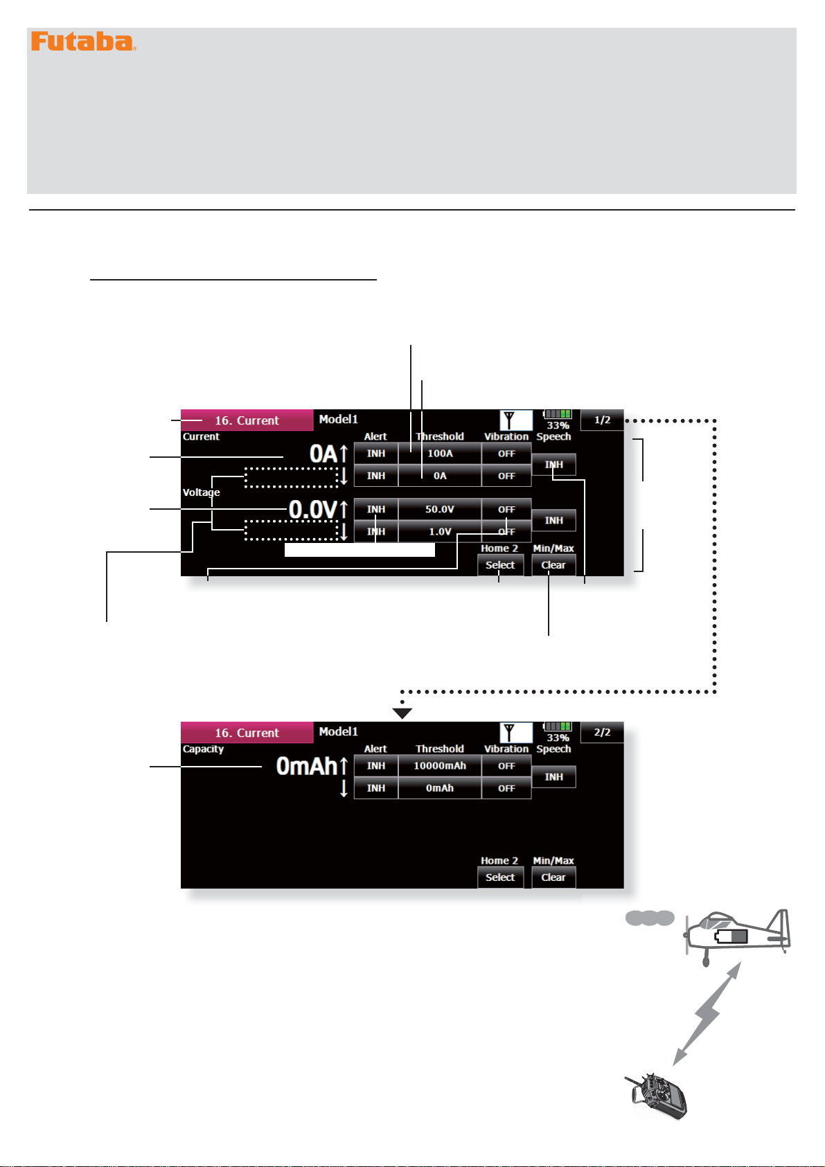
Current / Voltage / Capacity Display
The SBS-01C has the capability of measuring
current, voltage and capacity from drive battery at
the same time.
ŏ&DOOWKHIROORZLQJVHWWLQJVFUHHQE\SUHVVLQJWKH
>7HOHPHWU\@EXWWRQRIWKH/LQNDJH0HQX
ŏ5HWXUQWR
7HOHPHWU\
ŏ'ULYH
EDWWHU\
current
ŏ'ULYH
EDWWHU\
voltage
ŏ3UHVVWRVHWXSYLEUDWLRQDOHUWV
W\SHVRIYLEUDWLRQVHOHFWLRQVDUHSRVVLEOH
ŏ7KLVGLVSOD\LVWKHPD[LPXPDQG
minimum after starting reception until
the transmitter is turned off.
PLQPD[
PLQPD[
ŏ3UHVVWRVHWXSDQDOHUW
ŏ,IWKLVYDOXHLVH[FHHGHG
the alarm will operate
ŏ,ILWEHFRPHVORZHUWKDQWKLV
YDOXHWKHDODUPZLOORSHUDWH
ŏ6HOHFWVWKHVHQVRU
displayed on home 2
screen.
ŏ'LVSOD\VWKHPD[LPXP
and minimum value
ranges. [Clear] to reset.
*Current sensor SBS-01C is required.
ŏ&KDQJHRI
a numerical
value
ŏ,1+ń$&76RXQGVD
voice alert in addition
to the alarm sound
when the alarm is
activated.
ŏ'ULYH
EDWWHU\
capacity
*Refer to the manual of SBS-01C for the details of wiring.
Page 2
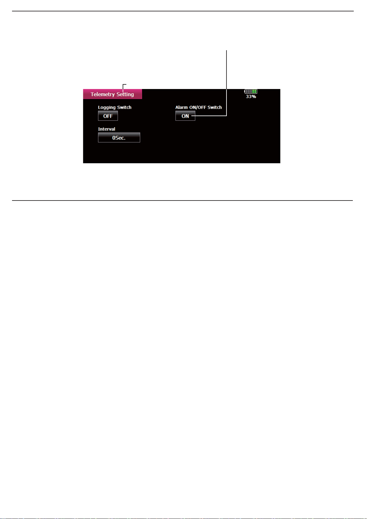
2. Addition of telemetry ON/OFF switch function
Turns ON/OFF the telemetry alarm.
It changed from [Telemetry Log] to [Telemetry Setting].
ŏ7RXFKWKH>7HOHPHWU\6HWWLQJ@EXWWRQLQ WKH /LQNDJH
0HQXWRFDOOWKHVHWXSVFUHHQVKRZQEHORZ
ŏ5HWXUQWR/LQNDJH0HQX
3. It corresponded to the following sensor.
Refer to the sensor instruction manual for more information.
ٹ ŦƄƖƗƏƈŃŷůœ
ŏ7RVZLWFKVHOHFWVFUHHQ
7XUQV212))WKHWHOHPHWU\DODUP
$OOWHOHPHWU\DODUPVVWRS
Page 3
T18MZ SOFTWARE UPDATE CHANGES
1M23N26419
This software updates or alters the functions and features noted below. The instructions and information that follow are meant as a supplement to the original instruction
manual that accompanied the T18MZ transmitter. Please refer to the original instr uction manual where applicable, but replace the steps indicated below with these
instructions. Please note that the software update will be finalized the first time that the T18MZ is powered up, after the software has been applied. As such, it may require a
few moments before the Start screen appears. Please check to ensure that the update has been installed.
1) Select the System Menu.
2) Touch the [Information] button.
3) Confirm that the information in the display indicates the Editor and Encoder version numbers as noted above.
(Editor Version: 2.5 Encoder version: 2.2)
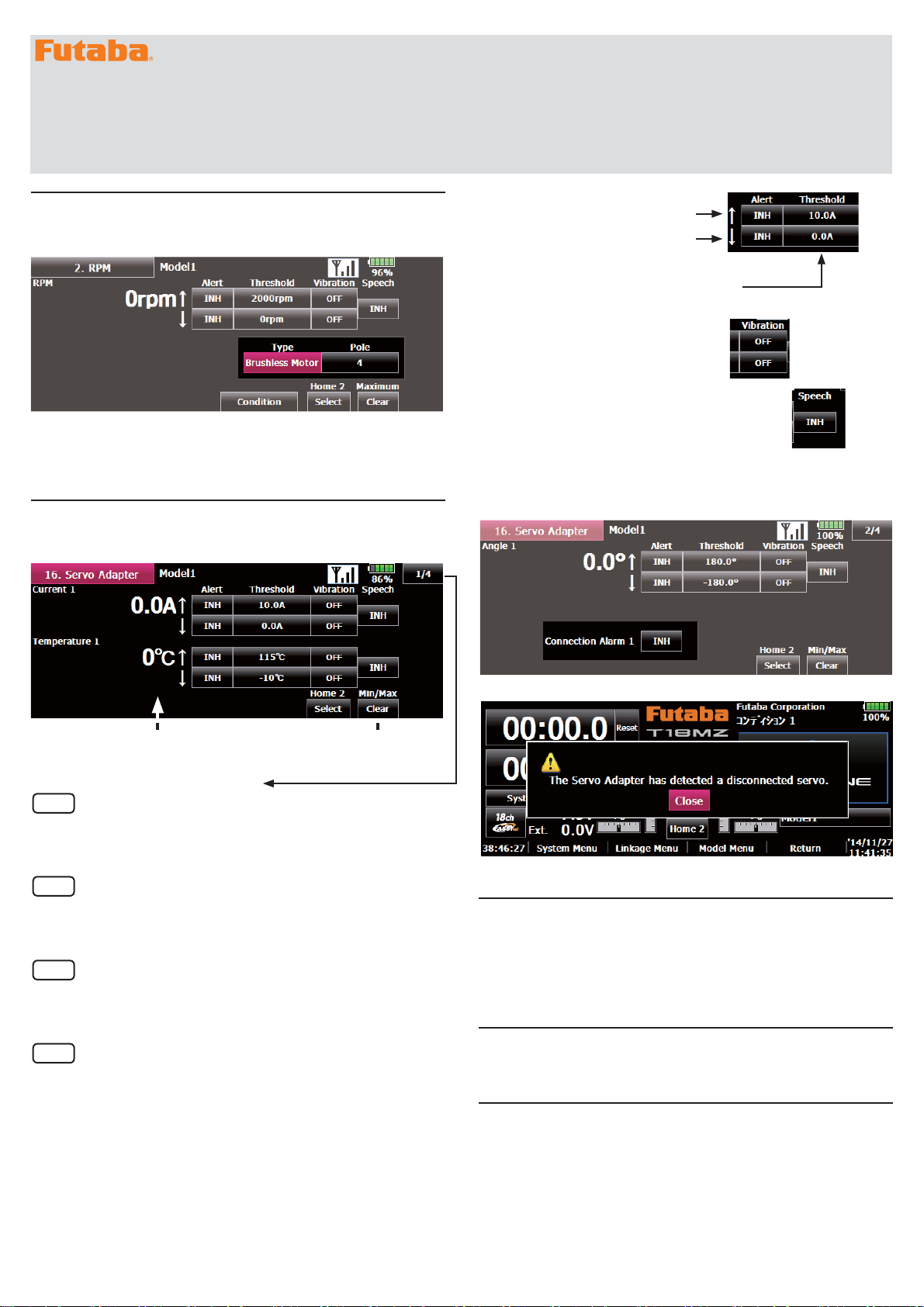
1. SBS-01RB Brushless motor RPM sensor function
The T18MZ has been made compatible with the SBS-01RB brushless
motor RPM sensor.
■ "Type" → "Brushless Motor"
■ "Pole" → Each aircraft using a brushless motor has a different number of
poles. The number of poles of the motor used must be checked against
the motor instruction manual and entered at the "Pole".
2. SBS-01S S.BUS2 servo sensor function
The T18MZ has been made compatible with the SBS-01S S.BUS2 servo
sensor.
Indicates that the alarm will start when
the current rises above the set value.
Indicates that the alarm will start when
the current falls below the set value.
③ The numerical value is input to "Threshold".
④ Press to setup vibration alerts. 4 types of
vibration selections are possible.
⑤ Press to setup "speech". A voice alarm is given in
addition to the alarm sound when the alarm was
activated.
⑥ Activate the servo connection alert function by touching the [Connection
Alarm] [INH] button.
[INH] ⇒ [ON/OFF].
Telemetry data / Min Max data Min Max data is reset.
When 1/4 is pushed, it's to the next page.
page
1/4
◆ Current 1 ⇒ Current alert setting of servo 1
◆ Temperature 1 ⇒ Temperature alert setting of servo 1
page
2/4
◆ Angle 1 ⇒ Angle alert setting of servo 1
◆ Connection Alarm 1 ⇒ Connection alert setting of servo 1
page
3/4
◆ Current 2 ⇒ Current alert setting of servo 2
◆ Temperature 2 ⇒ Temperature alert setting of servo 2
page
4/4
◆ Angle 2 ⇒ Angle alert setting of servo 2
◆ Connection Alarm 2 ⇒ Connection alert setting of servo 2
【Setting method】
① At the linkage menu Telemetry screen, select "Servo Adaptor".
② Activate the alert function by touching the [Alert] [INH] button.
[INH] ⇒ [ON/OFF].
This screen appears and an alarm sounds to indicate a servo connection error.
3. It corresponded to the following sensor.
Refer to the sensor instruction manual for more information.
ٹ ŮƒƑƗƕƒƑƌƎŃŮƒƖƐƌƎ
ٹ ŵƒƅƅƈŃŵŲŻŻż
ٹ ŭƈƗŃŦƄƗŃŹŔœ
ٹųƒƚƈƕťƒƛ
4. Dual receiver function (Addition of instructions)
A telemetry function cannot be used for the 2nd receiver. The voltage and
Ext voltage of a 2nd receiver cannot be monitored with a transmitter.
5. Area Code is EUROPE only FASST and S-FHSS
applied to EN300 328 V.1.8.1
FASST MULTI CH mode, 7CH mode and S-FHSS apply to EN300 328
V.1.8.1adaptive system. (V.1.8.1 is the latest version of European regulation
for 2.4GHz radio equipment which can output RF power less than 100mW.)
Page 4

T18MZ SOFTWARE UPDATE CHANGES
1M23N26419
This software updates or alters the functions and features noted below. The instructions and information that follow are meant as a supplement to the original instruction
manual that accompanied the T18MZ transmitter. Please refer to the original instr uction manual where applicable, but replace the steps indicated below with these
instructions. Please note that the software update will be finalized the first time that the T18MZ is powered up, after the software has been applied. As such, it may require a
few moments before the Start screen appears. Please check to ensure that the update has been installed.
1) Select the System Menu.
2) Touch the [Information] button.
3) Confirm that the information in the display indicates the Editor and Encoder version numbers as noted above.
1. Variometer melody ON/OFF switch function
A function that can turn the altimeter and GPS variometer melody (function
that signifies that the aircraft is rising or diving by means of a melody) on
and off has been added.
【Setting method】
① At the linkage menu Telemetry screen, select Altimeter (Altitude) or
Altimeter (Vario).
② Set Melody to ON and press NULL and select the desired switch.
③ Set the switch ON/OFF position.
■ Only toggle switch can be selected. The alternate function (function that
repeats ON → OFF → ON →・・・each time the switch is operated)
cannot be used.
2. Extra voltage alert specifications change
The receiver and voltmeter external voltage input terminal (ExtraVoltage)
was specified to stop the alarm when the external input voltage was 0V.
However, this has been changed so that the alarm is generated even when
the external input voltage is 0V only when the alarm voltage was set to 0V.
3. Telemetry data log function
Telemetry data has been adapted to the log function which is recorded at
the SD card.
【Setting method】
① Open the linkage menu Telemetry Log screen.
(Editor Version: 2.4 Encoder version: 2.0)
■ Extension FLI: Slot allocation information file
■ Extension FLD: Log data file
*When copying or moving a log file, always select both the .FLI file and
.FLD file.
Log files can be converted to CSV format by using the telemetry log
converter available at the Futaba website.
■ Notes
Altimeter altitude data and GPS distance and altitude data output with
◇
the point that time logging started as the reference (0m). When the
transmitter preset position and the log start position are different, the
transmitter display and the log data display will also be different. The
altitude and distance from the take-off position can be recorded by
starting logging immediately after take-off.
The transmitter gear ratio or number of fins setting is not reflected in
◇
the speedometer log data (speed). Multiply the gear ratio or number of
fins by the speed data.
When the SD card becomes full, recording stops and does not resume
◇
even if logging is restarted.
4. Altimeter display units change
The altimeter and GPS display units when the display units system is set to
yards and pounds has been changed.
■ Vario fpm (ft / min)
■ Pressure inHg (inch of mercury)
5.Addition of S.BUS servo setting function
A servo type setting function was added to S.BUS compatible servos other
than the S3171SB, S9071SB, S9072SB, S9074SB, and S9075SB.
■ Normal: Normal operation mode
■ Retract: Landing gear retract mode. When a load is applied to the
servo for 30 seconds without any channel operation performed from the
transmitter, the current consumption is suppressed by widening the dead
band to 40°. When channel operation is performed from the transmitter,
or the servo is moved outside the expanded dead band by an outside
force, dead band expansion is reset and returns to the original operation.
■ O.L.P. : This is the Over Load Protection mode. When a servo horn has
been locked for more than 5 seconds by a load, the servo output turns off
to protect the servo.
② Log recording can be started and stopped by operating a switch. The
Log Start/Stop switch is selected.
③ The log output interval can be set.
* The data to be recorded is updated at the time set by Linkage
Menu → System Type screen D/L Interval. For example, when the log
output interval is 1 second and the D/L interval is 2 seconds the same
data is overlapped and recorded twice.
【Operation method】
① Insert the SD card into the card slot.
② Set the switch set by Log Start/Stop Switch to ON. A beep sounds and a
log file is created and recording of the telemetry data begins.
AbsolutelyneverremovetheSDcardwhilelogdataisbeing
recorded.
③ Set the switch set by Log Start/Stop Switch to OFF. A beeping sound is
generated and recording of the telemetry data stops.
④ Turn off the transmitter power and remove the SD card.
■ Log file
A log file is created in the SD card LOG folder. Two files with the same
filename, but a different extension are created. (Example: 00001234.FLI,
00001234.FLD)
■ The normal mode and retract mode are applicable only to the S3171SB,
S9071SB, S9072SB, S9074SB, and S9075SB.
6.Robbe current sensor (F1678) function
The T18MZ has been made compatible with the Robbe current sensor
(F1678). The current, voltage, and battery capacity can be displayed. Refer
to the Robbe current sensor instruction manual for more information.
Page 5

1M23N26412
T18MZ SOFTWARE UPDATE CHANGES
(Editor Version: 2.1,2.2 and 2.3 Encoder version: 2.0)
This software updates or alters the functions and features noted below. The instructions and information that follow are meant as a supplement to the original instruction
manual that accompanied the T18MZ transmitter. Please refer to the original instruction manual where applicable, but replace the steps indicated below with these
instructions. Please note that the software update will be finalized the first time that the T18MZ is powered up, after the software has been applied. As such, it may require a
few moments before the Start screen appears.
Please check to ensure that the update has been installed.
1) Select the System Menu.
2) Touch the [Information] button.
3) Confirm that the information in the display indicates the Editor and Encoder version numbers as noted above.
Voltage display function
This function allows some voltage sensor units to be compatible with
Futaba's voltage sensor unit (SBS-01V).
【Setting method】
① Register the SBS-01V at the transmitter from the [Sensor] setting screen
in the Linkage Menu.
② The [Telemetry] screen in the Linkage Menu opens. The voltage
information is displayed.
9ROWDJH
■ [Alert]: If it turns OFF (ON) from INH, it will warn at the time of voltage
drops.
■ [Threshold]: The voltage which starts warning is inputted.
■ [Vibration]: If Type 1-4 is used from OFF, it will warn by each vibration.
■ [Speech]: INH → ACT ; a voice alarm is given in addition to the alarm
sound when the alarm was activated.
The voice of T18MZ
The voice of T18MZ changed from the man to a woman.
*
The change part of V2.3 is only this.
*
The change part of V2.3 is only this.
Home 2 screen telemetry display function
The Home 2 screen telemetry display function has been refined to display
more information. In addition to the current measured value, the display
also indicates the minimum and maximum values.
【Setting method】
① Touch the [Home 2] button in the Home screen to open the [Home 2]
screen.
② Select the desired sensor unit, and open the details display screen.
③ Touch the [Select] button on the [Home 2] screen. The Home 2 setting
screen appears.
Audible telemetry information
In addition to the on-screen telemetry data information, the T18MZ now has
the ability to audibly indicate the aircraft status.
■ The voice is in English.
■ The audible indicator is capable of noting the data from any (or all) of the
three sensors selected.
■ When using the voice read function set the [Timer and PIT and THR]
setting of the Home 2 screen to the [OFF] mode.
■ It is possible to adjust how often the data is conveyed to the modeler.
The frequency ranges from 0-30 seconds. If set at 0, updates will occur
continuously. If set to 30, updates will occur every 30 seconds.
■ The T18MZ offers the ability to adjust the volume of the audible telemetry
data. The volume for the telemetry data is combined with the Error/
Warning volume. To access this adjustment: [System Menu] -->[Sound
Volume] -->Error/Warning.
■ It is also possible to turn the audible information on/off by the use of an
arbitrary switch and/or switch position.
■ When only one kind of data is set to read ON, the data is repeatedly
read in the following order:
[Sensor Type, Data, Units] [Data] [Data] [Data] [Data]
(Example) Reading of receiver voltage
"Battery eight point one volt, eight point one, eight point one, eight point
one, eight point one, Battery..." is repeated. If you have activated the
audible indicators for multiple sensors, the T18MZ will cycle through the
indicators at the selected timing intervals accordingly.
■ When the voice read function is turned on for telemetry data with alarm
set when an alarm is activated; a voice alarm is given in addition to the
alarm sound when the alarm was activated.
["Warning"] [Sensor Type, Data, Units]
【Setting method】
① In the Linkage menu, select the telemetry screen to make adjustments to
the sensors. Touch the button associated with the sensor for which you
would like to adjust.
② If both the alarm (alert) and the speech (audible information) indications
are active, and the alarm threshold is exceeded, the T18MZ will sound a
warning accordingly.
■ Alternatively, the detail display screen may be accessed as follows:
[Linkage Menu] → [Telemetry] → selected sensor → Home 2 [Select]
④ It is possible to display up to three types of telemetry data on the Home
2 screen.
■ [Display]: The value indicated (on/off) determines whether or not the
sensor data will be displayed in the Home 2 screen.
■ [Slot]: Sets the slot number of the sensor unit to be displayed.
■ [Sensor type]: Displays the selected sensor type.
■ [Value Type]: Indicates the data to be displayed from among the
measured data of each sensor unit.
■ [Timer and PIT and THR]: When set to [ON], displays the timer (when the
model type is helicopter, pitch/throttle position) on the Home 2 screen.
When set to [OFF] displays the telemetry data maximum and minimum
values and the voice button on the Home 2 screen.
● Home 2 screen when [OFF]
③ Touch the [Select] button of [Home 2]. The Home 2 setting screen
appears. Set [Timer and PIT and THR] to [OFF]
④ Select the telemetry data that is to be read by voice.
⑤ As mentioned previously, it is possible to adjust the time, or interval,
between the audible updates from the sensor(s). To do so, press the
speech Interval button then use the rate adjustment buttons to select the
desired interval. The interval ranges from 0 (continual updates) to 30
(information noted every 30 seconds). Press [Close] when done.
-1 -
Page 6

⑥ Press the [Home 2].
Telemetry display units setting
The telemetry display units can now be set to metric system or Imperial
system.
【Setting method】
① Open the telemetry display units setting screen by touching [Unit
System] in the System Menu.
② Select [Metric] or [Yard-pound].
⑦ Speech ON/OFF can be switched by switch. When the [Switch] button
is touched the switch setting screen opens. When the set switch is
operated voice reading starts. When multiple switches were set to ON
simultaneously, setting of the top line has priority.
Variometer melody function
When using a variometer, the T18MZ offers the option of incorporating a
tonal indication of the aircraft's rate of ascent or descent.
■ To ensure that the pilot is aware as to the model's status, the T18MZ
incorporates a different melody for ascent and descent. Additionally,
depending upon the rate of climb or descent, the tones vary to indicate
whether or not the airplane is climbing or descending at a rapid rate.
■ The melody function and the voice read function can be used simultaneously.
When the voice read function was turned on data is read as follows:
Climbing: [Climb, climb speed, m/s]
Sinking: [Sink, sink speed, m/s]
【Setting method】
① Open the altimeter details setting screen from the [Telemetry] screen in
the Linkage Menu.
② Set the [Melody] button to [ON].
Timer function
This update to the T18MZ incorporates vibration alerts that notify the
modeler when the programmed time limits have been reached.
This function also allows the timers to be controlled via the home screen.
【Setting method】
① Press the 1/2 button to access the second page of the [Timer] menu.
② The vibration pattern when the timer reaches the set time can be
selected by touching the [Vibration] button. When set to [OFF], the vibe
function is not performed.
③ Operation when the timer button on the home screen was touched can
be changed by touching the [Button Mode] button.
[Setup screen]: Timer is controlled via the setup screen. [start/stop]: Timer
start/stop
■ A timer reset button has been added to the home screen.
GPS display function
This function allows some GPS units to be compatible with Futaba's GPS
unit (SBS-01G).
【Setting method】
① Register the GPS unit at the transmitter from the [Sensor] setting screen
in the Linkage Menu.
② The [Telemetry] screen in the Linkage Menu opens. The GPS unit
information is displayed.
■ GPS (distance) and GPS (speed) setting screen
This screen displays the distance, speed, and position. When the [Preset]
button of [Position] is touched, the distance measurement reference position
is initialized.
*Editor Version: 2.2 [Distance]
is displayed.
The [Distance] button [Surface]
or [Slant] can be chosen.
The change part of V2.2 is only this.
*
*Editor Version: 2.2
It is the accuracy
display of GPS.
Please use it,
pushing preset after
displaying three.
Slant
Altitude
Surface
■ GPS (altitude) and GPS (variometer) setting screen
This screen displays the altitude, variometer, and air pressure. When [Preset]
of [Reference Point (Altitude)] is touched, the altitude measurement reference
altitude is initialized.
Touch panel lock function
To prevent any unwanted or undesired transmitter input, this update
incorporates touch panel locking functions.
The Start Up Lock function, if active, will automatically lock when the power
is turned on.
The Automatic Lock function will lock the transmitter when the backlight
timing has elapsed.
【Setting method】
① Open the screen setting screen by touching the [Display] button in the
System Menu.
② To activate the start up lock function, press the INH button below Start
-up lock.
[ON]:Start-up lock on
[INH]:Start-up lock inhibited
③ To activate the automatic lock function, press the INH button below the
Automatic lock.
[ON]:Automatic lock on
[INH]:Automatic lock inhibited
S.BUS servo setting screen
It is now possible to check servo operation at the S.BUS servo setting
screen.
【Setting method】
① Open the S.BUS servo setting screen by touching the [S.BUS Servo]
button in the System Menu.
- 2 -
Page 7

② Connect an S.BUS servo to the S.BUS setting connector on the back
of the transmitter. Connect the battery to the sensor unit using a 2-way
cord, etc.
*Please note, this function is not applicable to the S9070SB servo.
③ Read the servo data by touching the [Read] button.
④ An operation check signal is output to the servo from the transmitter.
When the transmitter switch or stick that controls the channel allocated to
the S.BUS servo is operated, the servo will move accordingly.
Data reset screen
This update allows the user to separately reset the information for user
menus and telemetry data, if desired. For example, it is now possible
to reset the telemetry information without impacting the other model
programming.
【Setting method】
① Open the data reset screen by touching the [Data Reset] button in the
Linkage Menu.
② To reset the user menu setting, touch the [User Menu] button. To reset
the telemetry settings, touch the [Telemetry] button.
Camera function shutter switch
This update allows the user to assign a switch/position to control the
camera function of the T18MZ.
【Setting method】
① Open the camera screen by touching the [Camera] button in the System
Menu.
② To determine the switch to be used for the camera shutter, press the
switch select button located below the shutter button. Next, determine the
switch and the activation direction.
Nextexplanationisrequiredwhenusing
twoormorethesamekindofsensors.
【Example1 Altitudesensor × 1,Temperaturesensor × 1】
Asetupisunnecessary.
TwosensorsarepackedbyHUBanditconnectswithS.BUS2
ofareceiver.
【Example2 Altitudesensor × 1,Temperaturesensor × 2】
Onealtitudesensor andonetemperaturesensor,itis
unnecessarytosetup.
Sensorregistrationis neededaboutthe2ndtemperature
sensors.
Assignable slot
<
The
Sensor
TEMP (SBS-01T) 1 slot 1 〜 31
RPM
(SBS01RM,SBS-
01RO)
Voltage (SBS-01V) 2 slots
Altitude (SBS-01A) 3 slots
GPS (SBS-01G) 8 slots 8,16,24
TEMP125-F1713 1 slot 1 〜 31
VARIO-F1712 2 slots
VARIO-F1672 2 slots
GPS-F1675 8 slots 8,16,24
required
number
of slots
1 slot 1 〜 31
*Altitude sensors, GPS sensors and other
data sensor units may use multiple slots.
*The sensor which uses two or more slots
>
has restriction in a start slot.
The number which can be
used as a start slot
1,2,3,4,5,6,
8,9,10,11,12,13,14,
16,17,18,19,20,21,22,
24,25,26,27,28,29,30
1,2,3,4,5,
8,9,10,11,12,13,
16,17,18,19,20,21,
24,25,26,27,28,29
1,2,3,4,5,6,
8,9,10,11,12,13,14,
16,17,18,19,20,21,22,
24,25,26,27,28,29,30
1,2,3,4,5,6,
8,9,10,11,12,13,14,
16,17,18,19,20,21,22,
24,25,26,27,28,29,30
Selling area
Global
Europe
Maximum engine revolution display by each condition
It is now possible to display maximum engine revolutions by each condition.
【Setting method】
① Touch the [Condition] button on the RPM display.
② The screen that appears next denotes the maximum RPM achieved for
each of the flight conditions programmed into the transmitter.
Sensor unit ID setting
There are two methodologies that may be used to register the
identification of the sensors used with the T18MZ. This may be done
manually within the transmitter's program. Alternatively, registration of the
sensor may be accomplished through the sensor unit registration function
which follows.
【Setting method】
① Open the sensor unit setting screen by touching the [Sensor] button
in the Linkage Menu. The name and ID of the sensor assigned to each
slot is displayed.
② Touch the [ID] button of the desired slot.
③ To manually enter, or change the identification of the desired sensor(s),
input the identification using the touchpad. When completed, press OK.
Sensor unit registration
The sensor unit of each transmitter slot is registered and the slot number
of each sensor unit is changed automatically.
【Setting method】
- 3 -
Page 8

① Insert a two-way cord, such as a dual servo extension (FUTM4135),
into the S.BUS setting connection in the rear of the T18MZ. Connect a
battery to one port of the two-way cord and then insert the sensor to be
registered into the other.
② Open the sensor unit setting screen by touching the [Sensor] button in
the Linkage Menu.
③ Touch the 1/2 to enter the second page of the sensor screen. Then,
touch the [Register] button.
④ If registration is successful, the following screen will appear. Close the
message by touching the [Close] button.
⑤ If registration failed, the following message is displayed:
[There are not enough available slots]
Some sensors require multiple continuos slots for their operation. For
example, slots 3-6. If continuous slots are not available, these sensors will
not be registered accordingly.
If there are unused slots, but they are not continous, please use the sensor
unit reallocation feature, which follows, to change the slots of the existing
sensors to accommodate the sensors which require continuous slots.
-Altimeter: 3 slots required
-GPS: 8 slots required
[The connected sensor is not ready]
No response from sensor unit. Check the connections.
Sensor unit setting reread
This function rereads the slot number setting of the connected sensor
units. This is a convenient way to allow another T18MZ user to pilot your
aircraft.
【Setting method】
① Connect all registered units to the S.BUS connection in the rear of the
transmitter. Additionally, it is necessary to connect a battery to these
sensor units via a two-way cord such as the dual aileron extension
mentioned above.
② Open the sensor unit setting screen by touching the [Sensor] button in
the Linkage Menu.
③ Touch the 1/2 to enter the second page of the setting screen. Then,
touch the [Reread] button.
④ If reread was successful, a screen like the following is displayed:
Sensor unit reallocation
used.
This function is used to reallocate slots to ensure that all sensors are
registered and operate as desired.
As noted above, some sensors require adjoining, or continuous, slots in
order to register properly. Examples of such sensors include but are not
limited to, altimeters and GPS units.
【Setting method】
① To properly reallocate the slots, it is necessary to connect all registered
units to the S.BUS connection in the rear of the transmitter. Additionally,
it is necessary to connect a battery to these sensor units via a two-way
cord such as the dual aileron extension mentioned above.
② Open the sensor unit setting screen by touching the [Sensor] button in
the Linkage Menu.
③ Touch the 1/2 to enter the second page of the setting screen. Then,
touch the [Relocate] button.
④ If reallocation was successful, a screen like the following will appear:
*Normally this function does not have to be
Sensor name function
As the name suggests, this feature allows you to rename the sensors
accordingly. This is very useful when a model has multiple sensors of the
same variety (e.g., temperature).
【Setting method】
① Touch the [Sensor Name] button in the Linkage Menu to open the
setting screen. A list of sensor units is displayed.
■ Please note, only sensor units assigned a slot are displayed.
② Select the type of sensor unit for which the name is to be changed. A
name change screen appears. When multiple sensor units of the same
type are registered, the [Slot] button is displayed. Select the slot to
which the sensor unit whose name is to be changed.
③ Touch the [Rename] button. A character input screen appears. Input
the new name. (Up to 16 characters)
④ If so desired, the sensor name can be returned to the default by pressing
the [Reset] button.
■ If all the registered sensors are not connected, the following message is
displayed and reallocation is not performed. Set slots allocated to unused
sensors to [Inhibit] on the sensor unit setting screen.
1080 Yabutsuka, Chosei-mura, Chosei-gun, Chiba-ken, 299-4395, Japan Phone: +81 475 32 6982, Facsimile: +81 475 32 6983
FUTABA CORPORATION
- 4 -
©FUTABA CORPORATION 2016, 3 (2)
 Loading...