

Page 1
3PK
3-CHANNEL RADIO CONTROL SYSTEM INSTRUCTION MANUAL
Futaba© Digital Proportional R/C System
Technical updates and additional programming examples available at:
http://www.futaba-rc.com/faq/faq-3pk.html
FUTZ8533 for FUTJ32**/33** V1.0
Entire Contents © Copyright 2002
3PK with Optional Accessory Offset Adapter Installed
Page 2
2
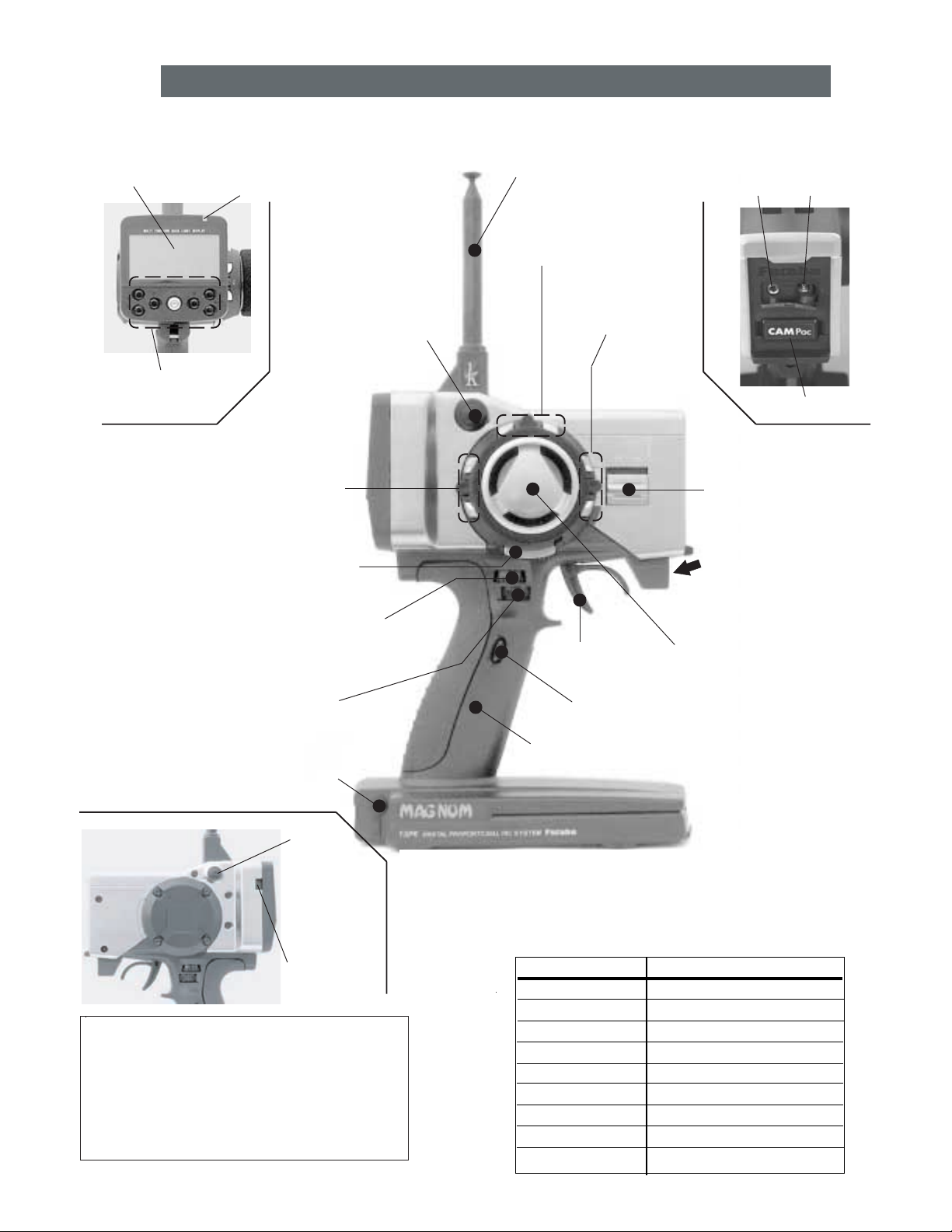
Transmitter Controls
DEFAULT ASSIGNMENT TABLE
The factory default functions activated by the switches and knobs are
shown below. Default assignments may be changed using the
FUNC-DIAL
and
FUNC-SW
programming (See pp. 34-35.) Features assigned to DL1, 2, 3, and
DT1, 2, 3 are displayed at all times on right side of LCD screen.
CONTROL DEFAULT
DT1 Steering trim
DT2 Throttle trim
DT3 NONE
DL1 Steering dual rate
DL2 ATL
DL3 Channel 3
PS1 NONE
PS2 NONE
PS3 NONE
*The switches, knobs and trimmers may all be reassigned. (see pp. 34-35)
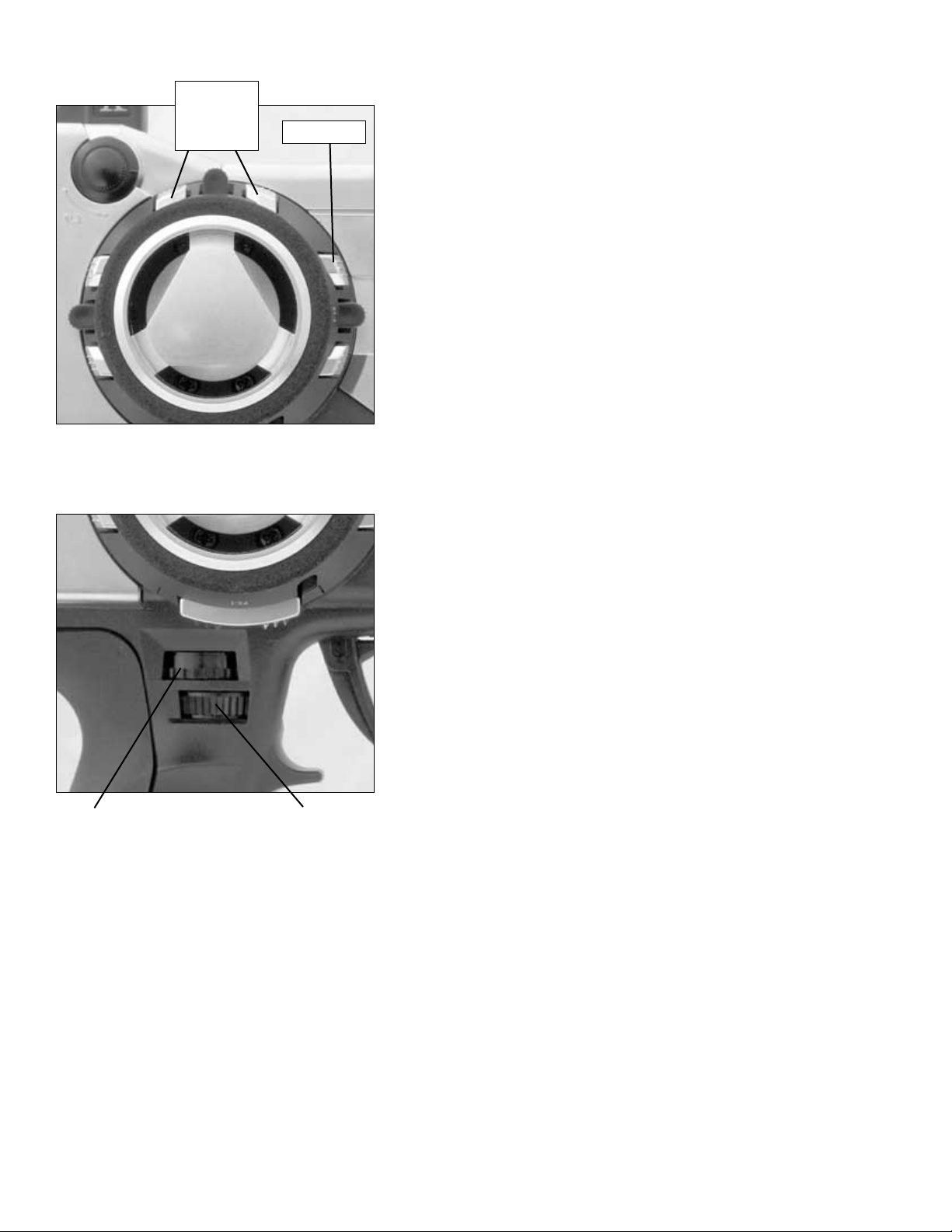
LCD screen
Pilot lamp
Edit buttons
Digital trim 2
(DT2) (default throttle trim)
(See page 9 for operating instructions.)
Push switch 1 (PS1)
Digital Dial 1 (DL1)
(default steering dual rate)
(See page 9 for the operating instructions.)
Digital Dial 2 (DL2)
(default ATL)
(See page 9 for the operating instructions.)
(See page 12 for
instructions to
change colors.)
Digital Dial 3 (DL3)
(default CH3 knob)
Antenna
Digital trim 1 (DT1)
(default steering trim)
(See page 9
for operating instructions.)
Digital trim 3 (DT3)
(See page 9
for operating instructions.)
Throttle
trigger
Push switch 2 (PS2)
DSC
Port
CAMPac
Power
switch
Mechanical ATL
adjusting screw
(See page 50 for the
adjustment instructions.)
Steering wheel
Charge
Port
Sound port
Use a commercial earphone
with a 3.5mm diameter plug.
Push
switch
3
(PS3)
Display
switch
Precautions when turning the power
switch on and off.
When the data is changed using the edit keys or
trim levers, wait at least two seconds before
turning off the power. If the power is turned off
within two seconds after the data was changed,
the new data will not be written to memory.
Grip Handle
Page 3

INTRODUCTION
•
Transmitter Controls and Defaults.................................2
•
Owner’s Manual and Additional Technical Help ..........4
•
Support and Service .......................................................4
•
Contents and Technical Specifications ..........................5
•
Optional Accessories......................................................5
•
A Quick Introduction to the 3PK System......................6
•
Getting to Know the Transmitter...................................8
•
Display Switch .......................................................8
•
Digital Trim Operation...........................................9
•
Digital Grip Dial Operation ...................................9
•
Installation....................................................................10
PROGRAMMING..........................................................11
•
Menu Selection Overview............................................11
•
Direct Selection Menu Overview.................................11
•
LV1 Functions ...............................................................12
•
Level Selection LEVEL-SEL ...................................12
•
System Settings SYSTEM.......................................13
•
Backlighting LHT-MODE ............................13
•
Backlighting time LHT-TIME.......................13
•
LCD contrast CONTRAST ............................13
•
Buzzer tone BUZ-TONE ...............................13
•
LED pilot lamp LED-MODE ........................13
•
Home screen display DISPL-SEL ................13
•
Model Selection MDL-SEL ....................................14
•
Model Name MDL-NAME ......................................15
•
User Name (set within MDL-NAME) ..........15
•
Modulation MOD-MODE ........................................16
•
Failsafe and Battery Failsafe FAIL-SAFE ...............17
•
Servo Reversing CH-REV.......................................18
•
End Point Adjustment CH-EPA .............................18
•
Exponential ST-EXP, TH-EXP ..................................20
•
Sub-Trim SUB-TRIM..............................................22
•
LV2 Functions ...............................................................23
•
Speed ST-SPEED, TH-SPEED ...................................23
•
ABS ABS...............................................................24
•
Throttle Acceleration TH-ACCEL ...........................26
•
Idle-up IDLE-UP.....................................................27
•
Auto-Start/Engine Cut AT-START ..........................28
•
Timer TIMER .........................................................30
•
Lap List LAP-LIST..................................................31
•
Model Reset MDL-RES ..........................................32
•
Model Copy MDL-COPY ........................................33
•
Function FUNC-SW, FUNC-DIAL..............................34
•
Direct Selection Menu Options DIRC-CALL ..........36
•
LV3 Functions ...............................................................37
•
Throttle Electronic ATL TH-ATL............................37
•
Steering Dual Rates ST-D/R .................................38
•
Servo Display SERVO............................................39
•
Channel 3 Position CH3-POSI ...............................40
•
Programmable Mixes PRG-MIX1, PRG-MIX2.........40
•
Brake Mix BRAKE-MIX..........................................42
•
Boat Mode BOAT-MODE ........................................43
•
MC Setup MC-SETUP ............................................44
•
Adjuster ADJUSTER ...............................................45
APPENDICES ................................................................46
•
Appendix I - Precautions and Warnings ......................46
•
Application, Export and Reconstruction..............46
•
Liability and Warranty .........................................46
•
Battery Recycling.................................................46
•
Meaning of Special Markings..............................47
•
Safety Precautions
(DO NOT operate without reading) ....................48
•
Mandatory Procedures for Using
HRS Receivers.....................................................48
•
Caring for your NiCd Batteries............................49
•
Appendix II - Adjustments, Modifications
and Replacements
•
Mechanical ATL/Wheel Tension Adjustment......50
•
Changing Wheel Position and Modifying for Left
Hand Use .....................................................................51
•
Appendix III - Error Displays......................................54
•
GLOSSARY/INDEX ...................................................56
•
Quick Setup for Nitro Engines ....................................67
•
Layout Reminder Guide...............................................67
•
Quick Start Guide .........................................Back Cover
3
TABLE OF CONTENTS
Note that in the text of this manual any time we are using a feature’s specialized name or abbreviation as seen on the screen
of the 3PK, that name, feature, or abbreviation will be exactly as seen on the radio’s screen, including capitalization, and
shown in a DIFFERENT TYPE STYLE for clarity.
Page 4

4
INTRODUCTION
Thank you for purchasing a Futaba
®
digital proportional R/C system. In order for you to make the best use of your system
and to use it safely, please read this manual carefully. If you have any difficulties while using your system, please consult
the manual, our online Frequently Asked Questions (on the web pages referenced below), your hobby dealer, or the Futaba
Service Center.
Owner’s Manual and Additional Technical Help
This manual has been carefully written to be as helpful to you, the new owner, as possible. There are many pages of setup
procedures and examples. However, it need not be your sole resource of setup guidelines. For example, the back cover
includes a quick-start set of instructions and the Frequently Asked Questions web page referenced below includes this type
of step-by-step setup instructions for a variety of other model types.
Due to potential unforeseen changes in production procedures, the information contained in this manual is subject to change
without notice. No part of this manual may be reproduced in any form, at any time, without prior permission.
Support and Service: It is recommended to have your Futaba equipment serviced annually during your hobby’s “off
season” to ensure safe operation.
IN NORTH AMERICA
Please feel free to contact the Futaba Service Center for assistance in operation, use and programming. Please be sure to
regularly visit the Frequently Asked Questions web site referenced below. This page includes extensive programming, use,
set up and safety information on your radio system and is updated regularly. Any technical updates and US manual corrections
will be available on this web page. If you do not find the answers to your questions there, please see the end of our F.A.Q.
area for information on contacting us via email for the most rapid and convenient response.
Don’t have Internet access? Internet access is available at no charge at most public libraries, schools, and other public
resources. We find internet support to be a fabulous reference for many modelers as items can be printed and saved for future
reference, and can be accessed at any hour of the day, night, weekend or holiday. If you do not wish to access the internet for
information, however, don’t worry. Our support teams are available Monday through Friday 8-5 Central time to assist you.
FOR SERVICE ONLY: FOR SUPPORT:
Futaba Service Center (PROGRAMMING AND USER QUESTIONS)
1610 Interstate Drive Please start here for answers to most questions:
Champaign IL 61822 www.futaba-rc.com\faq\faq-3pk.html
www.hobbyservices.com FACSIMILE: 217-398-7721
PHONE: 217-398-8970 option 4
HOW TO SEND FOR SERVICE:
www.hobbyservices.com\techsupport\service-form-futaba.pdf
www.hobbyservices.com\techsupport\service-form-futaba.html
OUTSIDE NORTH AMERICA
Please contact your Futaba importer in your region of the world to assist you with any questions, problems or service needs.
Please recognize that all information in this manual, and all support availability, is based upon the systems sold in North
America only. Products purchased elsewhere may vary. Always contact your region’s support center for assistance.
Page 5

5
•
Transmitter, including RF module* (PK) and NiCd
battery pack NT8F700B (FUTM1462)
•
Receiver (R113iP or R203HRF)
•
110V wall charger FBC19B (USA)
•
Frequency Flag/Number set
•
Wheel position offset adapter (APA)
Transmitter T3PK (Pistol, 3 channels)
Operating system: FM/PCM1024/HRS
Transmitting frequency: 27, 75 MHz bands*
Modulation: FM/PPM, HRS-FM or PCM1024, switchable
Power supply: 9.6V NT8F700B NiCd battery
Current drain: 250 mA or less
Receiver R113iP ( PCM Single conversion, 3 channels)
Receiving frequency: 27, 75 MHz bands *‡
Intermediate freq.: 455 kHz
Power requirement: 4.8V or 6.0V NiCd battery or
4.8V (4 cells) alkaline
Current drain: 18 mA
Size: 1.69" x 1.13" x 0.63" [42.7 x 28.7 x 16.0mm]
Weight: 0.74oz [21g]
Receiver R203HF (3 channels, HRS single conversion)
Receiving frequency: 27, 75 MHz bands *‡
Intermediate frequency: 455kHz
Power requirement: 6.0V only (shared with servos)
Current drain: 14mA
Size: 1" x 1-1/2" x 9/16" [25.6 x 37.7 x 14.3mm]
Weight: .6oz [17g]
Always use only: “HRS” mode on transmitter
6V Digital Servo, including throttle
6V NiCd battery
* Transmitter band may only be changed by changing the
module. Receiver band cannot be changed. Band cannot be
changed by simply changing crystals.
‡ Only 27, 75MHz bands are legal for R/C ground use
in the North America.
Other bands are sold and used in other countries only.
CONTENTS AND TECHNICAL SPECIFICATIONS
(Specifications and ratings are subject to change without notice.)
Your system includes the following components:
The following additional accessories are available from your dealer. Refer to a Futaba catalog for more information:
•
CAMPac Memory module — the optional DP-16K CAMPac increases your model storage capability (to 20 models
from 10) and allows you to transfer programs to another 3PK transmitter. Note that data may not be transferred to/from
any other model of transmitter (3PJ, etc).
CAUTION - Insertion of a CAMPac containing data of a different transmitter type (ex: 3PJ) will result in
a complete CAMPac data reset and loss of all data.
•
Transmitter battery pack — the NT8F700B (700mAh) transmitter NiCd battery pack may be easily exchanged with a
fresh one to provide enough capacity for extended sessions.
•
Y-harnesses, servo extensions, etc – Genuine Futaba extensions and y-harnesses, including a Heavy-Duty version with
heavier gauge wire, are available to aid in your larger model and other installations.
•
5-cell (6.0V) receiver battery packs. All Futaba equipment (except that which is specifically labeled otherwise) is
designed to work with 4.8V (NiCd 4 cells) or 6.0V (NiCd 5 cells or alkaline 4 cells). Using a 6.0V pack increases the
current flow to the servos, which accelerates their rate of response and their torque. However, because of this faster
current draw, a 5-cell battery pack of the same mAh rating will last approximately ¾ the time of a 4-cell pack.
CAUTION - NOTE that HRS receivers require 6.0 volts and will not operate with 4.8V 4-cell packs.
•
Gyros – a variety of genuine Futaba gyros are available for your specialized model needs.
•
FailSafe: the FS1 FailSafe may be used with standard PPM/FM receivers to return throttle to idle in case of a loss of signal,
similar to the FailSafe function of PCM/HRS receivers. NOTE that HRS receivers can not operate with the FS1.
•
Battery Holder (Transmitter): This battery holder is necessary when using the transmitter with dry cell batteries. For a
description of how to install the battery holder to the transmitter, see “NiCd Replacement” on page 54.
•
DSC cord – allows setup and testing without transmitting. Requires DSC compatible receiver and DSC cord. With transmitter
and receiver off, plug cord into transmitter and then into receiver battery slot. Turn on receiver power. All programming and
setup may be done in this matter without transmitting. See glossary for a list of DSC-compatible receivers.
Page 6

6
A QUICK INTRODUCTION TO THE 3PK SYSTEM
TRANSMITTER: 3PK
•
Large graphic liquid-crystal display panel with 7 buttons for quick, easy set up.
•
128x64 dot large graphic LCD/with adjustable backlighting and graph displays for exponential, etc.
•
Includes 3 levels of flexibility to simplify programming for new users while still providing the most flexible system in
the world to those who wish to use it.
•
LV1: (Learning the system; quick setups, a single menu with enough for most models, including):
•
MDL-NAME 10-character model name
•
USR-NAME 10-character user name
•
MOD-MODE FM/PCM/HRS selection to match each model’s receiver
•
EPA End point adjustment for all servos
•
SYSTEM Adjust back light, contrast, volume, and items displayed on home screen
•
LEVEL-SEL Level Selection: Change programming complexity.
•
MDL-SEL Model Selection: Choose from the 10 models in memory or in optional CAMPac
•
MDL-RES Model Reset: Erase model memory for this model only
•
MOD-MODE Modulation: Transmission mode (PPM/PCM/HRS)
•
FAILSAFE Failsafe and Battery Failsafe: Program receiver's response in case of lost signal.
•
CH-REV Servo Reversing
•
EXP Exponential: Set exponential for braking and steering, and pick from 3 curve types for forward throttle,
•
LV2: (“Let’s Race!” Exploring 2 menus, with all of LV1, plus racer-focused features, including):
•
ABS Simulates antilock brakes with fully adjustable pulsing effect
•
SPEED Adjustable throttle/steering servo response on input and release
•
ACCEL Throttle acceleration minimizes delay in nitro engine/braking response
•
LAP Record lap times, set training target times, display 99 recorded times
•
AT-START/ENGINE CUT Avoid wheel spins or shut boat engines off safely
•
Idle-up Increased throttle setting for easy starts
•
FUNC Assigns features to any of the 6 dials/trims and 3 switches
•
Direct selection menu options Customize the Direct Selection Menu
•
MDL-COPY Copy one model memory into another for experimenting and more
•
LV3: (For the expert driver, boat or complex modeler, adds specialized features, including):
•
PRG-MIX 1,2 Programmable mixes in a car radio for your own special effects!
•
BRAKE-MIX Set up independently adjustable front and rear brakes.
•
BOAT-MODE Includes tilt steering (outboard/rudder mixing), ability to disable brake function
•
ST-D/R Two steering dual rates
•
SERVO Displays servo position to ease setup, test mixes prior to installation.
•
TH-ATL Adjust the brake's total travel
•
CH-3 Adjust channel 3's midpoint
•
MC SETUP Setup ESCs with HRS receivers
•
ADJUSTER Re-calibrate the radio for perfect performance every time
•
Supports Futaba’s new High Response System (H.R.S. system) receivers, as well as FM and PCM1024.
•
H.R.S. provides response times approximately 1/3 of that of an equivalent FM system.
•
CAMPac offers unlimited data storage.
•
User-defined home screen data display and quick-access Direct Call menu for Level 2 and 3 users.
•
Full function assignability for dials, digital trims, switches.
•
Adjustable wheel height and angle for perfect fit, as well as left-handed support.
•
Display switch allows programming setup without transmission.
•
Permanent memory storage via EEPROM with no backup battery to service or have fail.
Page 7
7
MODULE: 75PK-FM
•
Module may be easily removed and a module on a different channel (or even band) reinserted to change the
transmission frequency or band.
•
Module transmits FM (PPM), HRS-FM (HRS) and PCM. No need for a second module.
•
Module is protected under the RF module cover on the top of the radio.
•
All transmission circuitry is included in the module, so no retuning is needed when changing channels or even bands.
•
Frequency band is changed by inserting a module on the proper band, including for international use.
•
In North America it is against FCC regulation to change the crystal within the transmitter module to a different
channel. All such transmitter crystal changes must be performed by a certified radio technician. Failure to properly
tune a system to its new channel may result in decreased range and may also result in interference to other types of
frequency users on adjoining channels.
•
The FSS synthesized module for the 9Z family of radios is NOT compatible with the 3PK.
•
DISP displays instead of RF when main power is on and module is not installed.
•
It is normal for the module to get slightly warm during use.
•
Non-Futaba brand modules are not FCC certified for use with this radio and therefore are against FCC regulation to use.
•
Do not use other modules in the 3PK or the PK module in other radios.
•
Do not operate transmitter with module in and power switch on, while antenna is collapsed. Always extend antenna
if transmitting.
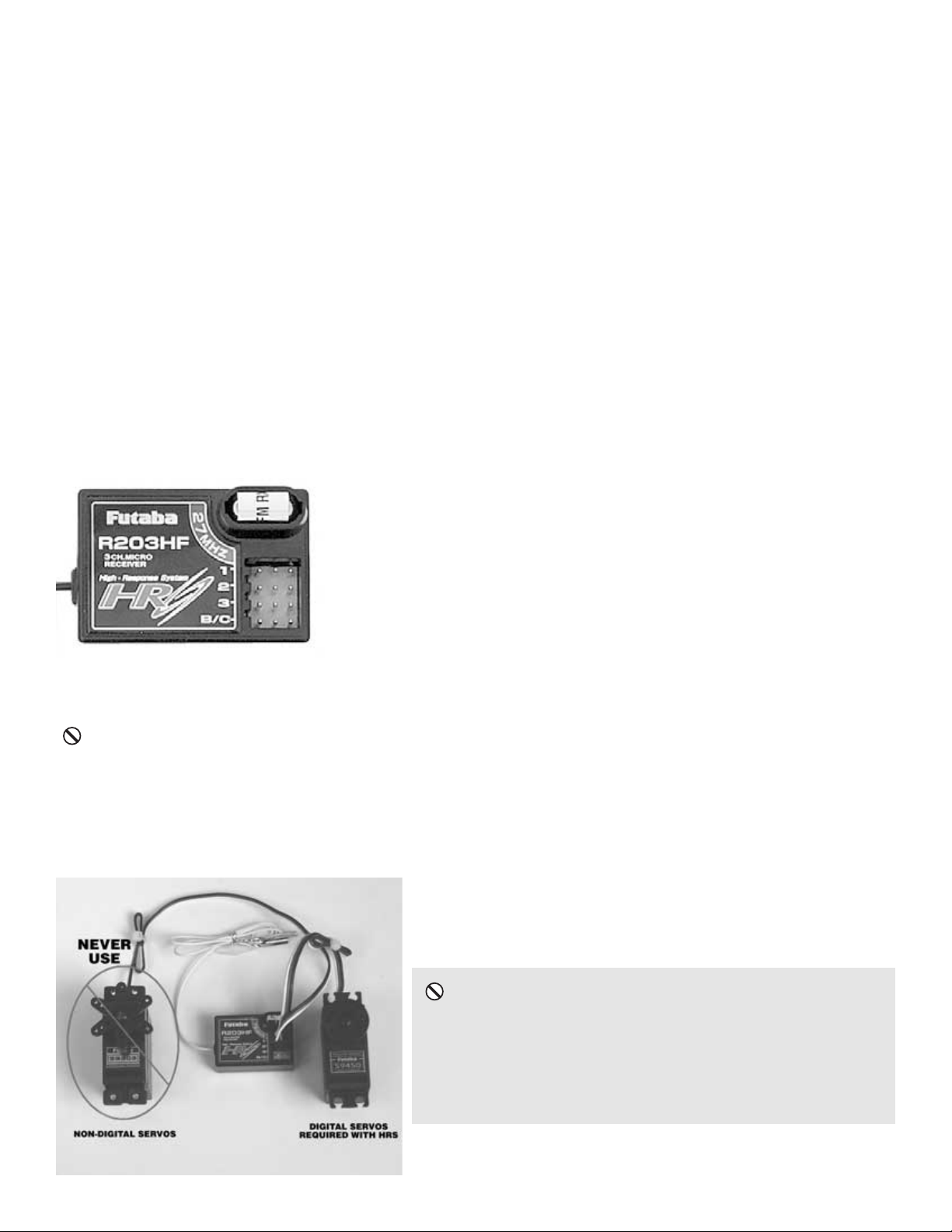
RECEIVER: R203HF or R113iP
•
The receiver included with your system is a high-sensitivity narrow-band
single-conversion receiver.
•
Any Futaba narrow band PPM(FM) receiver (all produced after 1991) on the
correct band and frequency may be used.
•
Any Futaba PCM 1024 receiver on the right band and frequency may be
used. (all 1024 receivers say PCM1024; receivers which say PCM but not 1024
are 512 resolution and not compatible).
•
Any Futaba HRS-FM receiver on the right band and frequency may be used. At
the time of this writing, only the R203HF is available. HRS receivers require 6.0V
batteries and digital servos, including for throttle.
•
In North America the receiver included with this system may have its frequency changed by simply changing the
crystal, as long as it remains in the same band. You may change anywhere from channel 61 through 90 in the 75MHz
band or A1 through A6 in the 27MHz band without requiring retuning.
NEVER attempt to change a receiver’s band by simply changing crystal (IE removing a 27MHz crystal and inserting
a 75MHz crystal). A receiver that has a crystal installed from a different frequency band without retuning will NOT
receive properly and will have dramatically decreased range if it responds at all.
SERVOS:
•
All Futaba PPM(FM) and PCM1024 receivers are compatible with all
J-plug Futaba servos, including retract, winch, standard and digital servos.
NEVER use non-digital servos with HRS
receivers. Severe damage to all electronics may
result, including the possibility of a fire. Only
digital servos may be used with HRS receivers,
including for throttle.
Page 8
8
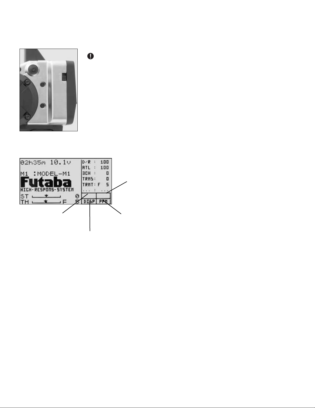
GETTING TO KNOW THE TRANSMITTER
Display switch
• If the display switch is turned on without turning on the power switch, programming is possible without emitting
radio waves.
If power switch is turned on while display switch is on, transmitter will transmit, which
will interfere with other users operating on the same frequency. Always be sure you have
control of your frequency prior to turning on the primary power switch.
• LCD screen contrast can be adjusted (See SYSTEM, p. 13.)
• LCD may be difficult to read due to temperature change when exposed to direct sunlight
for more than a few minutes at a time, extreme heat, cold, or humidity.
• Always use only the display switch unless you want to transmit to your receiver and you
have control of the frequency.
• Transmitting with the antenna collapsed may damage the module.
Power switch turned on: Beep confirmation sound is generated and the initial screen shown below appears.
• Total timer display (H:M) (see TIMER p. 30) and battery
voltage display
• Model name (10 characters) Futaba name can be changed to
display servo view or timers. (See SYSTEM, p. 13.)
• Steering trim display
• Throttle trim display
• Function names and rate assigned to dials/trims DL1-DL3 and
DT1-DT3 respectively.
• CAMPac, transmission, backlight and modulation status.
User name display: When the END button is held down for 1 second or longer at the initial screen, the Futaba logo and
user name are displayed for about 2 seconds.
BLHT
(if backlit)
DPAC
(if CAMPac installed)
RF (if transmitting)
DISP (if not transmitting)
PCM,
PPM
or
HRS
Page 9
9
Digital trim operation
•
Default assignments may be changed in FUNC-DIAL (pp. 34-35).
Features assigned to DL1, 2, 3, and DT1, 2, 3 are displayed at all
times on right side of LCD screen.
•
Digital trims can be used in 2 ways:
•
Operating by the lever: Push the lever to the left or right (up or down).
•
Operating by push button switch: Press the push button switch in
the desired direction.
•
The current position is displayed on the LCD screen in the bottom
three rows of the list.
•
Each step is indicated by a tone.
•
When the trim exceeds the maximum trim adjustment range, the beep
will change and the servo will not move any farther. Return to the
neutral position (center) by pressing both the push button switches
simultaneously for about one second.
•
Trim lever adjustments have no effect on the maximum servo travel.
This prevents the linkages from binding when adjustments are made.
Digital grip dial operation
•
Default assignments may be changed in FUNC-DIAL (pp. 34-35).
Features assigned to DL1, 2, 3, and DT1, 2, 3 are displayed at all
times on right side of LCD screen.
•
Initial settings: DL1=Steering Dual Rate, DL2=ATL
•
Operate the dials by turning them. The current set value is displayed
on the LCD screen.
•
A beep is made at each step.
•
When the maximum position is reached at each side, the length of the
beep changes. Thereafter, the set value does not change.
•
Remember, the dials are digital so the position of each dial is
remembered for each model separately.
Transmitter Checks Prior to Each Use
1. Turn on transmitter power.
2. Check the display screen for model name/number to
ensure you are working with the correct model.
3. Check the display screen for “RF”.
a. If RF is not displayed, check crystal/module installation.
Be sure module is clipped firmly into transmitter.
b. If RF is intermittent or non-existent, send for service
immediately.
4. Check the display screen for proper modulation to
match the receiver in this model.
a. FM receivers, such as R123F, must be set to PPM.
b. PCM1024 receivers, such as R113iP, must be set to PCM.
c. HRS-FM receivers, such as the R203HF, must be set to HRS.
5. Confirm function assignment. Notice the 6 features
listed in the box on the right of the screen, which shows
you the features assigned to the digital dials and digital
trims respectively, and their current settings.
6. Check trim, dual rate and ATL operation/positioning.
a. Steering trim is defaulted to the DT1 trim lever above
the steering wheel. Operate the lever and make sure
the marker moves on the ST graph. If default has
been changed, test steering trim in its new location.
b. Repeat test for throttle trim, defaulted to DT2.
c. Repeat test for steering dual rate, defaulted to DL1, at
the grip of the transmitter.
d. Repeat test for ATL, defaulted to DL2, below DL1.
DL1
DL2
Trim Lever
Trim Push
Button
Switches
Page 10
10
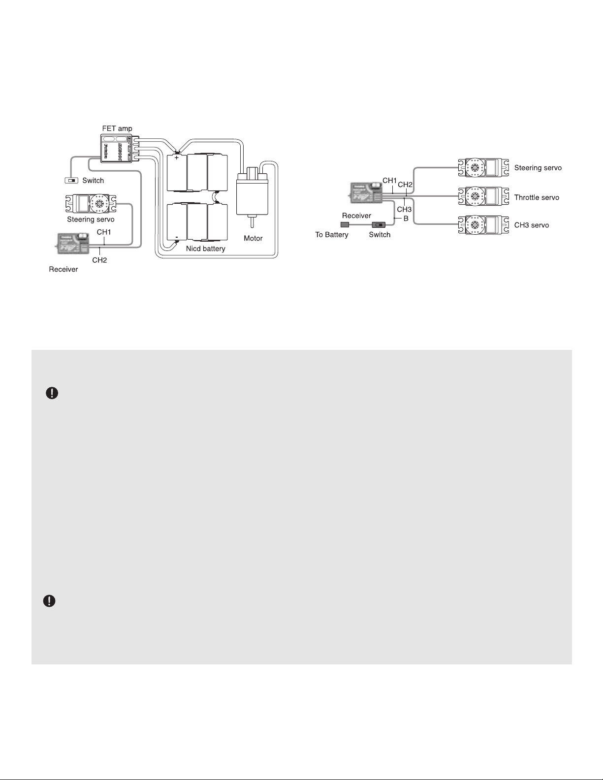
INSTALLATION
Receiver and Servo Connections
When connecting and installing the receiver and servos, read all safety precautions in the appendix.
Installation When an ESC is used (MC800C) Installation For Gas Powered Models
B/C port is for the receiver battery or a DSC cord. For information on DSC cord, see p 5.
Receiver Notes
DO NOT cut or fold the receiver antenna wire back on itself — cutting or folding changes the electrical length
of the antenna and may reduce range. Secure the antenna as instructed in your model's manual. You may run the antenna
inside of a non-metallic housing within the model, but range may suffer if the antenna is located near metal or carbon fiber
parts. Be sure to perform a range check before using.
When you insert Futaba servos, ESC, switch or battery connectors into the receiver, note that each plastic housing
has an alignment tab. Be sure the alignment tab is oriented properly before inserting the connector. To remove a
connector from the receiver, pull on the connector housing rather than the wires.
If your servos are too far away to plug into the receiver, use an extension cord to extend the length of the servo lead.
Additional Futaba extension cords of varying lengths are available from your hobby dealer. Always use an extension of the proper
length. Avoid plugging multiple extensions together to attain your desired length. If distance is greater than 18” or multiple or high
current draw servos are being used, Futaba Heavy-Duty servo extensions are recommended.
Receiver Vibration and Waterproofing
The receiver contains precision electronic parts. Be sure to avoid vibration, shock, and temperature extremes.
For protection, wrapping the receiver in foam rubber or other vibration-absorbing materials is ideal.
Mounting with double-sided tape is the next best option: It is also a good idea to waterproof the receiver by placing it
in a plastic bag and securing the open end of the bag with a rubber band. If you accidentally get moisture or fuel inside the
receiver, you may experience intermittent operation or a crash. If in doubt, send the receiver for service.
Page 11
Using the 3PK’s Functions:
The 3PK offers not only the most comprehensive menu of features available to provide optimum performance, but also
quick-access to utilize your favorite features. 3PK offers “Menu Selection” for onscreen lists of available features, and a
specialized, fully customizable version of “hot keys” called “Direct Selection.” (Don’t worry if terms seem overwhelming.
Check the glossary and read on to get more familiar with new terms.)
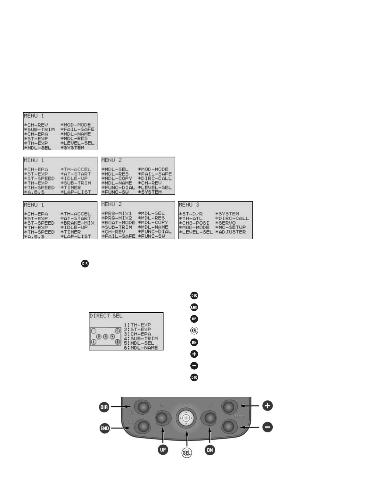
Menu Selection
•
Each function is easily selected from the function menu displayed on the LCD screen with the select key.
•
Three sets of function menus are available to match the level of use. To select the level for each model, use the Level
Select function (page 12). Note that functions are in different locations depending on the level selected. This is done
to keep level 1 simple, and keep related functions together on the higher levels.
•
Level 1 (LV1): For the new user, basic functions only.
•
Level 2 (LV2): Race-ready, including most popular racing
setup features.
•
Level 3 (LV3): All functions can
be selected. (For expert driver)
Direct Selection
•
The Direct Selection screen allows quick access to 6 user-selectable functions with just 2 keystrokes:
•
Press the key to open the Direct Selection Screen.
•
Press the button which corresponds to the feature’s number as shown on the on-screen diagram of the keys to
open that feature.
•
Direct Selection choices can be edited using the DIRC-CALL function (see p. 36).
11
Initial Settings
to Open
Throttle Exponential
Steering Exponential
End Point Adjustment (EPA)
Sub-trim
Model Select
Model Name
to Close
Page 12

A Look at the Radio’s Functions, Step by Step
LV1 FUNCTIONS for the New 3PK User and the Racers and Experts Alike
Level Selection LEVEL-SEL Levels LV1, LV2, LV3
DEFINITION: Selects the complexity of functions displayed on the menu screens.
Includes 3 levels of flexibility to simplify programming for new users and the
most flexible system in the world to those who wish to use it.
AVAILABLE FOR EACH INDIVIDUAL MODEL:
•
Selection of a lower level simply hides the higher level features from the menu;
however, setups in the higher level menus remain intact and as set prior to
changing the level.
•
Model reset clears all functions including those not visible in the displayed menus.
ADJUSTABILITY:
•
Level 1 (Learning the system; quick setups, a single menu with enough features for most models.) LV1
•
Level 2 (Expands upon Level 1 menu, with many race-ready features.) LV2
•
Level 3 (For the Expert driver, boat modeler, or other complex setups.) LV3
•
To view features available on each menu, see page 11.
DEFAULT: LV3
INTERACTION: NONE. Changing the complexity of what menu is visible has no effect on the programming whatsoever.
To adjust features set in a higher level and not currently visible, simply change the level back to the higher level and edit.
DESIRED END RESULT: Provide only as much information/access as needed without overwhelming the user with
features not currently desired.
CAUTION: Just because you change to a lesser level does NOT reset hidden functions to their defaults or to inhibited.
Be sure to inhibit any undesired functions and check settings which interact with other functions. (Example: throttle
ATL.)
12
GOAL:
Change setting from the default of Expert
Driver (LV3) to New User (LV1) to simplify
getting to know the basics of the radio. (If
on LV1 or LV2, scroll through menus, then
select LEVEL-SEL.)
Where next?
STEPS:
Open menu and display menu 3.
Select menu 3 & then select level
selection.
Select level 1.
Confirm your change.
Close.
INPUTS:
to LEVEL-SEL.
together for 1 second.
Screen displays LEVEL = LV1
Name the model (MDL-NAME): See p. 15.
Select modulation (FM/PCM/HRS) (MOD-MODE): See p. 16.
Channel reversing (CH-REV): See p. 18.
End point adjustment (ATV) (EPA): See p. 18.
Page 13

Levels LV1, LV2, LV3 System-Wide Settings SYSTEM
DEFINITIONS:
•
SYSTEM Adjusts system-wide settings. Settings are not model specific.
•
LHT-MODE LCD backlighting mode
•
LHT-TIME LCD backlighting time period
•
CONTRAST LCD screen contrast
•
BUZ-TONE Buzzer tone
•
LED-MODE LED pilot lamp
•
DISPL-SEL Home screen display settings
•
KEY-ON Back-lights whenever a programming key is pressed. Length of
time is adjustable with LHT-TIME.
•
ACT Activated.
•
SRV-VIEW Servo display shown on home screen.
AVAILABLE FOR: System-wide only. Not channel or model specific.
ADJUSTABILITY:
•
LCD backlight: OFF, KEY-ON, ON (constantly).
•
Backlight time period: OFF, ACT (when KEY-ON is selected in LHT-MODE).
•
1-30 seconds, length of time can be adjusted for backlight to stay on when a button (key) is pressed.
•
Screen contrast: -10 to +10.
•
Buzzer tone adjustment: OFF, 0-100.
•
Pilot lamp color: OFF, LIGHT BLUE, PURPLE, WHITE, GREEN, ORANGE, YELLOW, BLUE.
•
Home screen display: FUTABA, SRV-VIEW, TIMER.
INTERACTION:
•
When LHT-MODE is set to KEY-ON, backlight comes on automatically if any programming button is pressed, and time
period is automatically made ACT (active).
•
Pilot lamp blinks when key functions, such as ABS and speed limiter, are active.
DESIRED END RESULT: Custom setup to best meet user’s needs and style.
CAUTION: Adjusting display so dark/bright that it cannot be read and then turning transmitter off may require factory
service to reset.
13
GOAL:
Change the home screen display from
Futaba to timer while radio is in LV1 setting.
(If set to more complex menus, scroll
through menus with Up button until SYSTEM
is displayed on screen.)
Where next?
STEPS:
Open and select menu 1.
Select SYSTEM.
Select DISP-SEL.
Change to TIMER.
Close.
INPUTS:
to SYSTEM.
Adjust backlight settings (repeat steps above but edit LHT.)
Adjust screen contrast (repeat steps above but adjust CONTRAST.)
Set up timer function (TIMER): See p. 30.
Reset system timer (from home screen for 1 second.)
Page 14

Model Selection MDL-SEL Levels LV1, LV2, LV3
DEFINITION: Selects from the 10 model memories stored within the transmitter,
or additional model memories in the optional CAMPac ©.
AVAILABLE FOR:
•
10 models in transmitter memory
•
Optional additional memories, 10 per CAMPac © (see p. 5).
ADJUSTABILITY:
•
Models M1-M10 within the transmitter, E11-E20 from optional CAMPac ©
•
Stores complete model setups with all functions separate per model (except
settings within SYSTEM).
INTERACTIONS:
•
Each model memory is a completely separate setup, and allows adjustment of all functions within each separate
model memory (except SYSTEM functions).
•
Each model memory may be set to a different modulation. If a model memory of a different modulation is selected,
the transmitter must be turned off and back on to change the modulation.
•
Example: Model 1 is HRS with R203HF receiver. Model 2 is FM with R133F receiver. Select model 2 and
close the menu. Note that HRS is still displayed on screen. Turn transmitter off and back on. Modulation now
shows PPM and will communicate with the R133F or other FM receiver. (If you do not cycle the power on the
transmitter, it cannot communicate with the PPM receiver. See MOD-MODE, p. 16.)
•
Each separate model memory may have a different level selection, so that simple models have only LV1 menu, with
LV2 and LV3 for other, more complex models.
•
To make a copy of one model memory for setting up another, similar model, or for experimentation, change
LEVEL-SEL to LV2 (p. 12), and use MDL-COPY (p. 33).
DESIRED END RESULT: Select a specific model’s setup within the radio or CAMPac data storage.
CAUTIONS:
•
Never remove the CAMPac © with the power switch on.
•
If a CAMPac-stored model (E11-20) is in use when the transmitter is turned off, and then the CAMPac is
removed, “SELECT ERROR” will be displayed on screen and model M1 will be automatically selected. Use model
select to select the desired model.
•
The transmitter does not recognize one CAMPac as being different from another. Model E11 is the first model
in the CAMPac currently in the port, regardless of what CAMPac was last in the port. (Imagine inserting a
floppy disk into your PC with a file on it labeled car1.doc. Close the file, remove the floppy, and insert another
floppy which also includes a file called car1.doc. Your PC doesn’t know or care that they may be different files;
it simply opens the file named car1.doc.)
14
GOAL:
Select model M3, changing from model M1
and using the LV1 programming menus. (If
set to more complex menus, scroll through
menus with Up button until MDL-SEL is
displayed on screen.)
Where next?
STEPS:
Open and Select Menu 1.
Select MDL-SEL.
Choose M3.
Confirm your change.
Close.
INPUTS:
to M3.
together for 1 second.
Change menu to LV1 (LEVEL-SEL): See p. 12.
Name the model (MDL-NAME): See p. 15.
Copy the model (MDL-COPY): See p. 33.
Reset the model data (MDL-RES): See p. 32.
Select modulation (FM/PCM/HRS) (MOD-MODE): See p. 16. (Hint: remember to power
off and back on to begin transmitting in new modulation.)
Page 15

Levels LV1, LV2, LV3 Model and User Names MDL-NAME, USR-NAME
DEFINITION: Provides a 10-character name for each of the model memories in
the transmitter to easily select the correct setup for the model currently in use.
Also provides a 10-character user name that is constant to all model memories.
AVAILABLE FOR: M1-M10 in transmitter memory, E11-E20 if using optional CAMPac.
ADJUSTABILITY: Includes 0-9, A-Z and numerous symbols.
INTERACTIONS: Model name is reset to factory default with model reset, and
copied with model copy.
DESIRED END RESULT:
•
Clearly label each model for easy selection.
•
User name can be set to display on home screen (see SYSTEM, p. 13) for easy
confirmation of radio ownership.
CAUTIONS:
•
User name is constant across all model memories, so changing it changes it system-wide.
•
Model names may be the same between models; model # will still be displayed and will still be different.
15
GOAL:
Rename the current model FUTABA-1,
while using the LV1 programming menus. (If
set to more complex menus, scroll through
menus with Up button until MDL-NAME is
displayed on screen.)
Where next?
STEPS:
Open and select menu 1.
Select MDL-NAME.
Change first character to F.
Move to the second letter.
Repeat steps above to change name.
Close.
INPUTS:
7 times to F.
6 times to U.
16 times to T. Repeat.
Adjust the user name (USR-NAME): repeat steps above, but past model name to
user name and edit each character.
Copy the model (MDL-COPY): See p. 33.
Select modulation (FM/PCM/HRS) (MOD-MODE): See p. 16. (Hint: remember to power
off and back on to begin transmitting in new modulation.)
Channel reversing (CH-REV): See p. 18.
Page 16

Modulation Select MOD-MODE Levels LV1, LV2, LV3
DEFINITIONS:
•
Modulation select: Chooses the modulation (language) used by the transmitter to
give instructions to the receiver.
•
PPM: Pulse Position Modulation, commonly called “FM”. Transmitted via FM,
not encoded.
•
PCM: Pulse Code Modulation. Transmitted via FM, but encoded for increased
noise resistance. Includes FailSafe programming. (See p. 17.)
•
HRS: High Response System. Transmitted via FM at accelerated rate; includes
FailSafe programming. (See p. 17.)
•
FM: Type of transmission of data. (Similar to FM car radio.) Used for PPM,
PCM and HRS.
AVAILABLE FOR: Each individual model memory separately.
ADJUSTABILITY:
•
PPM (Pulse Position Modulation, commonly called “FM”) for FM receivers such as R133F
•
PCM (Pulse Code Modulation, 1,024 step resolution) for PCM receivers such as R113iP
•
HRS (High Response System) for HRS receivers such as R203HF
INTERACTIONS:
•
Modulation is set separately for each model. One model can be PCM and another HRS, and still another PPM(FM).
•
Modulation is not reset when a Model Reset is performed.
•
Modulation is stored for each specific model. Turn transmitter off/on if new model is in different modulation.
•
Both transmitter switches MUST be turned off and back on for a change to take effect. If transmitter is not turned off
after modulation is changed, it continues to transmit in the last modulation. Display shows the current method of
transmission under NOW OPERATION and the modulation that will be used as soon as the transmitter is turned off and
back on under MEMORY.
DESIRED END RESULT: Change transmitting “language” so the receiver can understand the transmitter’s instructions.
CAUTIONS:
•
While there are 3 types of modulation (4 if you include AM, not supported by 3PK), all are transmitted on the
same frequency band. NEVER attempt to operate more than one model on the same frequency at the same time.
•
Transmitter must be turned off and back on for change to take effect.
16
GOAL:
Change Modulation from HRS to PPM to
operate with standard Futaba FM receivers
such as R133F, while using model M1 and
the LV1 programming menus. (If set to
more complex menus, scroll through
menus with Up button until MOD-MODE
displayed on screen.)
Where next?
STEPS:
Open and select menu 1.
Select MOD-MODE.
Choose PPM.
Confirm your change.
Close.
Cycle transmitter power to transmit in
new modulation.
INPUTS:
6 times.
together for 1 second.
Turn both switches off.
Turn both switches back on.
Confirm screen reads PPM.
Name the model (MDL-NAME): See p. 15.
Copy the model (MDL-COPY): See p. 33.
Channel reversing (CH-REV): See p. 18.
End point adjustment (EPA): See p. 18.
Set up FailSafe reactions (FAILSAFE): See p. 17.
Change menu complexity (LEVEL-SEL): See p. 12.
Page 17

Levels LV1, LV2, LV3 FailSafe Settings FAIL-SAFE
DEFINITIONS:
•
FAILSAFE: Settings stored by the receiver, used only if the receiver fails to
receive clean, intelligible signal from a transmitter.
•
HOLD: Maintain the last instruction provided by the transmitter before clean
signal was lost.
•
SET: Position servos are to be moved to if FailSafe activates.
•
BATTERY F/S: When “on” the receiver will move the throttle servo to the preset
FailSafe position when the receiver battery is low. Release and pull trigger to
reactivate throttle for approximately 30 seconds.
AVAILABLE FOR Steering, Throttle, Channel 3, only with HRS/PCM receivers
and HRS/PCM modulation settings (see MOD-MODE, p. 16).
ADJUSTABILITY: Hold or set (to go to a preset position).
INTERACTIONS:
•
FailSafe operates only during interference or loss of transmitter signal.
•
Modulation is not reset when a model reset is performed, but the FailSafe settings are reset.
DESIRED END RESULT:
•
FailSafe: Provide receiver pre-recorded instructions of how to perform in the event it does not receive clean, clear
transmission from a transmitter on its channel in Futaba PCM1024 language.
•
Battery FailSafe: Warn user the receiver battery is getting so low that safe vehicle operation will soon end.
CAUTION: Settings are sent to the receiver every 2 minutes. Always allow at least 2 minutes’ time to pass prior to
testing any FailSafe settings.
17
GOAL:
Change FailSafe settings for your throttle
servo on your PCM receiver from
“HOLD” to full brake position, while
using the LV1 programming menus. (If set
to more complex menus, scroll through
menus with Up button until FAILSAFE
displayed on screen.)
Where next?
STEPS:
Open and select menu 1.
Select FAIL-SAFE.
Choose throttle channel.
Store desired throttle position.
Close.
Cycle transmitter power to test settings.
INPUTS:
5 times.
Hold T
HROTTLE TRIGGER to full brake.
together for 1 second.
Wait at least 2 minutes.
Turn master power switch off.
Observe response of throttle servo. It should
go to full brake setting.
Set battery FailSafe to obey stored FailSafe position in case of low receiver battery
voltage (BATTERY F/S): Repeat steps above but change MODE to ON.
Channel reversing (CH-REV): See p. 18.
End point adjustment (EPA): See p. 18.
Change menu complexity (LEVEL-SEL): See p. 12.
Set steering exponential (ST-EXPO): See p. 20.
Page 18

Channel Reverse CH-REV Levels LV1, LV2, LV3
DEFINITION: Reverses the direction the servo moves when given an input. If the
vehicle is turning right when wheel is turned left (or vice versa), reverse the
setting for the steering. If the engine accelerates when brake is pushed, reverse
the setting for the throttle.
AVAILABLE FOR: Steering, throttle, channel 3
ADJUSTABILITY: Normal, reverse
INTERACTION: Servo reversing affects all other functions, including EPA.
DESIRED END RESULT: Change the servo’s direction to exactly the opposite.
CAUTION: Servo reversing affects all functions, including ATL.
End Point Adjustment EPA Levels LV1, LV2, LV3
DEFINITION: End point, commonly called EPA or ATV, adjusts (shortens or
lengthens) the total travel of the servo. For example, a steering servo travels 60°
each way. Decreasing the right EPA to 50% results in a steering servo that will
move 60° to the left but only 30° to the right.
AVAILABLE FOR: Steering, throttle, channel 3.
ADJUSTABILITY: 0-120% on all 3 channels. Default: 100%.
18
GOAL:
When brake is applied, the engine
accelerates. Reverse the throttle servo
direction, while using the LV1 programming
menus. (If set to more complex menus,
scroll through menus with Up button until
CH-REV displayed on screen.)
Where next?
STEPS:
Open and select menu 1.
Select CH-REV.
Choose throttle channel.
Reverse the servo.
Close.
INPUTS:
End point adjustment (EPA): See p. 18.
Change menu complexity (LEVEL-SEL): See p. 12.
Set throttle exponential (TH-EXPO): See p. 20.
Set engine cut and smooth start features (AT-START): see p. 28.
Page 19

INTERACTIONS:
•
EPA is a primary function. EPA’s should be set prior to doing any other programming and not adjusted (except for
servo replacement, etc.) once other programming has been set. If EPA is adjusted after features such as dual rates,
ATL, mixing, etc, the other functions must be readjusted based upon the new EPA.
•
EPA is not limiting or absolute. Other programming functions can override the end point set by EPA. Always double
check for binding after adjusting:
•
Sub trim (all channels)
•
Program mixing slave side (all channels)
•
Tilt mixing (steering, channel 3)
•
Idle up (throttle)
•
Throttle preset (throttle)
•
ATL trim (set ATL trim dial center prior to adjusting throttle channel EPA.) (LV3 only.)
•
EPA is not tied to any mixing. EPA adjusts each individual servo regardless of brake mixing, boat mode mixing, etc.
NOTE: When EPA is increased to maximum (120%) but more servo travel is needed, the servo’s motion can be
increased with programmable mixing, up to the servo’s physical limits. (See programmable mixes, pp 40-41.)
•
Interaction Example:
•
Original setup:
•
Steering servo linkage allows 30° of servo rotation to the left.
•
Steering EPA is adjusted to 90%, creating 27° of left travel.
•
Steering dual rate is adjusted to 50%, or 13.5° of travel.
•
Adjusting EPA to 120% results in 36° of left travel; dual rate now provides 18° of travel, not 13.5°.
•
Steering dual rate adjusts the servo’s total travel as if EPA was adjusted. ATL adjusts braking travel. Both can be
assigned to dials (see FUNC-DIAL, pp. 34-35).
DESIRED END RESULT:
•
All channels: Servo is not binding or chattering, trying to move the linkage farther than it is physically able.
•
All channels: Servo moves the attached pushrod just enough, creating the desired maximum servo movement.
•
All channels: Linkage does not stick, bind, or catch on anything on the vehicle.
•
Steering: Full right and full left turns result in the desired turning radius.
•
Channel 3: Function moves the desired distance when full up/down, left/right or pressed/unpressed button are applied.
CAUTIONS:
•
Servo binding drains receiver batteries very quickly and may result in a loss of control.
•
More is NOT always better! Start with the desired steering throws recommended for your vehicle.
•
Always check for binding and servo “chatter” prior to each use.
•
Always set dual rates, sub trims, and all other functions to their defaults prior to adjusting EPA.
19
GOAL:
Change end point for steering servo so
servo arm does not strike chassis in right
turns, while using the LV1 programming
menus. (If set to more complex menus,
scroll through menus with Up button until
CH-EPA displayed on screen.)
Where next?
STEPS:
Open and select menu 1.
Select CH-EPA.
Go to steering channel right side setting.
Set desired end point (example 98%).
Close.
INPUTS:
to 98%.
Set sub-trim (SUBTRIM): See p. 22.
Set exponential (ST-EXP, TH-EXP): See p. 20.
Change menu complexity to access additional features (LEVEL-SEL): See p. 12.
Set idle-up (IDLE-UP): See p. 27.
Set anti-lock braking (ABS): See p. 24.
Page 20

Exponential (ST-EXP, TH-EXP) Levels LV1, LV2, LV3
DEFINITIONS:
•
Exponential adjusts the sensitivity of the servo around the neutral position.
Exponential creates a true curve, not a hard climb to a certain point then a softer
climb from there. Negative exponential makes the servo less responsive around
center; positive exponential makes the servo significantly more responsive
around center. Only exponential is available for steering and braking.
•
TH-EXP offers far more than just exponential for forward: it also offers a 5-point
throttle “curve” and a Variable Trace Rate (VTR) option.
•
VTR: Variable Trace Rate is basically a 3-point line, where one point may be
raised or lowered, forming two straight lines, and where the user can select the
point where the line breaks into two.
•
The “curve” function offers 5 points along the range of the servo, and draws
straight lines of response between each point. It is not a true curve, as is
exponential, and there are noticeable steps in the responsiveness as each rate of
response is entered.
20
Expo Curve
Expo Curve
Throttle Curve
(forward throttle only)
Variable Trace Rate (VTR)
(forward throttle only)
Page 21

AVAILABLE FOR: Steering (ST-EXP), Throttle (TH-EXP)
ADJUSTABILITY:
•
Range: -100% to +100%
•
Throttle: Forward and Braking
•
Steering: Left and right
•
Types: (TH-EXP forward only) Variable trace, curve, or exponential curves.
•
May be assigned to a dial for on-the-track adjustability. (See FUNC-DIAL, pp. 34-35.)
INTERACTIONS:
•
Exponential affects the servo’s response around center, and affects all built-in and programmable mixing functions
such as throttle acceleration, brake mixing, ABS, etc. All mixing functions respond based upon the position the
transmitter is telling the servo to go to, not the amount of trigger being pulled or wheel turned.
•
EPA affects the total travel of the servo, and exponential is proportional to and affected by that total travel.
•
AT-START, TH-SPEED, TH-ACCEL and other features interact with this function. For example, a very high VTR rate will
result in rapid acceleration early in the trigger movement. Therefore, the engine reaches wide open at, for example,
half throttle trigger. This may make it seem as though Speed Limiter programming is needed when you really should
adjust the VTR rate to create a more normal throttle response.
DESIRED END RESULT:
•
Positive exponential makes the servo move farther for the same amount of input when around neutral (for sharper
steering when small inputs are given, for example).
•
Negative exponential makes the servo move less for the same input when around neutral (to make a nitro engine’s response
to the throttle trigger smoother and more consistent between the first 1/4 of the trigger and the last 1/4 of the trigger.)
CAUTIONS:
•
Too much positive exponential can make the model so overly sensitive it may be impossible to control.
•
Too much negative exponential can make the model so non-responsive, your inputs may be too little too late,
resulting in a crash.
•
Too high of a rate on a throttle VTR will result in the engine reaching full throttle well before the trigger is at full
throttle, which may result in wheel spin, especially upon acceleration.
21
GOAL:
Making the steering servo less responsive
around center to get rid of oversteering
when trying to make corrections at high
speeds, while using the LV1 programming
menus. (If set to more complex menus,
scroll through menus with Up button until
ST-EXP displayed on screen.)
Where next?
STEPS:
Open and select menu 1.
Select ST-EXP (TH-EXP for throttle.)
Add negative exponential until servo is in
desired position.
Close.
INPUTS:
to –25%.
Create a throttle VTR with a rate of 0 and a trigger point of 50%. See how it is just a
straight throttle response? Now hold the throttle at 1/2 trigger while adjusting the rate.
See how increasing or decreasing the VTR will then cause the throttle servo to open
sooner, or slower, on a smoothly linear response?
Adjust braking expo for softer response around neutral. Repeat steps above in TH-EXP.
Set FailSafe (FAIL-SAFE): See p. 17.
Change menu complexity to access additional features (LEVEL-SEL): See p. 12.
Set speed of response for steering/throttle (ST-SPEED, TH-SPEED): See p. 23.
Set acceleration rate to avoid wheel spin (AT-START): See p. 28.
Page 22

Sub-Trim SUBTRIM Levels LV1, LV2, LV3
DEFINITION: Fine tuning adjustment for the center point of each servo. Similar to
using electronic trims on the radio, but subtrim moves the entire servo’s travel
rather than just sliding the servo left/right within the total travel. The setting is
stored within the programming and the onscreen displays continue to show neutral.
AVAILABLE FOR: Steering, throttle, channel 3
ADJUSTABILITY:
•
Steering: left 100 to right 100
•
Throttle: brake 100 to throttle 100
•
Channel 3: -100 to +100
•
May be assigned to a dial/trim. (See
FUNC-DIAL
, pp. 34-35.)
INTERACTIONS:
•
ALWAYS adjust your digital trims back to neutral prior to adjusting your subtrim. Then adjust the subtrim until the
servo is at the desired location without needing any digital trim.
•
Subtrim adjusts the entire range of the servo to one side or the other; it does NOT adjust the servo’s center point
toward one end of the total travel like digital trims.
•
Subtrim affects the neutral point for the servo for all other functions.
DESIRED END RESULT: Fine-tune the servo’s center point to correct for minor linkage problems.
CAUTION: The range of subtrim is limited. Always adjust linkages to get the servo’s center as close to the desired
location mechanically and only use trim functions as absolutely necessary.
22
GOAL:
Moving the steering servo arm one tooth
on the servo results in a slight right turn;
moving it back one causes a slight left
turn. Adjust the servo’s center (example:
5) so that the vehicle travels perfectly
straight with no steering input, while using
the LV1 programming menus. (If set to
more complex menus, scroll through
menus with Up button until SUB-TRIM
displayed on screen.)
Where next?
STEPS:
Open and select menu 1.
Select SUB-TRIM.
Cursor down to throttle and up to steering
to see the cursor positioning.
Add trim until servo is in desired position.
Close.
INPUTS:
to L5.
Set end point (EPA): See p. 18.
Set exponential (ST-EXP, TH-EXP): See p. 20.
Change menu complexity to access additional features (LEVEL-SEL): See p. 12.
Set idle-up (IDLE-UP): See p. 27.
Set throttle acceleration (TH-ACCEL): See p. 26.
Page 23

LV2 FUNCTIONS for the Race-Ready Driver
Levels LV2, LV3 Only Servo Maximum Speed Limiter (ST-SPEED,TH-SPEED)
DEFINITION: Speed Limiter decreases the maximum speed of the servo. This
may be adjusted individually for turning and returning the servo to neutral
(steering), and for high and low throttle settings.
A servo which responds too rapidly to a full-wheel input may cause the vehicle to
oversteer; to compensate many drivers steer too slowly, resulting in understeer
and not completing a clean corner. Others slow down to make the model more
controllable, losing valuable seconds. Speed Limiter helps in both these cases.
Similarly, applying throttle too suddenly results in wheel spin and wasted energy.
It may also cause a nitro engine to stall.
AVAILABLE FOR: Steering (ST-SPEED), Throttle (TH-SPEED)
ADJUSTABILITY:
•
1% (slowest possible response) to +100% (normal response)
•
On input and return (ST-SPEED only); High speed and low speed (TH-SPEED only)
•
On/off switch may be assigned for TH-SPEED only. Switch selection made in FUNC-SW (see pp. 34-35).
•
Throttle speed and steering turn/return may each be assigned to a dial. See FUNC-DIAL (pp. 34-35).
INTERACTIONS/COMPARISONS:
•
Increasing EPA decreases the rate at which a servo reaches a given point mechanically; therefore, adjusting EPA will
also adjust the actual rate of response of that servo.
•
Negative exponential softens how far the servo responds to a given input vs. how fast. Either is used to settle a
“twitchy vehicle”, but the driver must first determine if the servo is moving too far, or simply too quickly.
•
ABS pulsates the amount of brake given for a certain input to avoid overbraking and skidding the entire time brake
is applied. Speed Limiter slows the brake command and decreases skidding only when brakes are first applied.
•
Throttle acceleration gives a significant sudden movement of the throttle servo only when the trigger is first moved;
Speed Limiter would slow that quick step off idle and diminish the effectiveness of acceleration. Thus, modifying
Speed Limiter may require adjustments to acceleration, and vice versa.
•
Auto-start moves/holds the servo to a preset position when the throttle is applied the first time, then allows the servo
to operate through its normal travel for the rest of the run; Speed Limiter slows the performance of the throttle servo
at all times. If the problem is spinning on starts only, then auto-start should be adjusted, NOT Speed Limiter.
•
Idle-up increases the throttle idle as if throttle trim were applied, and is used to make starting nitro engines easier.
Speed Limiter will only effect how rapidly the engine responds when additional throttle is applied.
•
ATL adjusts the end point of the braking side only; Speed Limiter affects how quickly that total distance is traveled.
Adjustments to either may require fine adjustments to the other.
DESIRED END RESULTS:
•
Servo reaches actual travel commanded by trigger/wheel position, just at a more gradual rate.
•
Minimize wheel spin, harsh acceleration out of corners, understeering and spins.
23
GOAL:
Decrease throttle rate of response when
applying more than 40% throttle, to
minimize torque/spinning when accelerating
out of turns, while using the LV2
programming menus. (If set to LV3, select
TH-SPEED from menu 1). (If set to LV1, first
change level selection. See p. 12.)
Where next?
STEPS:
Open and select menu 1.
Select TH-SPEED. (use ST-SPEED to adjust
steering servo speed.)
Make active only above 40% trigger.
Decrease response speed to 50%.
Activate the function.
Close.
INPUTS:
to H40.
to 50%.
Assign on/off for throttle speed (FUNC-SW): See pp. 34-35.
Set ABS braking (ABS): See p. 24.
Page 24

Anti-Lock Braking ABS Levels LV2, LV3 Only
DEFINITIONS:
•
ABS: Simulates a full size car’s antilock braking by pulsing the brake on and
off rapidly.
•
ABP: Amount of brake return, how far the braking response is decreased
during the pulses.
•
DLY: Delay; determines how long the braking is applied before ABS begins
to operate.
•
CYC: Cycle speed adjustment, sets how rapidly the brakes cycle from full
brake to ABP and back.
•
TGP: Trigger point, sets at what point ABS will be activated. ABS does not
respond if less brake is provided than the trigger point setting.
•
DTY: Cycle duty ratio, sets the proportion of the total cycle spent with brakes
applied full vs. ABP.
•
STM: Steering mix setup, controls when the ABS is triggered based upon amount of steering input. Designed to
decrease skidding when vehicle is in a turn, and minimize spin outs.
AVAILABLE FOR: Braking only.
ADJUSTABILITY:
•
ABP: 0 (no ABS) to 100% [Servo goes to neutral (no brake) during pulse].
•
DLY: 0 (ABS responds immediately) to 100% (1.7 seconds of full brake before ABS takes over).
•
CYC: 1 (fastest) to 30 (slowest). Default=10.
•
TGP: 10-100.
•
DTY: -3 (longest full brake application — most likely to skid) to + 3 (shortest full brake – least likely to skid).
•
STM: OFF, N10-N100, E10-E100.
•
MODE:Inhibited, Active but switch is off, Active and switch is on.
•
Switch assignment can be changed in FUNC-SW (see pp. 34-35).
•
Each ABS variable can be assigned to dials in FUNC-DIAL (pp. 34-35) for on-the-course adjustability.
INTERACTIONS:
•
EPA, servo reversing, dual rates, Speed Limiter, acceleration, auto-start, and exponential all interact to create the
overall braking effect.
•
Brake mixing works with ABS as if only one brake servo were used. No second setup for ABS is required.
•
Trigger point, steering mix and assigned switch each control ABS. All three must “say OK” for ABS to respond.
DESIRED END RESULT: Model stops as rapidly as possible without skidding.
CAUTIONS:
•
Careful analysis of the problem causing skids is required to adjust the proper portion of ABS for best results.
•
Adjustments to EPA, auto-start, expo, speed, brake mixing, vehicle’s suspension, tire compounds, engine
tuning and ATL will all affect the performance of the ABS settings.
24
Page 25

25
GOAL:
Set up a fairly rapid servo (such as S9402)
on a nitro off-road vehicle, while using LV2.
(If using LV3, select ABS from menu 1.)
(If using LV1, first change level selection.
See p. 12.)
Desired settings:
Fairly mild return (ABP) 30%
Use ABS if brakes are applied for more
than approx. 1/4 second (DLY): 10%
Pulse quickly (CYCL): 5-7
Use ABS only if braking hard: TGP: 70%
Leave proportion of brake on to brake off
even (DUTY): 0
Leave steering mix off (STM): 0
View onscreen demonstration of braking
and make adjustments as needed.
Fine tuning:
Where next:
STEPS:
Open and select menu 1.
Select ABS.
Make ABS active.
Set rate of return to 30% (ABP).
Delay ABS coming on to 10% of the
maximum available delay (DLY).
Decrease the cycle value to increase the
cycle rate (CYCL).
Set the trigger position where ABS
becomes effective to 70% (TGP).
Leave the difference in brake-on to brakeoff in each cycle to 0 (DUTY).
Allow ABS to work whether vehicle is
turning or not (STM).
View ABS working within the function on
screen to confirm proper setup. (Hint: LV3
users can also view braking activity and
all other servo actions on screen using the
SERVO function.)
Close function and menus.
INPUTS:
to 30.
to 10.
to 5.
to 70.
(Leave at 0.)
(Leave at OFF.)
Gradually push the throttle trigger to
approximately half brake. Screen should
still read “MODE: ACT (OFF)”.
Push past 70%. Display now reads “MODE:
ACT (ON)” and you can see how brake
commands will be transmitted to the servo
right on the screen.
If brakes still lock during all stops, analyze the problem, then try:
Increasing ABP so less brake is applied during pulses.
Decreasing DLY so that ABS takes effect more rapidly.
Increasing CYC so the brakes pulse more rapidly, each on/off cycle is shorter.
Decrease the TGP so ABS takes over with less brake application.
Decreasing DTY so that brake off time is longer than brake on.
If brakes lock in turns but are not enough on straights:
Set STM so ABS functions only when turning (ex: E50).
NOTE: All of these functions interact with the throttle servo as well and are all interrelated. Adjusting any one may affect the performance of the others, as described in
Interactions for each function.
Adjust the throttle servo’s overall speed (TH-SPEED): See p. 23.
Adjust throttle exponential (TH-EXP): See p. 20.
Adjust throttle servo’s response only immediately around neutral to correct for nitro
engine’s lag due to linkage setup (TH-ACCEL): See p. 26.
Set up smooth acceleration off of the start or engine cut (AT-START): See p. 28.
Set up a high idle for starting/racing, and keep a normal idle to keep the car sitting still
on start line (IDLE-UP): See p. 27.
Adjust brake mixing for separate front/rear brakes (BRAKE-MIX) (LV3): See p. 42.
Page 26

Rapid Throttle Acceleration THR-ACCEL Levels LV2, LV3 Only
DEFINITION: Due to the shape of some nitro engine linkages, throttle servo
movement near neutral results in very little movement of the pushrod. Throttle
acceleration simply jumps the servo from neutral to a portion of the total
available throw whenever the trigger is moved away from center. It does NOT
change the speed of the servo; the servo will jump to the input position at its
maximum possible speed. Unlike exponential, which adjusts the whole throttle
movement into a curve, throttle acceleration simply “jumps” away from neutral
and then leaves the remaining response linear. Accelerate is a pre-programmed
VTR throttle exponential (see p. 20).
AVAILABLE FOR: Throttle and braking separately.
ADJUSTABILITY: 0-100%.
•
At 100% the throttle servo moves immediately to
approximately 40% of the total EPA.
•
At 100% the brake servo moves immediately to full brake.
•
Each setting may be assigned to a dial or trim for on-thetrack adjustability. (See FUNC-DIAL, pp. 34-35.)
INTERACTIONS:
•
EPA will affect how far the servo moves in the jump. Changes in EPA may require adjusting throttle acceleration.
•
Brake mixing works with acceleration as if only one brake servo were used. No second setup is required.
DESIRED END RESULT: Model responds to throttle/brake immediately, similar to an electric car.
CAUTION: High brake settings will result in locked brakes. Adjust throttle acceleration only enough to pick up the
slack in the linkage; then, utilize ABS to fine tune braking performance.
26
GOAL:
Remove throttle and braking “lag” due to
linkage in a 4WD nitro powered car, while
using LV2. (If using LV3, select TH-ACCEL
from Menu 1.) (If using LV1, first change
the level selection. See p. 12.)
Where next:
STEPS:
Open and select menu 1.
Select TH-ACCEL.
With receiver on, adjust forward until the
linkage opens the carb with the slightest
throttle input.
With receiver on, adjust brake until the
linkage applies brake with the slightest
brake input.
Close function and menu.
INPUTS:
6 times
as needed.
as needed.
NOTE: All of these functions interact with the throttle servo as well and are all interrelated. Adjusting any one will affect the performance of the others.
Adjust the throttle servo’s overall speed (TH-SPEED): See p. 23.
Adjust throttle exponential (TH-EXP): See p. 20.
Setup ABS braking (ABS): See p. 24.
Set up smooth acceleration off of the start or engine cut (AT-STAR T): See p. 28.
Set up a high idle for starting/racing, and keep a normal idle to keep the car sitting still
on start line (IDLE-UP): See p. 27.
Adjust brake mixing for separate front/rear brakes (BRAKE-MIX) (LV3): See p. 42.
Page 27

Levels LV2, LV3 Only Idle-Up IDLE-UP
DEFINITION: Adjusts the throttle’s idle/neutral point, usually used to create a
raised idle, making it easier to start the engine. May adjust either toward higher
idle (U) or toward braking (D).
AVAILABLE FOR: Throttle only.
ADJUSTABILITY:
•
D50-1, 0, U1-50%. D = brake side. U = throttle side.
•
Rate may be assigned to a dial or trim for on-the-track adjustability (see FUNC-
DIAL, pp. 34-35).
INTERACTION:
•
Requires switch assignment in the FUNC-SW screen (see pp. 34-35).
•
EPA does NOT affect the preset position of idle-up.
•
Idle-up could actually exceed your total EPA. Idle-up obeys only the actual total servo travel and servo reversing, and
no other programmed changes.
DESIRED END RESULT: Throttle servo moves to a preset position when button is pushed and throttle trigger is at
idle. Has no effect at other throttle positions.
CAUTION: If you have to adjust your EPAs after setting up this function, be sure to double check that the pre-set
travel is still what is desired.
27
GOAL:
Set a high idle of 25% of servo travel to get
engine to start easily even when warm
from racing, while using LV2 programming
(If LV3, select IDLE-UP from menu 1). (If
using LV1, first change the level selection
to LV2. See p. 12.)
Where Next:
STEPS:
Set desired switch (FUNC-SW).
Open and select menu 1.
Select IDLE-UP.
Set desired rate to up (increase) 50%.
Test function on screen.
Close function and menu.
INPUTS:
See FUNC-SW (pp. 34-35).
to U 50%.
Press selected switch (ex: PS-1).
Note screen now reads “ON” and LED
blinks. Release switch.
NOTE: All of these functions interact with the throttle servo as well and are all interrelated. Adjusting any one will affect the performance of the others.
Adjust throttle EPA (EPA): See p. 18.
Adjust the throttle servo’s overall speed (TH-SPEED): See p. 23.
Adjust throttle exponential (TH-EXP): See p. 20.
Setup ABS braking (ABS): See p. 24.
Set up smooth acceleration off of the start or engine cut (AT-START): See p. 28.
Adjust brake mixing for separate front/rear brakes (BRAKE-MIX) (LV3): See p. 42.
Page 28

Auto-start Throttle Settings and Engine Cut AT-START Levels LV2, LV3 Only
DEFINITIONS:
•
Auto-start: A pre-set throttle position, less than full throttle, to be used for the
initial acceleration off the line without having wheel spin. When the trigger is
released, auto-start is turned off and throttle operates normally again.
•
ATS: Auto-start status.
•
Engine Cut: Shuts the engine off without having to adjust the throttle trim. Takes
the throttle servo to a preset position when the switch is pressed. (Not available
to models using braking/reverse from the throttle servo. Primarily for boats.)
•
TG.P: Trigger point at which auto-start is activated.
•
PRST: Preset throttle servo position when function is activated. Preset is a
“true” preset – it is not a mix or a portion of the EPA. It is truly a
command to move the servo to a set position regardless of other inputs,
including trigger.
•
MODE: Which function is being utilized at this time. (Engine cut and auto-start can not be used together).
•
AT&SW: Auto-start is activated by throttle trigger or switch. Switch can be assigned in FUNC-SW (pp. 34-35) and
used to turn on/off the auto-start feature without having to pull or release the throttle trigger to do so.
•
INH: Inhibited. Function is electronically inhibited and will not operate until changed to another setting.
•
SW: Switch operated. Auto-start is inhibited and engine cut is available. (Assigned in FUNC-SW, pp. 34-35.)
AVAILABLE FOR: Throttle servo only.
ADJUSTABILITY:
•
MMOODDEE
: Inhibited, switch only (engine cut), auto-start with switch override (autostart).
•
AATTSS
: Inhibited, off (not available until set), ready (will activate on next trigger pull), active (operating now).
•
TTGGPP
: Inhibited, 5-95. Default: 5.
•
PPRRSSTT
: Brake 100-1, 0, Forward 0-100. Default: 0.
•
Auto-start may be assigned to a switch. Engine cut must be assigned to a switch to operate. (See FUNC-SW, pp. 34-35.)
INTERACTIONS:
•
EPA has NO effect on the preset position. The preset position may exceed EPA. Be sure to set auto-start after setting EPA.
•
Servo reversing DOES change the direction of the preset in this function.
•
No other function affects the preset except servo reversing.
•
Trigger position has no effect on engine cut. Engine cut will shut engine to the preset position regardless.
•
Auto-start must be restarted for each use by going to the auto-start function and pressing the + and – keys together
for one second while ATS is selected, or assigning and holding on a switch. (See FUNC-SW, p. 34-35.)
•
If throttle triggered, auto-start remains active once started until the throttle trigger is returned to neutral.
DESIRED END RESULT: Avoiding wheel spin on starts and shutting engine off safely.
CAUTION: Remember that preset is not relative to EPA, so always check for binding if other changes have been made.
28
Page 29

29
GOAL:
Set auto-start to avoid wheel spin, while
using LV2. (If using LV3, select AT-START
from menu 1.) (If using LV1, first change
the level selection, see p. 12.)
Example: Trigger point of 95% so that any
acceleration other than wide open off the line
will not trigger the auto-start feature.
Preset of 54% (determined on the track
that this is the maximum acceleration you
can have off the line without spinning.)
Where Next:
STEPS:
Open and Select Menu 1.
Select AT-START.
Select Auto-start mode.
Set pre-set position for throttle to go to
when auto-start is in use.
Set trigger point to activate auto-start.
Activate auto-start to be used on next full
acceleration.
Test function on screen.
Set desired end point (example 98%).
Close function and menu.
INPUTS:
to AT&SW.
to F54.
to 95.
to READY.
Pull trigger slowly until past 95%.
* displays at TGP.
ATS indicates ACT, MODE indicates ON.
Release trigger. ATS returns to OFF.
Press to re-activate.
Set up engine cut: Set mode to SW, set preset. You must also set cut switch in FUNC-SW
(pp. 34-35.)
Assign a switch to AT-START using FUNC-SW (p. 28), then test auto-start using switch
instead of trigger.
Adjust the throttle’s total travel (EPA): See p. 18.
Adjust the brake’s available travel/trim (TH-ATL)(LV3): See p. 37.
Adjust the throttle servo’s overall speed (TH-SPEED): See p. 23.
Adjust throttle exponential (TH-EXP): See p. 20.
Set up ABS braking (ABS): See p. 24.
Set up a high idle for easier engines starts (IDLE-UP): See p. 27.
Adjust brake mixing for separate front/rear brakes (BRAKE-MIX) (LV3): See p. 42.
Exper
t Tip
: If you set up a switch in FUNC-SW (see pp. 34-35) assigned to auto-start,
you can use that switch to turn on/off the Auto-start feature without having to go to the
95% throttle position.
Page 30

Timers TIMER Levels LV2, LV3 Only
DEFINITIONS:
•
Total Timer: System timer, does not
reset/change with model selection, or
when transmitter is turned off, storing
total use time until it is reset.
•
Racing Timer: Model-specific timer; types:
•
Up Timer: Regular stop watch timer.
Counts up from 0 until stopped.
Runs consecutively until reset with
model selection or lap reset.
•
Down Timer: Count-down timer.
Counts negatively once desired time
is passed (below 0). Runs consecutively until reset with model selection or lap reset.
•
Lap Memory Timer: Acts as a count-up timer, storing each lap and starting a new lap each time button is pressed,
while also maintaining a total run time count-up alarm, with a pre-alarm warning time. Stores up to 100 laps,
visible on LAP-LIST (see p. 31). Has a 3-second safety window where button press does not reset the lap.
•
Lap Navigate Timer: Count-up timer which alarms at a set total run time, but also has a navigation alarm which
alarms every set interval (desired lap time), and then restarts the navigation alarm countdown on each button press
or upon passing each navigation alarm time. (Example: 4 minute track race, desired lap time is 30 seconds. Nav
alarm goes off if lap counter is not pressed before 30 seconds, then again after another 30 seconds, and so on until
4 minutes.) Great for practice-runs and working toward a target track time. Does NOT store individual lap times.
•
LAP START: Switch assignment required to indicate start/stop, or the end of each lap in lap navigate and lap memory timers.
•
LAP RESET:Switch assignment required to end timers and reset them to be used again.
•
RUN: Timer is currently running, and displays total run timer, tracking total race time regardless of individual laps.
•
STP: Timer is stopped.
•
RST: Timer reset. Stops running timer, resets run timer, stores last lap to memory.
•
RDY: Trigger-ready state. If set to ready, timer begins with trigger pull, doesn’t require lap start button to be pressed
to begin timer; however, lap button still needs to be pressed to store each lap. Trigger activity has no effect after
starting the timer.
•
LAP: Current lap number.
•
No.: Number of laps stored and ready to display.
•
TIME: Current running lap time.
•
NVALM: Number of times the navigation alarm went off, indicating you exceeded your target lap time.
•
ALRM: Total run time prior to desired alarm.
•
PRAL: Pre-alarm, warning that desired time is approaching, beeps once every second until alarm time is reached.
AVAILABLE FOR: N/A
ADJUSTABILITY:
•
Timer types: See 5 timer types listed above (including total timer).
•
System Time: 0 to 99 minutes 59 seconds. Resets to 0 at 100 minutes.
•
Status: Reset (timer is reset, button will start), ready (throttle trigger or button starts), run, stop.
•
Alarm: Off, 1-99 minutes. Default = 4 minutes.
•
Pre-Alarm: Off, 1-30 seconds, warning that alarm is about to sound. Beeps every second. Default = 5 sec.
•
Lap: Navigate timer only: 3 seconds to 30 minutes, interval counter to nav. alarm. Default = 3 seconds.
•
Switches: Assign lap start/stop and reset buttons in FUNC-SW (see pp. 34-35).
INTERACTION:
•
Requires switch assignment in the FUNC-SW screen. (See pp. 34-35.)
•
Laps stored with a lap memory timer are visible using LAP-LIST. (See p. 31.)
DESIRED END RESULT: Provide user accurate time data for tracking laps, practicing, keeping track of fuel and battery
usage, etc.
CAUTION: Lap Memory has a 3-second safety. If button is re-pressed within 3 seconds, the timer is not reset a second time.
30
Page 31

Levels LV2, LV3 Only Lap Listing LAP-LIST
DEFINITION: Displays all stored lap times, up to 100, and also stores total race
time, including run time after last but before reset/stop.
ADJUSTABILITY:
•
Reset single lap: Select lap, cursor blinks next to it. Press together.
•
Reset all laps in memory: Press and together for 1 second.
INTERACTION:
•
Requires switch assignment for lap counter in the FUNC-SW screen (see pp. 34-35).
•
Requires set up of timer as Lap Memory Timer (see p. 30).
•
Lap Navigation Timer does NOT store lap times (see p. 30).
DESIRED END RESULT: Store multiple lap times to analyze performance after the race.
31
GOAL:
Set up a lap memory timer to track lap times
throughout a race, while using LV2 menus.
(If using LV3, select timer from Menu 1). (If
using LV1, first change level selection to
LV2. See p. 12.)
Where Next:
STEPS:
Assign desired lapstart and restart switches.
Open and select menu 1.
Select TIMER.
Set type to lap memory timer.
Set total race time to 5 minutes.
Set pre-alarm time to warn you race end is
nearing at 15 seconds.
Set total timer/first lap timer to trigger
when throttle is pulled.
Test function on screen.
Close function and menu.
INPUTS:
See FUNC-SW pp. 34-35.
to LAP MEMORY.
to ALRM. to 5m.
to 15s.
Screen reads RDY.
Pull trigger. Timer starts counting.
Press selected switch (ex: PS-1) to store
first lap.
Note screen now displays the first lap’s
time for 3 seconds, then displays current
running lap.
Press selected reset switch to stop timer.
System timer: Reset radio’s total timer after recharging to use as a method of tracking
on time between charges: from home screen, press and hold for one second.
View stored laps (LAP-LIST): See p. 31.
Adjust switch assignments (FUNC-SW): See pp. 34-35.
Place timer setup screen on quick menu for 2-keystroke access (DIRC-CALL): See p. 36.
GOAL:
View laps previously run, then reset all laps,
while using LV2. (If using LV3, select LAP-LIST
from menu 1.) (If using LV1, first change
level selection to LV2, p. 12.)
Where Next:
STEPS:
Open and Select Menu 1.
Select LAP-LIST.
Scroll through laps shown on screen.
Reset all laps to prepare for next practice.
Close function and menu.
INPUTS:
or as needed.
and together for 1 second.
Change timer type to lap navigate timer (laps will not be stored) (TIMER): See p. 30.
Adjust timer settings (TIMER): See p. 30.
Change switch assignment to start/stop lap timer (FUNC-SW): See pp. 34-35.
Page 32

Model Reset MDL-RES Levels LV2, LV3 Only
DEFINITION: Erases all data stored in a specific model memory.
AVAILABLE FOR: Current selected model only. Model # is displayed on screen.
INTERACTIONS:
•
Resets settings for the specific model memory currently in use without resetting any
settings for any other model in memory.
•
Model reset does not reset:
•
Modulation;
•
System settings;
•
Adjuster;
•
Lap listings;
•
User name;
•
Direct selection menu setup.
•
Model copy may be used prior to model reset to store a copy of this data, including to an optional CAMPac.
DESIRED END RESULT: Delete all existing programming from this model memory only.
CAUTIONS:
•
Deleted data can not be restored.
•
See list of functions NOT reset with a model reset under interactions.
32
GOAL:
Reset all data in Model #M3, while
already in model M3, and using the LV2
programming menus. (If using LV3, select
MDL-RES from menu 2.) (If using LV1, first
change level selection. See p. 12.)
Where Next?
STEPS:
Open and select menu 2.
Select MDL-RES.
Confirm your change.
If desired, return to LV1.
Close.
INPUTS:
for 1 second.
Name the model (MDL-NAME): See p. 15.
Copy the model (MDL-COPY): See p. 33.
Select a different model (MDL-SEL): See p. 14.
Select modulation (FM/PCM/HRS) (MOD-MODE): See p. 16. (Hint: remember to power
off and back on to begin transmitting in new modulation.)
Channel reversing (CH-REV): See p. 18.
Page 33

Levels LV2, LV3 Only Model Copy MDL-CPY
DEFINITION: Makes an exact copy of the current model, including its name.
AVAILABLE FOR: Current selected model only. Model # is displayed on screen.
ADJUSTABILITY: N/A
INTERACTION: Copies all settings, including model name, modulation, etc.
DESIRED END RESULT: Make an exact copy of a model for backup, to copy to
CAMPac to use in another radio, etc.
CAUTION: Any existing model data in the model memory copied INTO will be lost.
33
GOAL:
Copy model M1 into model M3, while
already in model M3 and using the LV2
programming menus. If using LV3, select
MDL-COPY from menu 2.) (If using LV1, first
change level selection to LV2. See p. 12.)
Where Next:
STEPS:
Open and select menu 2.
Select MDL-COPY.
Select the model # to copy INTO.
Confirm your change.
Close
INPUTS:
to M3.
for 1 second.
Name the model (MDL-NAME): See p. 15.
Select a different model (MDL-SEL): See P. 14.
Select modulation (FM/PCM/HRS) (MOD-MODE): See p. 16. (Hint: remember to power
off and back on to begin transmitting in new modulation.)
Page 34

Function Placement/controls FUNC-DIAL, FUNC-SW Levels LV2, LV3 Only
DEFINITIONS:
•
Function: Assigns functions to the 3 dials,
3 trimmers, and 3 switches on the radio.
Upper right on home screen displays
assignments to dials 1-3 and trims 1-3.
•
PS: Push button switch. Also called switch,
or SW. PS1 = SW1
•
ALT: Push button setting: push once
for on, push again for off.
•
NOR: Push button setting: hold for
on, release for off.
AVAILABLE FOR: Digital Dials 1, 2, 3 (DL 1-3); Switches 1-3 (PS 1-3), Digital Trims 1-3 (DT1-3). See transmitter
image (inside front cover) for locations of each dial, switch and trimmer.
ADJUSTABILITY:
•
Step amount can be adjusted for all dials/trimmers.
•
Trim functions (ST-TR, TH-TR): Increasing step decreases sensitivity of each click. Setting of 1 = 200 clicks for
entire trim range; setting of 10 = 20 clicks for entire trim range. Range = 1-7,10. Default = 1.
•
Channel 3: Adjustable to perform like a 2- or 3-position switch, as well as a range of sensitivity. Setting of
1 = 200 clicks; setting of 50 = 4 clicks. Range = 1, 2,5,10,20,50, 3PS (3-position switch), 2PS (2-position
switch). Default = 1.
•
All Other Functions: Step is the percent of the total value of that function changed by a single click.
Range = 1-7,10. Default = 1.
34
Available Functions
Dual rate; 2nd dual rate
AT L
Exponential (steer/forward/brake)
Speed (steer turn/return; throttle)
ABS (return/delay/cycle)
Acceleration (forward/brake)
Trim (steer/throttle)
Channel 3
Sub-trim (throttle/steer/ch 3)
Idle-up
Tilt mix (1>3/3>1)
Programmable mix (left/fwd/up;
right/brk/dwn) (mix 1/2)
Brake mixing (rate/delay/balance)
No function assigned
Auto-start
Throttle speed
ABS
Idle-up
2nd dual rate
Channel 3
Programmable mix 1/2
Lap start/reset
No function assigned
Abbreviation on setup screen
D/R; D/R2
ATL
EXP-S/EXP-F/EXP-B
SPDT/SPDR ; THSPD
ABSP/ABSD/CYCLE
ACC-F/ACC-B
ST-TR/TH-TR
CH3
SBT-1/SBT-2/SBT-3
IDLUP
TLT13/TLT31
PM1-A/PM1-B; PM2-A/PM2-B
BK-RT/BK-DL/BK-BL
OFF
AT-START
TH-SPEED
ABS
IDLE-UP
D/R 2nd
CH3
PROG MIX 1/PROG MIX 2
LAP START/LAP RESET
OFF
Abbreviation on home screen
D/R; D/R2
ATL
EXPS/EXPF/EXPB
SPDT/SPDR; THSPD
ABP; ABSD; CYCL
ACCF/ACCB
TRMS/TRMT
3CH
SBT1/SBT2/SBT3
IDLE
TL13/TL31
PM1A/PM1B; PM2A/PM2B
BKRT/BKDL/BKBL
OFF
N/A
N/A
N/A
N/A
N/A
N/A
N/A
N/A
N/A
ALL DIALS/TRIMMERS:
ALL SWITCHES:
 Loading...