

Page 1
The
FP
G154/G134
stabilisation is accomplished by detecting angular acceleration with the rate gyro. Detected
motion information is fed to the control amplifier, which then sends a counteraction signal to the
appropriate control surface.
is a single
axis
rate
gyro
designed
to
stabilize
FEATURES OF FP G154/G134
aircraft.
Like
full
size
aircraft,
• The FP G 154 is for Futaba J M, F and SG Series
(1520 us neutral) digital proportional radio control sets.
• The FP.G134 is for Futaba E, F. G, H and L Series
(1310 us neutral) digital proportional radio control
sets.
• The gyro body and control amp are small, making
mounting very easy.
•The
gyro sensitivity can be
the gyro output trimmer at the control amp.
• Direction of correcting mix can be switched at the
control amplifier (internal reverse amp switch).
easily
adjusted
with
• A very sensitive magnetic motion sensor with
excellent voltage characteristics, linear sensitivity,
high speed response is used. This results in superior neutral characteristics. Such characteristics
make it ideal for use with the rudder channel of a
model helicopter or in the aileron/elevator channel of a model aircraft.
• Large 2mm diameter gyro motor shaft for long
life and strength.
• The gyro motor only can be turned on and off by
gyro power switch.
Page 2
RATINGS
Power supply voltage
Current drain
Dimensions and weight
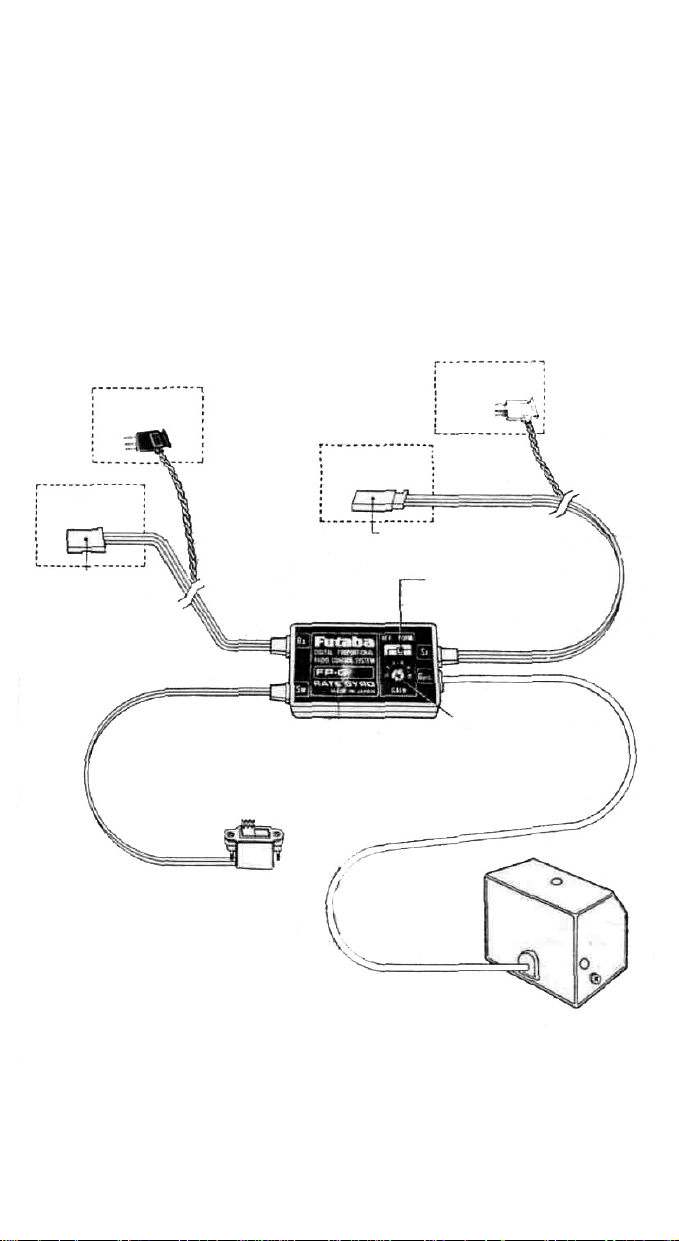
CONNECTIONS
(A) Connector
G134
(A) Connector
G154
Connect to receiver channel
10 be stabilized
(rudder channel for
helicopter)
Black
4.8V
shared
with
rece
iver
Motor: 100mA, Amplifier: 20mA (at 4.8V)
Gyro body: 1.57 x 1.65 x 1.60 in. (42 x 34 x 39mm)
Control amplifier: 1.06 x 1.89 x .63 in. (27 x 48 x 16mm)
Gross weight: 3.6 oz.
(B) Connector
(102g)
G154
Connect 10 the servo
(rudder servo for helicopter)
Gyro direction
reverse switch
(B) Connector
G134
White
Gyro power switch
Control amplifier
Gyro output trimmer
By using the gyro output trimmer
you may adjust the sensitivity
between 0% and 100%.
Gyro body
Page 3

RATE GYRO INSTALLATION
NOTE: Be sure gyro is mounted as shown; for stabilization of the correct axis.
Helicopter • For
Connect connactor (A) to the receiver rud-
der channel and connector [B ] to the rudder
servo.
Aircraft - For
Connect connector (A) to the receiver aileron
channel and connector IB) to the aileron
servo.
Aircraft - For
Connect connector (A) to the receiver el-
evator channel and connector (B) to the elevator servo.
-When
the gyro
this
situation,
recheck its direction of operation,
INSTALLING THE GYRO BODY
• The best mounting position is at the center of
gravity of the aircraft; however, it may also be
installed a short distance away from the center
of gravity.
•
Install
the gyro where there
tion.
•
Attach
the
adhesive tape.
gyro to the
rudder
use
aileron
use
elevator
(pitch
is
mounted 180
switch the internal
is
little
fuselage
shaft)
out
of phase, the
reverse
engine vibra-
with
use
amp
double-side
direction
switch
of
the correcting mix
to
"REV".
After
CONTROL AMPLIFIER INSTALLATION
• Install the control amp where there is little engine
vibration,
• Attach the control amp with double-side adhesive
etc.
tape.
mounting
will
the
be
reversed.
gyro
To correct
to
the fuselage,
UK double sided adhesive
tape
(Clean the mounting sur
face and stick the gyro to
the with soft double-side
adhesive tape.
Use soft double-side
adhesive tape about 3mm
thick and 10mm wide.
Double-side adhesive tape
Attach with soft double-side
adhesive tape.
Us* soft double-side adhesive tape about 3mm thick
and 10mm wide.
Page 4
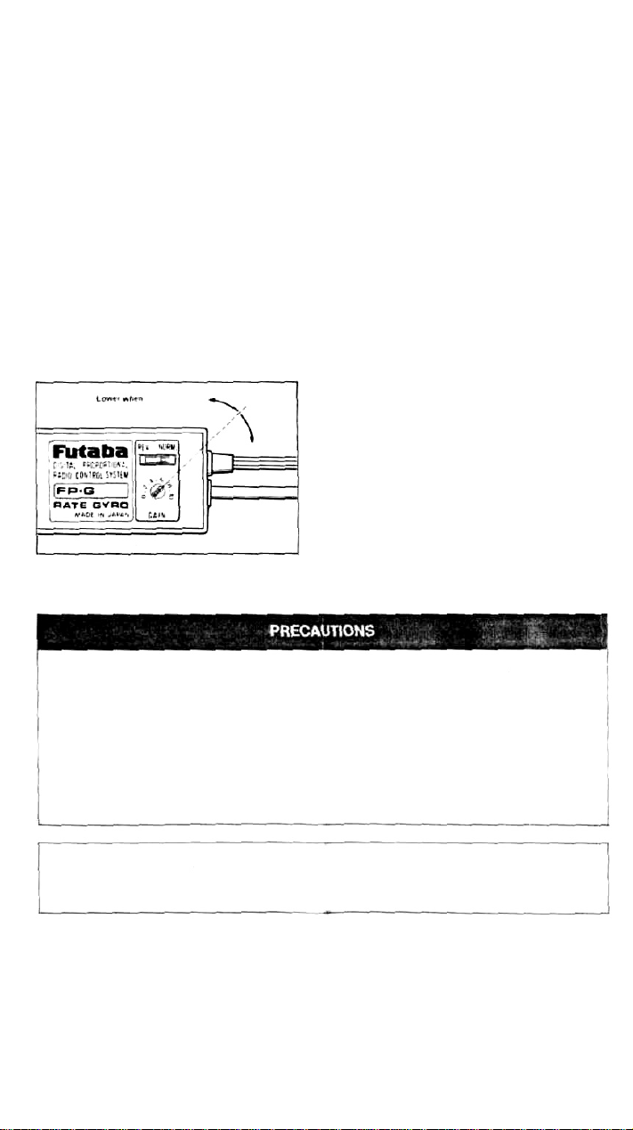
EXAMPLE OF GYRO ADJUSTMENT
WHEN MOUNTED IN A MODEL
HELICOPTER.
• Set the gyro output trimmer to graduation 7 using
a small flat blade screwdriver.
• Adjust the output trimmer so that tail (rudder)
hunting does not occur when hovering with helicopter fuselage facing the wind and when turning
and flying straight ahead.
• If hunting does occur then lower the sensitivity by
reducing the gyro output trimmer. When you
sense that gyro sensitivity is low then increase
gyro output trimmer to desired sensitivity.
Low when hunting occurs
Gyro
output increases
Control amp.
POWER SUPPLY
•The
G154/G134
supply as the receiver and servos.
•When the receiver and gyro use a common power
supply, rudder/servo power consumption and the
power consumed by the gyro, increases the total
power consumption. This decreases the number of
permissible flights. The use of a high capacity
(4.8/1,000mA) Nicad battery is recommended
(The Futaba NR-4LB (4.8V/1,000mA) Nicad bat-
tery pack can be purchased separately.)
Rate
Gyro
uses
the
same
power
•Do not expose the rate gyro to shock and vibration
•Do not disassemble or modify the rate gyro
When the imide of the gyro must be inspected, remove
the three screws on the side of the case and remove the
cover.
Do
not
loosen
the
screws
on
the
bottom
of
case.
• When the gyro output trimmer is set to zero, the
gyro sensitivity becomes zero.
When requesting repair after long use, accident, or
if any other trouble has occurred, describe the
problem in as much detail as possible. This will
the
• When the gyro power switch is set to OFF, only
the gyro motor is turned off. At this time, since
the control amp operates and the connected
servos may be operated by fuselage vibration.
When flying, always set the gyro power switch to
ON.
• When a gyro output switching function is required, such as in competition, etc., purchase the
G153/G133 or G153BB/G133BB from your
local Futaba dealer.
allow us to isolate the trouble point quickly and
reduce the repair time.
 Loading...