

Page 1
The FP-G153/G153BB/G133/G133BB is a single axis rate
gyro designed to stabilize aircraft. Like full size aircraft,
stabilisation is accomplished by detecting angular acceleration with the rate gyro. Detected motion information is fed
to the control amplifier, which then sends a counteraction
signal to the appropriate control surface.
•A very sensitive magnetic motion sensor with excellent
voltage characteristics, linear sensitivity, high speed
response is used. This results in superior neutral characteristics. Such characteristics make it ideal for use with the
rudder channel of a model helicopter or in the aileron/
elevator channel of a model aircraft.
•Large 2mm diameter gyro motor shaft for long life and
strength.
•The
highest
bearing. (G153BB/G133BB only)
quality
ball bearing
is
used
as
the motor
•The FP-G153/G153BB is for Futaba J, M, and SG
Series (1520 us neutral) digital proportional radio control
sets.
•The FP-G133/FP-G133BB is for Futaba E, F, G, H. and
L Series digital proportional radio control sets.
•Voltage regulated gyro motor supply maintains constant
motor speed and allows consistent gyro performance. The
voltage regulator is effective only when used with an external 6V. (five cell Nicad battery).
•Direction of correcting mix can be switched at the control
amplifier (internal reverse amp switch).
•Centering of the channel being stabilized can be adjusted
by a neutral trimmer built into the control amplifier.
•The gyro can be bypassed without affecting normal operation by
•Gyro output ("sensitivity") can be switched to one of two
preset outputs at the transmitter (use the retract switch if
possible, or any avail, channels).
turning
the gyro power switch
"off".
Page 2
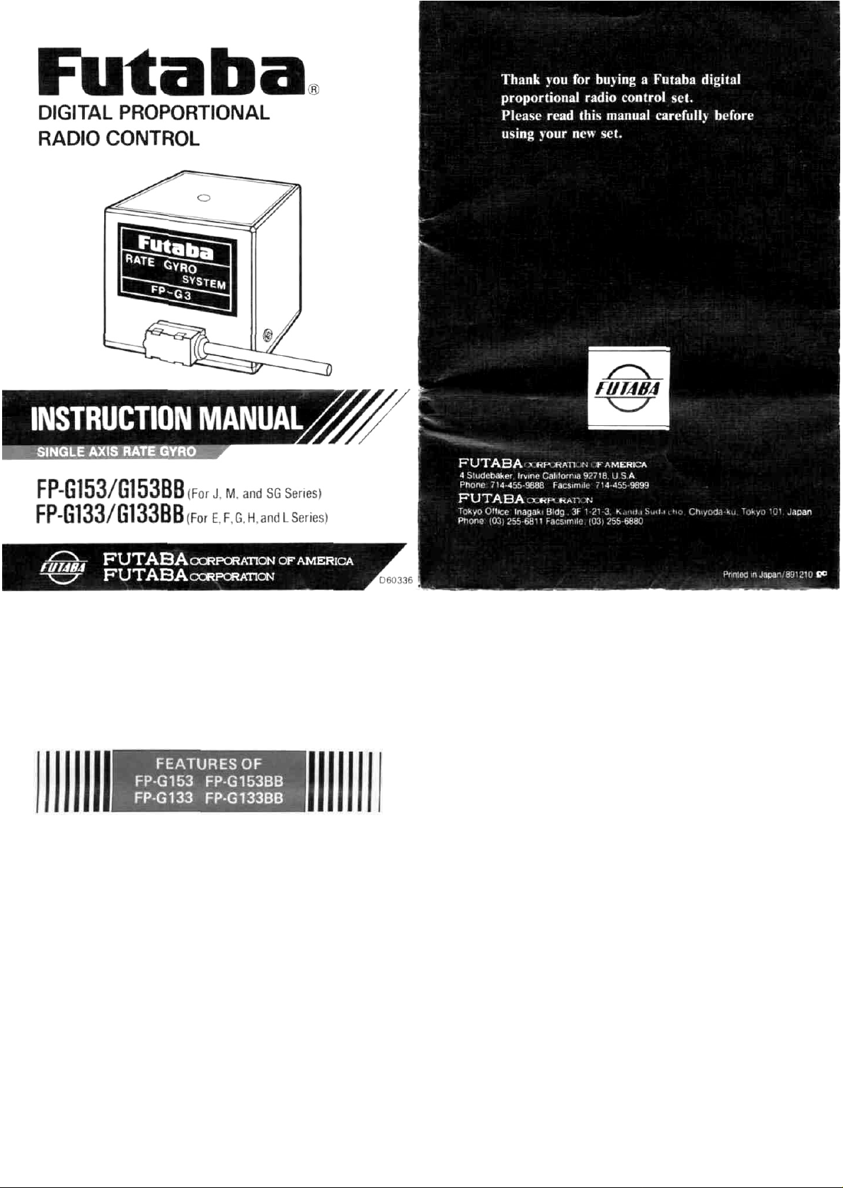
OUTPUT ADJUSTMENT
•When using the switchable gyro output sensitivity feature,
connect connector (B) to the retract channel if possible.
However, a proportional channel can be used. The output
sensitivity switching point will then be at the center or
neutral area.
*When the transmitter landing gear switch is pulled for-
ward (or down), the output sensitivity can be adjusted
from 0 to 100% with trimmer (1).
*When the transmitter landing gear switch is pushed
back (or up), the output sensitivity can be adjusted
from 0 to
mers (1) and (2) do not interfere with each other, and
can be adjusted independently.
•When the output is fixed or there is no spare channel (as
with 4 channel set), do not connect connector (B). In this
case, adjust the output with control box trimmers (1) and
(2). (Insulate the terminals with vinyl tape so they cannot
be touched.)
100%
with
trimmer
(2).
In this
case,
trim-
EXAMPLE
Adjustment when installed in a helicopter:
When using the switchable output sensitivity:
Set trimmer (1) to about the 80% of maximum output sensitivity position (100% is full clockwise) as a starting point.
Hover
with
the
wind
and readjust
hunting" does not occur. However, do not reduce output
sensitivity to a point where the nose will turn upwind when
"lifting off".
Set trimmer (2) to about the 60% position when a large
rudder travel is unnecessary, such as 540° stall turns, etc.
trimmer
Approx. 60%
(1)
so
that
Approx. 80%
"tail
*When trimmer (1) is 0, the output can be adjusted
from 0 to 50% with trimmer (2).
*When trimmer (1) is 100%, the output can be adjusted
from 50 to 100% with trimmer (2).
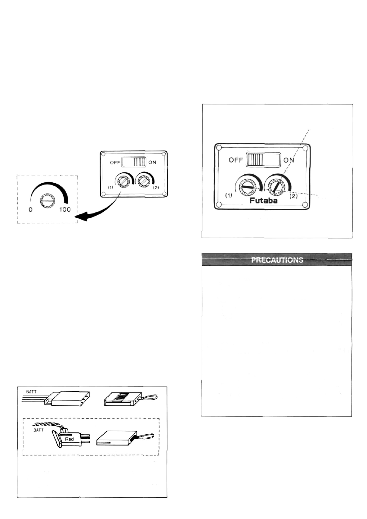
POWER SUPPLY
•When using the rate gyro with a separate power supply
(utilizing the motor voltage regulator), connect the five
cell Nicad battery pack (6V) to connector (C). Thereby,
maintaining constant motor speed and consistent gyro
performance. A four cell Nicad (4.8V) battery pack cannot be connected to connector (C).
•Whenever a four cell Nicad battery pack (4.8V) is used, it
must be as a common power supply for the receiver and
gyro. Connect the accessory jumper connector to connector (C), when using a 4.8 volt power supply.
•When the receiver and gyro use a common power supply,
rudder/servo power consumption and the power con-
sumed by the gyro, increases the total power consumption.
This decreases the number of permissible flights. The use
of a high capacity (4.8/1,000mA) Nicad battery is recommended. (The Futaba NR-4I (4.8V/1000mA) Nicad battery pack can be purchased separately.)
(C) connector
Jumper connector
Control box
•Do not expose the rate gyro to shock and vibration
•Do not disassemble or modify the rate gyro
When the inside of the gyro must be inspected, remove
the three screws on the side of the case and remove the
cover. Do not loosen the screws on the bottom of the
case. If these screws are loosened, the neutral position
may change at sensitivity or polarity switching.
•This gyro is not interchangeable with other
gyros or control amps.
When requesting repair after long use, accident, or
if any other trouble has occurred, describe the
problem in as much detail as possible. This will
allow us to isolate the trouble point quickly and
reduce the repair time.
FP-G133/G133BB
(C) connector
Connect the following to the (C) connector (control amplifier BATT):
* Five cell Nicad battery pack (6V) Our optional NR-5PB
(6V/450mAH) Nicd battery pack, etc. is recommended.
* Jumper connector, when the gyro and receiver use a com-
mon power supply
Jumper connector
Page 3

RATE GYRO INSTALLATION
NOTE: Be sure gyro is mounted as shown; for stabilization of the correct axis.
Helicopter - For
Connect connector (A) to the receiver rudder channel and connector (D) to the rudder
servo.
rudder
use
Aircraft - For aileron use
Connect connector (A) to the receiver aileron
channel and connector (D) to the aileron
servo.
Aircraft
Connect connector (A) to the receiver elevator channel and connector (D) to the elevator servo.
• For
elevator
(pitch
shaft)
use
•When the gyro is mounted 180° out of phase, the
direction of the correcting mix will be reversed.
To correct this situation,
switch the internal reverse
amp switch to "REV".
After mounting the gyro
to the fuselage, recheck
its direction of operation.
INSTALLING THE GYRO BODY
•The best mounting position is at the center of gravity of
the aircraft; however, it may also be installed a short distance away from the center of gravity.
•Install the gyro where there is little engine vibration.
•Attach the gyro to the fuselage with double-side ad-
hesive tape.
Use double-sided adhesive
tape
(Clean the mounting surface and stick the gyro to
it with double-side adhesive tape.)
Use double-side adhesive
tape about 3mm thick and
10mm wide.
INSTALLING THE CONTROL BOX
Using the control box nameplate as a template, drill four
holes and cut an opening for the slide power switch. Mount
the control box on the fuselage, away from engine exhaust
and where there is minimal vibration.
-Pan head tapping screw(2)
2x8
Switch box nameplate
Switch box (top)
Switch box (bottom)
•Wrap the control amplifier in sponge, to prevent vibration
problems.
Page 4

RATEINGS
Power supply voltage
Current drain
4.8V shared with receiver (6V for external supply)
Motor: 100mA, Amplifier: 20mA (at 4.8V)
Dimensions and weight
CONNECTIONS
(B) Connector
G133/G133BB
White
Connect to receiver
retract or auxiliary channel
(for gyro sensitivity switching)
Gyro body: 1.57 x 1.65 x 1.60 in. (42 x 34 x 39mm)
-
2.86
oz
Control amplifier: 1.73 x 2.28 x .63 in.(44 x 58 x 16mm) - 1.61 oz.(45g)
Control box: .94 x 1.34 x .59 in. (24 x 34 x 15mm) -
Connection connector
(Can be connected/disconnected in the arrow direction.)
Connected servo (rudder servo for helicopter)
neutral trimmer (this trimmer is operative even
when the control box power switch is off).
.54oz.(15g)
(69g)
Gyro
body
(B) Connector
(A) Connector
G133/G133BB
(A) Connector
Gyro direction
reverse switch
Black
Connect to receiver channel
to be stabilized
(rudder channel for helicopter)
Control amplifier
Special 6V five cell Nicad battery
pack connector for motor regulated power supply. (Insert the
jumper connector when a shared
power supply is used.)
Connect to the servo (rudder servo for helicopter)
Gyro power switch
Gyro output trimmer
(C) Connector
Jumper connector
(C) Connector
G133/G133BB
(D) Connector
Black
The G153/G153BB and G133/G133BB are interchangeable by changing the connectors and
readjusting the neutral trimmer.
(D) Connector
G133/G133BB
 Loading...