

Page 1
Futaba
DIGITAL PRO PORTI ONAL
RADIO CONTROL
PCM1024ZA
PCM1024ZH
PULSE CODE MODULATION SYSTEM
Page 2

Thank you for purchasing
a Futaba digital proportional radio control set.
Please read this manual carefully
before using your set.
ATTENTION:
1. Application of Product
This product is not intended for use in any application other than for the
control of models for hobby and recreational purposes. This product is
subject to regulations of the Ministry of Radio/Telecommunications and is
restricted under Japanese low to such purposes. The laws of other countries
may similarly restrict the use of this product. Futaba is not
responsible for any use that is not in compliance with applicable law.
2. Exportation of Product
If the product is exported from Japan, the prior approval of the Ministry of
Radio/Telecommunications is required regarding the country of destination.
If this product is reexported from other countries, it may be subject to
restrictions on such reexport and prior approval of government authorities
may be required.
3. Modification, Adjustment & Replacement of Parts
Futaba is not responsible for any use of this product that is not in
compliance with applicable law and disclaims all responsibility for any modification or alteration of the product, including the incorporation of the product into other products by third parties, that is not in compliance with applicable law.
ATTENTION:
The product that you have purchased contains a rechargeable battery.
The battery is recyclable. At the end of its useful life, under various state
and local laws, it may be illegal to dispose of this battery into the
municipal waste stream. Check with your local solid waste officials for
Ni-Cd
THE FOLLOWING STATEMENT APPLIES TO THE RECEIVER
This device complies with part 15 of t he FCC Rules.
Operation is subject to the following two conditions:
(1) This device m a y not cause harmful interference, a n d
(2) This device must accept any interference received,
details in your area for recycling options or proper disposal. (For U.S.A.)
including interference that may cause undesired operation.
(For U.S.A.)
Page 3

TABLE OF CONTENTS
Manual Introductory Section
System Features
Introduction
System
Manual Layout
FLYING SAFETY
Notable System Features
PCM 1024Z System Contents. ..............
Power-On Screen Displays
Working With The CAMPac Memory Module .....
Using
The
Operation Without Radio Transmission .........
System Monitor Lights & Warnings ............
System Status and Alarm Displays ............
Using Your Futaba System Contents. . .........
Radio Installation
Charging & Direct Servo Connect Operation .....
Stick Length Adjustment
Stick Tension Adjustment .................
Stick Angle Adjustment ..................
Antenna Angle Adjustment ................
Transmitter Battery Replacement ............
Rubber Protective Pad Installation ............
Transmitter RF Module ..................
Synthesized Frequency
Flight
Condition
SYSTEM MENU
Contents ...........................
MSL - Model Selection
VLT - Battery Voltage Display. ..............
TAC - Tachometer .....................
SR V - Servo Cycl e & Bar Graph Display .........
TRN - Trainer System ...................
DTN - Data Transfer Function ..............
CPM - Copy Model Function ...............
CPC - Copy Condition
PAR - Parameters (Sets Auto-Off and
Screen Contrast) ..................
UNA- User Name Registration ..............
FRO - Trans. Freq. Set ..................
Setting The Frequency Synthesizer Receiver ......
SWT - Switch setting ....................
MODEL SETTING SECTION
Contents........................... 39
CSL - Condition
TIM - Timers & Elapsed Time Counter .........
F/S - Failsafe/Hold Setting ................
PMD - Pulse Mode FM/PCM ................
REV -Servo Reversing Function .............
FNC - Function
RST - Data Reset ......................
CUT - Engine Cut .....................
CHD - Condition
TY P - Model Type Selection ...............
CH 9- Channel 9 Switch Definition ...........
MNA - Model Name Definition ..............
ALT - Alternate Switch ..................
THR - Throttle Curve ...................
SWH -Swashplate Type ..................
RDR - Rotor
INV - Inverted Pitch ....................
PIT - Pitch Curve ......................
COMMON CONDITIONS
Contents...........................
ATV - Adjustable travel volume & Channel delay ...
AFR - Adjustable
D/R - Dual rates & EXP
......................
........................
Usage
........................
.......................
.....................
.................
Soft
Keys
....................
.....................
.................
Module & Receiver
Switching
...................
Function
Select
..................
Control
..................
Hold
...................
Direction
..................
function
curve.
.................
................
.............
rate
..............
..............
......
2
3
4
6
7
9
11
.12
1
1
.18
19
21
21
35
.99
23
94
95
26
97
93
99
30
31
39
33
34
35
36
37
40
41
42
43
44
45
46
47
48
49
50
51
52
53
54
56
57
58
59
60
62
64
Manual Introductory Section, Page 1
PMX - Programmable
STM - Subtrim
TOF - Trim
CNA - Condition
TRM • Digital
10
3
14
14
15
16
7
19
20
20
AIRPLANE SECTION
Table of Contents
Airplane Controls & Functions
Airplane
Receiver
Airplane Setup Instructions
Aileron
Differential [ADF]
Rudder Coupling
V-Tail [VTL]
Rudder—Aileron
Elevons [EVN]
Elevator-»Flap
Flap-Elevator
Collective Pitch [CPT]
Ailvators
[ALV]
Flaperons [FPN]
Airbrake [ABK]
Snap Ro ll
Throttle Curve
HELICOPTER SECTION
Table of Co nten ts
Helicopter Controls
Helicopter Receiver and Servo
Sample Helicopter Setup Instructions
Pitch
Hovering Pitch [PHV] ...................105
Pitch Trim [PTM] .....................106
Throttle Curve [TCV]
Hovering Throttle [THV] .................108
Hovering Offset [HOF] ..................109
Throttle Hold [H LD] ...................110
Swashplate
Pitch—Rudder [P—R] .................. .112
Rudder—Throttle
Gyro Sensitivity [ GY R] ..................114
Acceleration [ACC]
Inverted Pitch [INV] .................. .117
SAILPLANE SECTION
Table of Contents
Sailplane Condition Menus ................119
Sailplane Transmitter Controls and Functions . . . .
Sailplane
Example Sailplane Setup Instructions ..........
Aileron Differential [ADF] ................
Aileron—Rudder Mixing
Aileron-Speed Flap Coupling [ASF] ..............................
V-Tail [VTL] .......................
Airbrake
Elevator—Brake
Elevator—Speed Flap
Brake Flap Mixi ng [BKF]
Speed Flap Mixing .....................
Speed
Butterfly Mixing [BFY] ..................
Butterfly
Elevator
Trim Mix 1 [TM1] & Trim Mix 2 [TM2] - 4-S .....
Flap-Elevator
Elevator-Flap Mix [E—F] ................. .143
Flaperon Mixing (FPN] -
COMMAND
[SNP]
Curve
Receiver
Mixing
Flap
Trim
Trim
mixing
.......................
offset
.....................
naming
trim
.....................
.....................
and Servo
[A—R]
........................
[R-A]
.......................
[E—F]
mix
[F—E]
......................
......................
......................
......................
Adj.
.....................
[PCV]
....................
Type
[SWP]
[R—T]
....................
and Servo
[ABE]
Flap Mixing [EBF]
Trim
[SFT]
Mix [BYE]
(ETM)
mix
[F—E]
LIST
.....................
...............
.................
..............
Connections
................
................
.................
.................
...................
.................
..................
(TCV)
................
....................
Connections
..................
...................................111
.................
........................................
Connections
[A-R].
............
..................
Coupling
..................
...................
................
............. . 130
(ESF)
..................... . . .132
................
2-S
............... 149
........
.......
..........
......
.........
65
68
69
70
71
73
74
76
77
80
81
32
83
84
85
86
37
33
39
91
93
94
95
96
93
99
.104
.107
.11
115
. 118
.120
.121
195
125
.126
127
.128
129
.131
135
139
140
142
143
145
..147
151
3
Page 4

Manual Introductory Section
Futaba's PCM 1024Z series of radio control systems is the most sophisticated available for aircraft, helicopters, and sailplanes.
Inside this radio is the logic necessary to
control virtually any aircraft imaginable
(both transmitter types are programmed
for all three aircraft).
System Features:
• 1024 High resolution system
• 9 Channels (select channel
• 10-Model Memory
• 8-Character Model names
• 16 added memories with CAMPac Module
• Up to 8 flight conditions for each model
• 5 programmable mixers with special advanced
functions for each model setup
• Each flight condition separately programmable
• Flight condition & channel delay setting
• Ready for aircraft, helicopters, and sai lplanes
• Deluxe carrying case included
• Carrying handle
• Ergonomic shape easy to hold
• Attractive neckstrap and mount
• Ball bearing control sticks
• Adjustable tension control sticks
• Adjustable length control sticks
• Adjustable angle control sticks
• Programmable transmitter switches
• Large liquid-crystal display
• Contrast adjustment
• Soft keys make programming simple
• Switchable FM/PCM
• Optional synthesized frequency
receiver
• Unique Digital Trim function (2 rates)
•
Electronic
volume, exponential
• Failsafe/Hold setting
• Powerful data copy functions
• Swiveling antenna stores in
• Detachable battery pack
• Two separate timers & elapsed
• Automatic system power-off
• Low-voltage alarm
• Special Mixer alarm
• Voltmeter with adjustable load for transmitter
and receiver batteries
• Built-in tachometer
• DSC System
• Trainer system
servo
centering, reversing,
order)
and operate
module &
throw
transmitter
time counter
Built into the system are a number of
menus designed to make it simple to tailor
the system's programs for YOUR aircraft.
Multiple menus provide unparalleled control of every aspect of the model's setup,
even some that you probably never thought
of before!
Airplanes
• Aileron Differential
• Rudder Coupling [AS-R]
• V-tail [VTL]
• Rudders-Aileron
• Elevons [EVN]
• Elevators-Flap [E-F]
• Flaps-Elevator [F-E]
• Collective pitch [CPT]
• Differential elevators [ELV]
• Flaperons [FLP]
• Airbrake [ABK]
• Snap Roll [SNP]
• Throttle Curve Adj. [TCV] (12 segment)
Helicopters
Pitch Mixing [PCV]
Hovering Pitch [PHV]
Pitch Trim [PTM]
Throttle Curve [TCV]
Hovering Throttle [THV]
Hovering Offset [HOF]
Throttle Hold [HLD]
Swashplate type [SWH]
Pitch-Rudder [P-R]
Rudder-Throttle [R-T]
Gyro Sensitivity [GYR]
Acceleration [ACC]
Inverted Pitch [INV]
Throttle curve adj. [THR]
Rotor Direction [RDR]
Sailplanes (Select from2,4, or 5-servos in wing)
• V-tail [VTL]
• Differential adjustment
• Rudder coupling [A-R]
• Aileron-flap coupling [ASF]
• Airbrake/Spoiler/Gear trim
• Elevator-flap coupling [EBF, ESF]
• Flap trim setting [SFT]
• Butterfly (Spoileron or Crow)
• Butterfly trim mix [BYE]
•
Elevator
• Flap-Elevator mix [F-E]
• Elevator-Flap mix [E-F]
• Flaperon mixing [FLP]
trim
sets
[ADF]
[R-A]
[ADF]
compensation [ABE]
[BFY]
[ETM]
Manual Introductory Section, Page 2
Page 5

INTRODUCTION
Manual Introductory Section
Thank you for selecting the Futaba®
PCM1024Z Radio System. The design of
this system has absolutely no compromises.
You now possess a system that will allow
you to fly your model — airplane, helicopter, or sailplane — with the highest per-
formance possible. With a // the power in
this system, setting up and adjusting is very
simple. We recommend that you read the
manual carefully to learn about the programming features, but if you are in a hurry, follow the example set-up instructions
in the beginning of the model setup procedures sections. We have provided detailed
examples for power aircraft, helicopters,
and sailplanes (with two, four, and five
wing servos).
The transmitter can be used with any
model type by using the desired special
mixing menus for the model you are interested in — a / / menus are contained in both
types of transmitters. The transmitters for
airplanes and sailplanes (PCM 1024ZA)
contain
different throttle stick feel than the heli-
copter system (PCM 1024ZH).
uses a unique menu system, which allows
the utmost in versatility. In stead of a single,
complicated loop that forces the user to
"step through" each menu on the way to
the desired setting, the PCM 1024ZA allows
you to proceed directly to the menu that
you need, bypassing those that do not need
any inputs. This system makes setting up
models both rapid and simple.
tings that may be called up by the setting
of a single FLIGHT CONDITION switch.
You may program up to eight different
flight conditions for each model in the
main memory area.
snap
roll
direction
The PCM 1024ZA System Transmitter
You may define different groups of set-
switches
and
a
The exclusive optional synthesized transmitter module and receiver allow you to
choose any frequency available without
switching crystals or modules, or changing
receivers. Electronically-activated trims are
memorized for each model in memory, and
can't be accidentally moved while the
transmitter is off. The optional CAMPac
Memory Module can store additional model
setups and easily transfer them to other
PCM1024Z transmitters.
All in all, the Futaba PCM1024Z is the
most advanced radio control system in the
world — we know that you enjoy using it
for pleasurable flying!
Manual Introductory Section, Pag e 3
Page 6

SYSTEM USAGE
Manual Introductory Section
The PCM 1024Z system that you have just
purchased has been designed to be the most versatile
radio
system
words about the layout of the radio are called for.
You are already aware that the PCM 1024Z transmitter has numerous model memories, but it is
important to understand that each model memory
may
have
several
be switched during flight! This means that you
may really call up different trim settings, mixing,
and control feel as you fly the model. For example, an aircraft could have different takeoff and
acrobatic settings; a helicopter could have different
settings for hovering, aerobatics, and autorotation;
a sailplane might be set up with independent settings for launching, thermal I ing, speed, and landing.
Switching between these different settings is
easy as flipping a switch.
To accommodate this power, the PCM 1024Z
system has four levels of operation: the Home
Menu, the System Menu, the Model Menu, and the
Condition Menu. The Home Menu appears when
the system is first turned on, and displays such
items as battery voltage, trim positions, one or
more timers, and other functions. The top level
display is what is normally displayed during operation.
The next level down is the System Menu. The
System Menu is used to choose and call up the
items that apply to all model setups stored within
the PCM 1024Z transmitter. This menu includes
such items as Model Select (which chooses which
model setup to use), Copy Model and Copy Condition,
User
other items.
Next comes the Model Menu, which contains
unique information about each model stored within the PCM 1 0 24Z's memory. Within this menu are
settings that pertain to a particular model. Of
course, these settings can vary for each different
model. As an example, the Model Menu contains
the Servo Reversing function, which may be different for each model stored.
Name
possible.
flight
condition
inputting.
Because
setups
Switch
of this, a few
that
may
as
Setting,
and
Finally, you will find the Condition Menus.
These menus are customized to the different types
of models the PCM 1024Z system will accommodate: Airplane, Helicopter, and Sailplane (the
thr ee sai lplane menus are further broken into the
categories of 5 wing servos, 4 wing servos, and 2
wing servos). In the Condition Menus, you may set
up throws, mixing functions, and other items that
vary with flight conditions but are associated with
one model setup.
As mentioned earlier, the PCM 1024ZA System
Transmitter uses a unique menu system, which
allows the utmost in versatility. The PCM 1024ZA
allows you to proceed directly to the menu that
you need, bypassing those that do not need any
inputs, instead of forcing the owner to proceed
through a single, complicated loop one menu at a
time on the way to the desired setting. This system
makes setting up models both rapid and simple.
This menu configuration is illustrated below.
Manual Introductory Section, Page 4
Page 7
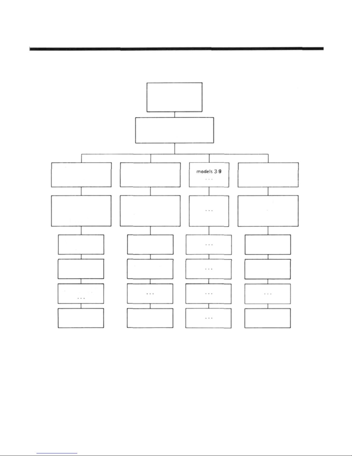
Startup Men u
Shows during
regular operation
System Menu
Settings that apply to all
models in storage
Manual Introductory Section
Model Menu 1
Settings for
Model #1
Condition Menus
Settings fo r all
conditions for
Model #1
Condition #1
Model #1
Condition #2
Model #1
conditions 3-7
Condition #8
Model #1
Model Menu 2
Settings for
Model #2
Condition Menus
Settings fo r all
conditions for
Model #2
Condition #1
Model #2
Condition #2
Model #2
Condition #8
Model #2
Model Menu 10
Settings for
Model #10
Condition Menus
Setting for all
conditions for
Model #10
Condition #1
Model #10
Condition #2
Model #10
Condition #8
Model #10
Manual Introductory Section, Page 5
Page 8

MANUAL LAYOUT
Manual Introductory Section
The instructions contained in this book are
written
in
great
detail
so
that
you may
understand the capabilities of your PCM 1024Z
system. We recommend that you spend some time
reading these instructions so that you can have a
good feel of what the system can do.
After this introduction are some words about
safety and proper operation of your Futaba
system. Next is a section on general operational
principles, including adjustments that you can
make on the transmitter to make it 'fit'your flying
style.
Next are instructions for system-level programming. This system-level programming is important
because it is used with a ll three types of models
that the PCM 1024Z system can be set up for. This
includes model menu selection, system voltmeter
operation, tachometer usage, servo bar graph display, trainer setup, and model data transmission
and copying.
A section on general model settings follows.
This section covers the topics of model setup that
are common to all model types, such as setting
throws, servo reversing, type selection, model naming, and others. The remainder of the menus are
specific to the particular type of model.
After the general section is a list of the common
condition menus that apply to all three types of
aircraft that the 1024A system can accommodate.
This is followed by three sections which describe
the setup procedures for aircraft, helicopters, and
sailplanes. At the beginning of each model setup
section is an example setup procedure that describes all the steps needed to set up all the desired
flight conditions for a model. Each of these section s assume that you are familiar with the general
system-level operations sections.
easily
The rear of the manual contains blank data
tables that may be used to record the data that
you have programmed into your system, and contains technical details of this system. Be sure to
make a photocopy of the blank data tables before
you write in them.
We hope that you find the PCM 1024Z System
Manual very hopeful. Please feel free to write to
Futaba if you feel that any corrections or clarifications should be made.
Manual Introductory Section, Page 6
Page 9
FLYING SAFETY
Manual Introductory Section
Safety is very important when you are flying
radio-controlled models. If you fail to follow the
installation, setup, and operation instructions in
this manual, or if you ignore warnings or rules set
by others, you may cause the partial or total destruction of your radio control system, aircraft,
and endanger yourself or other persons or property.
You
are
responsible
model, and may be held liable for any damages
your activities cause.
for
safe
operation of
your
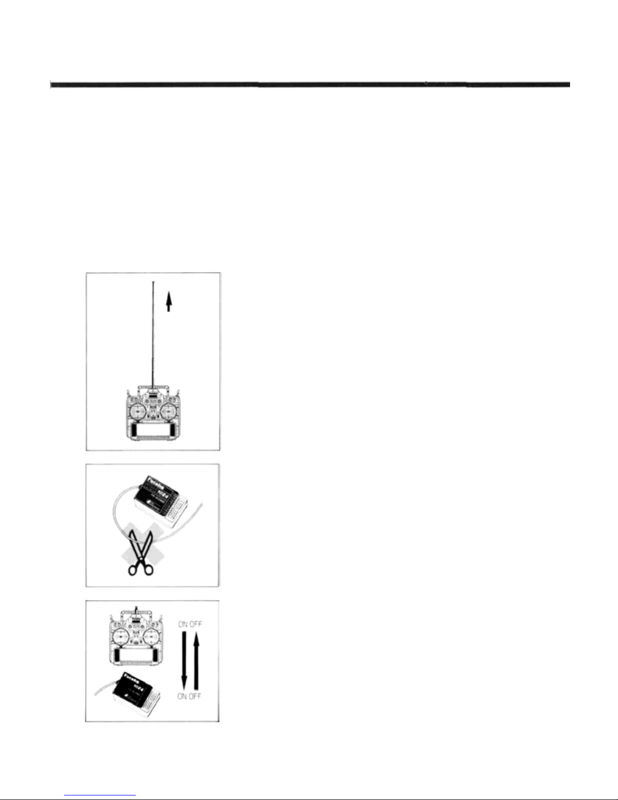
Before flying, carry out a range check on the ground with the
transmitter antenna extended only one step. Note th e distance you
can achieve without loss of control — it should be at least 30 paces.
We recommend a range check before each flying session to verify
that your system is working properly.
When flying, be sure the antenna is fully extended. If the antenna
is not fully extended, your model's effective range is reduced, and
interference can cause difficulties even at short range.
Please maintain your system properly. Install it
in your aircraft using the proper procedures,
inspect the model frequently for correct operation
and structural and control authority, and be certain tha t you a re capable of handling the model in
unusual situations. Do not fly over or near spectators or where your model could injure any person
or property. Do not fl y unless you are sure of your
flying skills, radio installation, and model integrity.
Please
ask
for
assistance
if you are not sure about your qualifications.
from
an
experienced
pilot
Be sure that you do not shorten the receiver antenna, either by
cutting
some
off,
or by coiling the
length trail behind or below the aircraft. Cutting the antenna will
reduce the effective range of the system and increase the chance of
interference.
When turning on your radio system, first turn on the transmitter,
then turn on the receiver. When turning off the power, turn off the
receiver first, then the transmitter. If these turn-on sequences are per-
formed in reverse order, the receiver may pick up spurious signals and
cause the servos to drive hard over, causing possible damage to the
radio system and the control linkages.
Manual Introductory Section, Page 7
excess
up.
Instead,
let the
excess
Page 10
Recharge
Manual Introductory Section
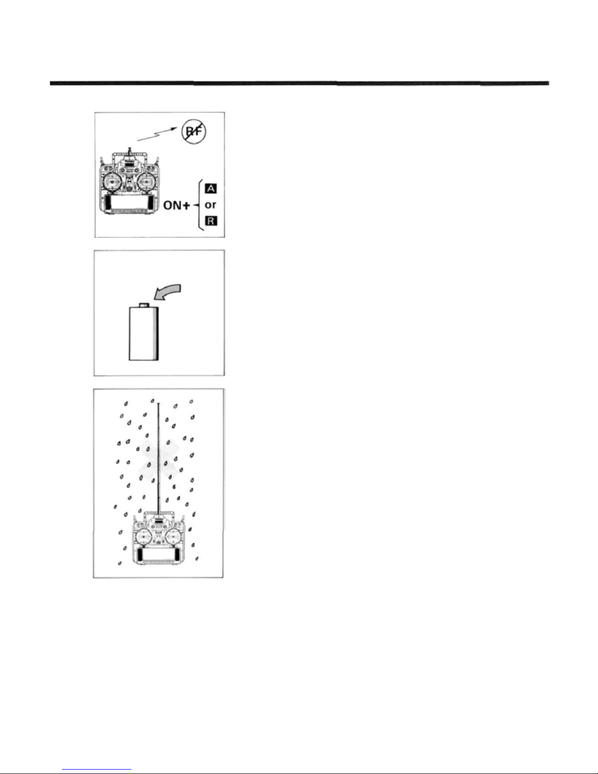
If you are using the Synthesized transmitter module FP-TK-FSS,
be sure that you know the transmitting frequency before switching
on. If yo u don't know the frequency, hold the [A] or [R] key down
as you switch on power. The transmitting frequency will be displayed
but radio transmission is deactivated. Once you h ave determined the
frequency,
secure
the appropriate frequency
control
device
and
turn
on power to operate normally.
Be sure to charge the transmitter and receiver batteries fully. If the
system has not been used for a long time, be sure to charge at least
24 hours before using the system, and check both batteries with the
system voltmeter at high load (500 mA). The transmitter battery
should remain above 9.4 volts, and the receiver should be above 4.7
volts. IF EITHER BATTERY INDICATES LOWER THAN THIS, DO
NOT FLY. Recharge the batteries first.
Do not quick charge the battery. Overcharging the battery will
cause the battery to overheat and creates a ver y dangerous situation.
Do not expose your system to rain or allow water to get inside the
case. If water does penetrate the case, control of the model could be
lost, resulting in a crash and danger to others. Use a waterproof cover
or wait until the conditions are dry before attempting to fly.
Manual Introductory Section, Page 8
Page 11

Manual Introductory Section
PCM 1024Z
• The optional CAMPac memory module stores up
to 10 model setups, and may be exchanged between different PCM 1024Z transmitters so that
model data may be rapidly transferred, or
backed up.
• The telescoping antenna is stored within the
transmitter, but when it is extended, it may be
easily rotated in any direction using the spherical
joint
on the
• Flight
• Switch Function Position Modification function
• The Type Selection Function allows any PCM
•
Condition Switching
trims, and other data to be matched to existing
flight conditions immediately upon movement
of a user-defined switch. A programmable Delay
circuit
makes
conditions. Each flight condition may have independent values for trims, mixing authorities,
and presets.
allows the owner to set the p o si ti o n and function
of all sticks, knobs, sliders, and switches as he
desires.
1024Z transmitter to be used for airplanes, helicopters, or sailplanes. The model type may be
selected from a menu screen.
Exclusive
changes
for each model in memory, and prevents unintentional trim changes. Trim functions may be
assigned to any stick or control.
Digital
easy
NOTABLE SYSTEM FEATURES
top
of
the
smooth
to
do,
transmitter
transitions
Trim
remembers the
case.
allows preset mixing,
between
function
makes
trim
flight
trim
status
• Large Liquid Crystal Display and Soft Keys
make model programming and data input easy.
Inputs change memory instantly, so immediate
verification of inputs is possible.
• The optional Frequency Synthesized Receiver
(R309DPS) allows rapid frequency changes to
eliminate frequency conflicts on crowded flying
fields.
• Programmable Trainer Function allows the
instructor to choose which functions are used
for training, and a special feature allows simple
correction by the instructor without disconnecting the student.
• Detachable Transmitter Battery Pack may be
easily removed from the transmitter and charged
separately, or used as an independent spare.
These are fust a few of the outstanding PCM
1024Z features. You can read about many more of
the features
never know what you've missed !
in
the manual.
Please
do
so — or
you'll
Manual Introductory Section, Page 9
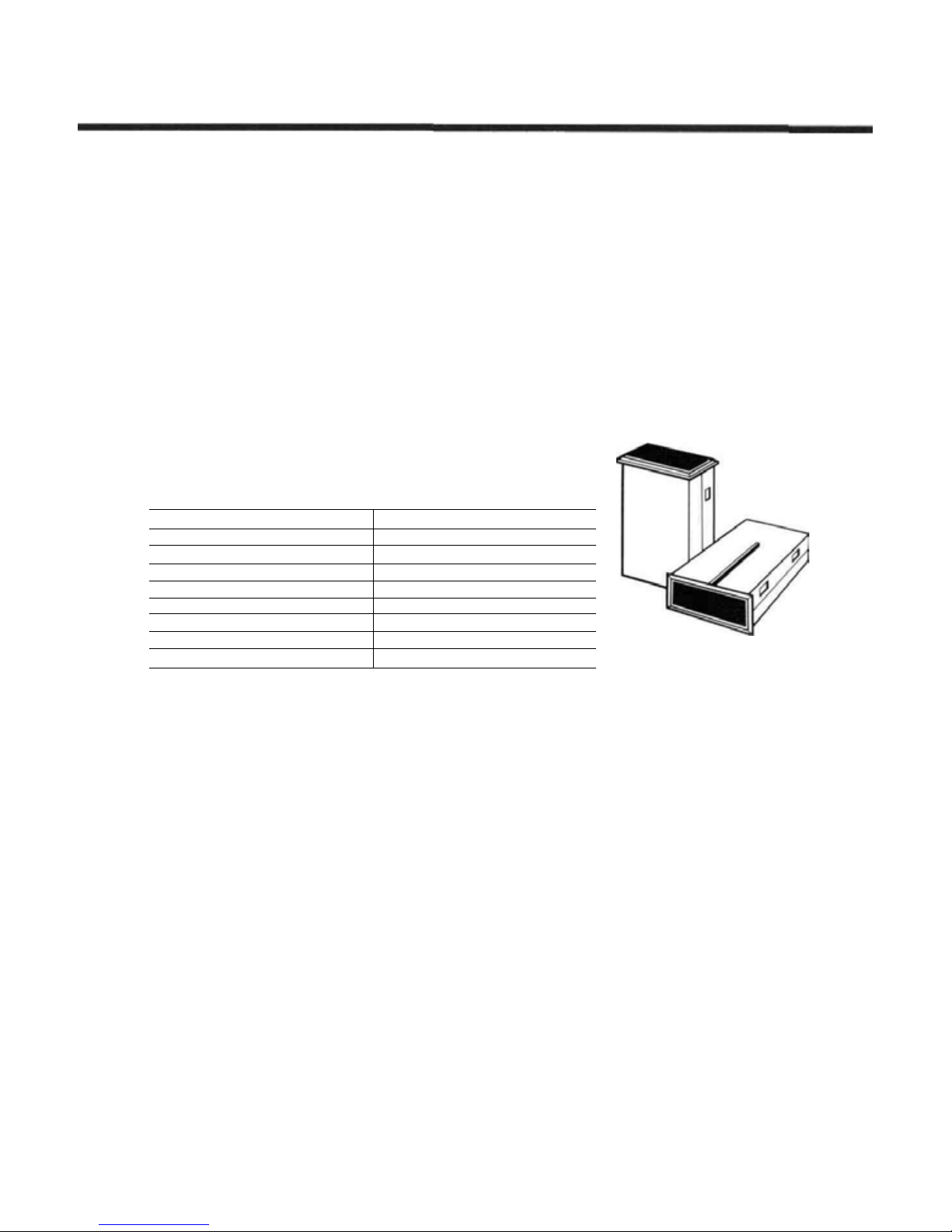
Page 12

Manual Introductory Section
PCM 1024Z
SYSTEM CONTENTS
Manual Introductory Section, Page 10
Page 13
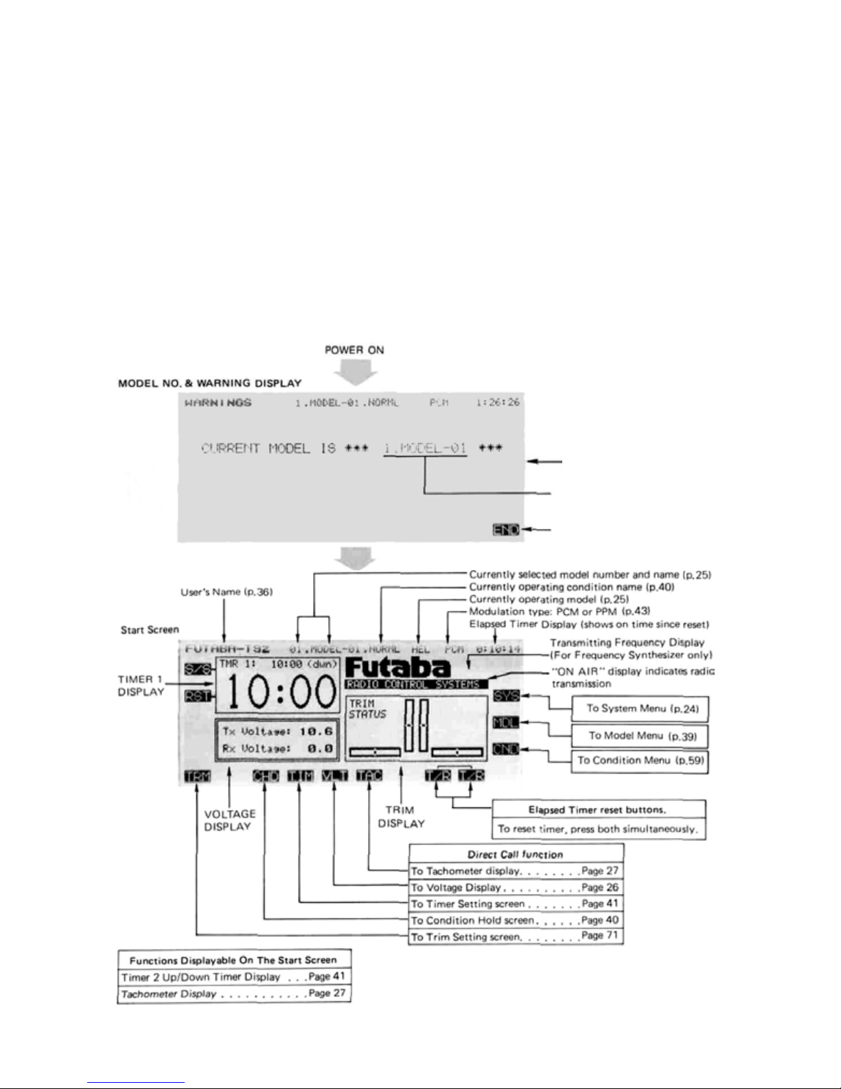
POWER ON SCREEN DISPLAYS
Manual Introductory Section
After the transmitter's power switch is turned
on, the current model number and name is displayed (see next page for what happens on the
initial turn-on). Check to verify it is the desired
model, otherwise you will have to change it in the
System menu. There may also be a caution message displayed for any special mix functions and/
or non-default flight condition switches that are
turned on. This caution message will be accompanied by a warning sound of six beeps repeated
every two seconds, and will continue until the offending switch is deactivated. You may hit the END
key, or wait a few moments to display the starting
screen.
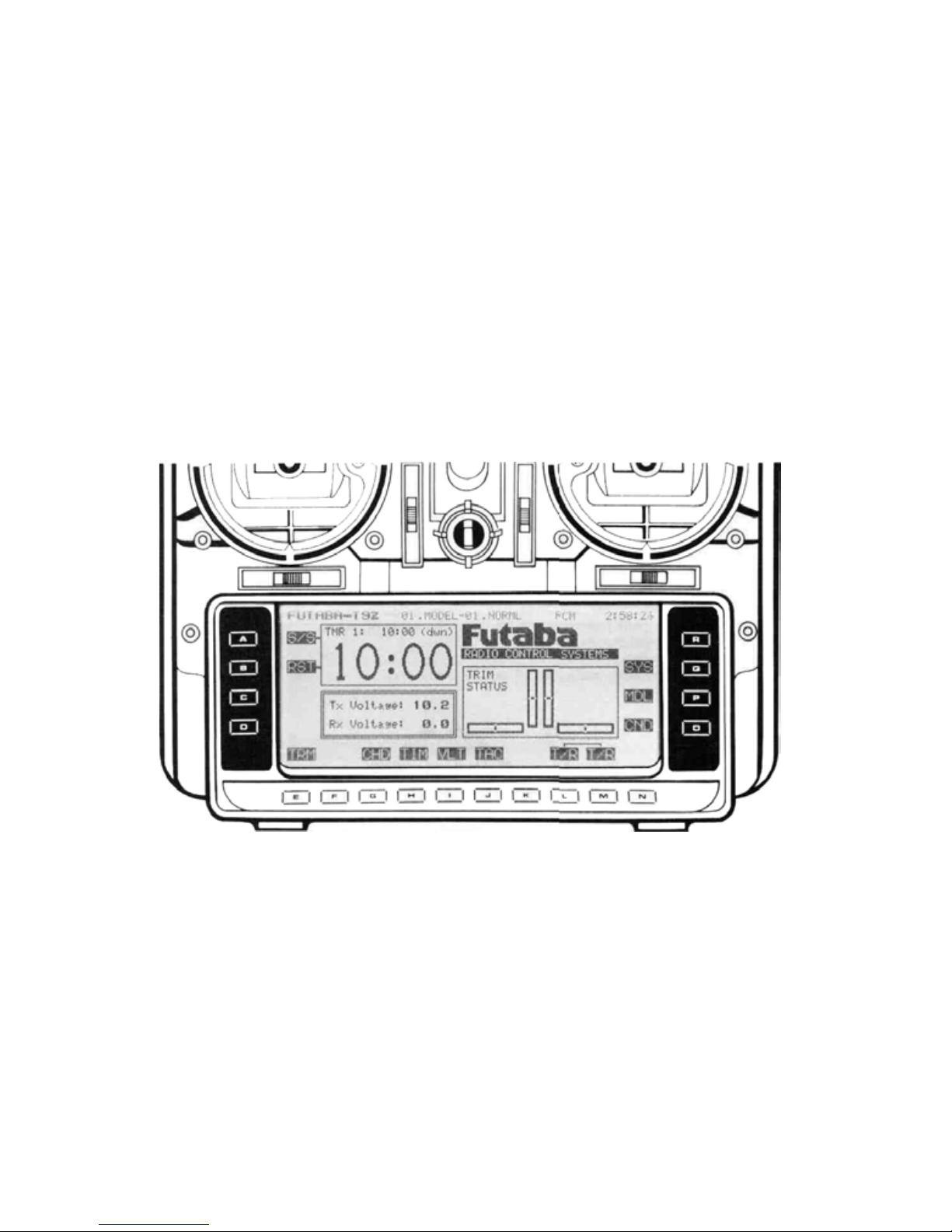
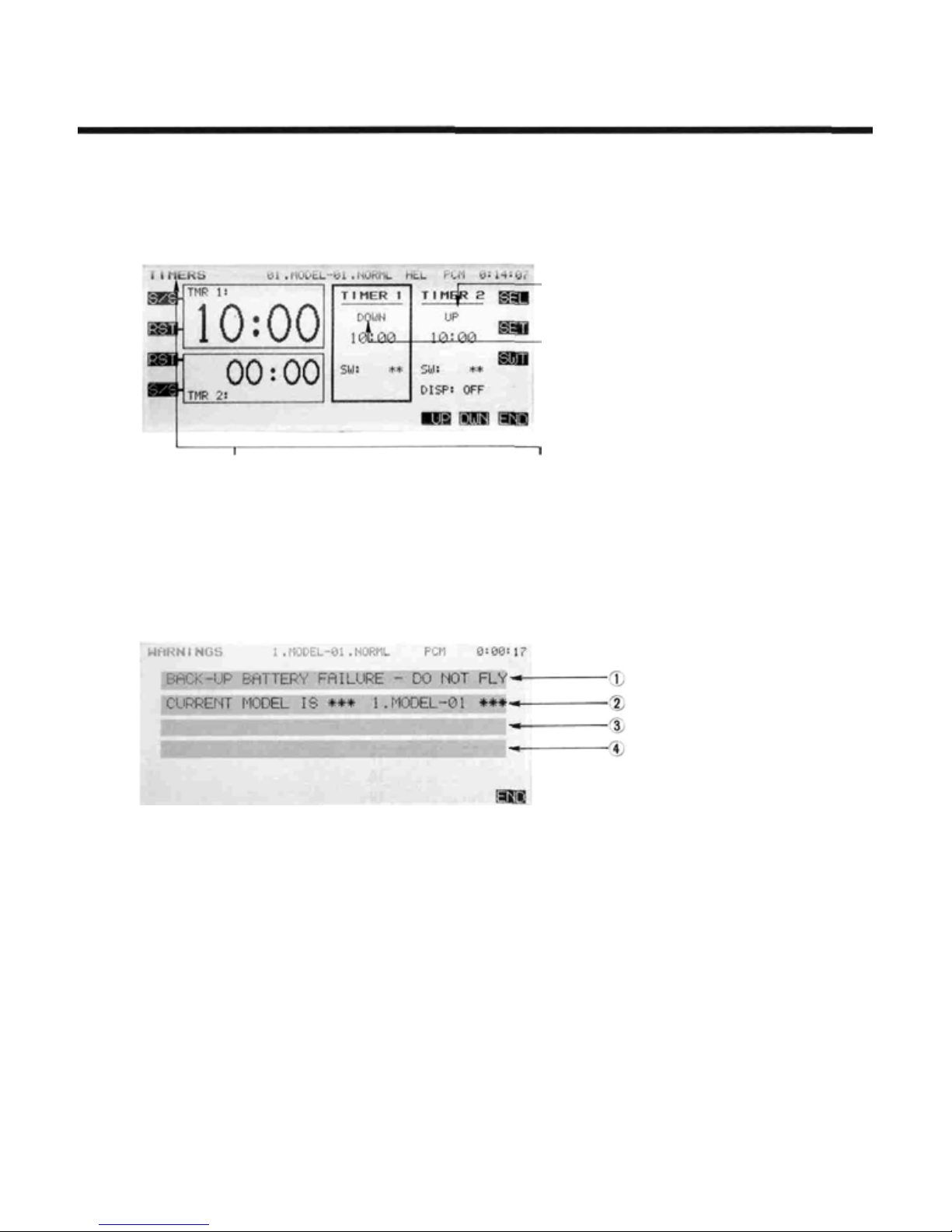
The Home screen displays the user's name, the
active model memory and flight condition, the
Timer #1 display, the system voltages, and the
trim
status. The
menus are also displayed. To switch to these dif-
ferent screens, press the desired key A to R .
BE SURE TO CHECK THE MODEL NAME AND
CONDITION BEFORE FLIGHT. One of the most
common
model setup loaded in the transmitter.
crash
selection
causes
keys
is
taking
• Displayed for several seconds
- Currently selected model
number and name
• Immediate switch to
start screen
off
to
with
the
the
various
wrong
Manual Introductory Section, Page 11
Page 14
WORKING WITH TH E CAMPAC MEMORY MODULE
Manual Introductory Section
The optional CAMPac Memory Module can be
used to store model setup data separately from the
transmitter. Its advanced electronic design needs
no battery back-up power, so the CAMPac may be
used to transfer data directly into another PCM
1024Z system.
When the transmitter power switch is turned on
for the first time after the set is purchased, or
when the power switch is turned on after the
memory module has been changed, the "INITIALIZE EXT MEM?" message will appear at the
center of the screen. Press the YES key to initialize the memory module so it is ready to store
data.
Number of fl i gh t conditions
1
2
3
4
5
6
7
8
Memorizable model data
16
The CAMPac can store and memorize as many
as 16 s et s of model data, depending on the number
of flight conditions. When used in conjunction
with the transmitter's 10-model memory, as many
as 26 different model setups may be permanently
stored. The table below gives the numbers of
model data that the CAMPac can store, which
depends on the number of flight conditions. When
power is turned on, it may ta ke some time to copy
complicated model and flight condition data into
the transmitter's memory. This normally takes just
two or three seconds.
9
6
5
4
3
3
2
Moving the CAMPac from one PCM 1024Z
transmitter to another is one way of transferring
model setups from the f irs t to the second. Another
Manual Introductory Section, Page 12
way may be used with transmitters that do not
have the CAMPac installed. This method requires
an optional data transfer cord.
Page 15
USING THE SOFT KEYS
The soft keys are used to call up the different
menus during operation and programming. For
example, to call up the System Menu from the
home screen shown above, press the Q key (next
to the SYS label). Press the A to R keys that
correspond with the function names to get to that
particular function. Whenever a key is pressed, you
will
hear a confirmation
beep.
Manual Introductory Section
Manual Introductory Section, Page 13
Page 16
OPERATION WITHOUT RADIO TRAMSMISSION
Manual Introductory Section
If you'd like to make some small corrections to
a setup OR find out what frequency the Synthesizer module is set for without radiating AND
without removing the transmitter RF module or
using the DSC cable, you can do this by turning on
the power switch while simultaneously holding the
A or R keys. This may also be used to find out
what frequency the synthesizer transmitter module
will
way, check to be sure that the "ON AIR" display
is not on. You can now set the data or check what-
ever you need to. When you are done, you may
reset the transmitter by turning off the power
switch. The transmitter will radiate normally on
the next turn-on.
SYSTEM MONITOR LIGHTS & WARNINGS
There are two indicator lights above the power
switch on either side. The right-hand light flashes
when the transmitter is transmitting, or if a flight
condition or mixing switch is activated. The lefthand indicator lights when the system power is on,
and blinks during automatic data tra nsfe r.
In the airplane mode, either the Snap Roll
[SNP] or the Airbrake [ABK] switches will light
the indicator lights. For helicopters, Throttle Hold
[HLD] or Inverted switches [INV] will cause
flashing.
activate the light.
In
sailplanes,
Butterfly
mixing
[BFY]
will
every four seconds when Condition Hold [CHD] is
operating to remind you to turn it off. For your
convenience, the left and right sliders on the sides
of the transmitters emit a beep whenever they are
set at their center positions. This feature allows
you to center them without having to take your
eyes off of the model.
be using. When
You should also be aware that a beep sounds
you
power
up
the
system
this
CAUTION!
If you are using the Synthesized transmitter module FP-TK-FSS, be sure that you
know the transmitting frequency before
switching on. If you don't know the frequency, hold the A or R key down as you
switch on power. The transmitting frequency
will be displayed but radio transmission is
deactivated. Once you have determined the
frequency, secure the appropriate frequency
control device and turn on power to operate
normally.
Manual Introductory Section, Page 14
Page 17
SYSTEM STATUS AND ALARM DISPLAYS
The PCM 1024Z System provides you with a
number of indicators and displays to show you
that your system is operating corr ectly. This sec-
tion will explain each display's function
Manual Introductory Section
ON AIR display and beep
This display is turned on when radio waves are
being transmitted.
Enter ID No. display
This display indicates when the security mode
is set. In this case, model data cannot be
changed. See the section on data protection to
reset this display.
EXT MEM ER R display
This display blinks when a data error occurred
during transmission of data between the transmitter memory and the memory module. Turn
off the power. DO NOT REMOVE OR INSERT
THE MEMORY MODULE WITH THE POWER
TURNED ON. THIS ACTION COULD DESTROY THE MODULE.
(D BACK-UP BATTERY FAILURE - DO NOT FLY
This warning is displayed when the data stored has been
lost for some reason. A beep wi ll sound simultaneously.
When the power sw itch is turned on again, the error display goes off and the data returns to the factory default
state. The lithium data backup battery needs to be replaced, or there is a fault in the system. Return the
system to the Futaba service center for assistance. The
life of the lithium battery varies, but is usually at least
five years.
2 CURRENT MODEL I S* ** ##.NAME ***
This display shows the model number and model name
currently stored in the active area of the transmitter. It
will disappear a few seconds after the system is turned on.
DATA PAC IS MISSING - LOADED MODEL1
This message is displayed whenever the transmitter is
turned on with the memory module removed and the
active model data was stored on the module. Without the
desired model data, the system loads the Model 1 data
instead.
Manual Introductory Section, Page 15
LOW BATTERY display and beep
This display and warning beep are to notify the operator
that the transmitter battery is low.
TO PREVENT PROBLEMS, LAND THE MODEL
AS SOON AS POSSIBLE.
PLL ERROR and beep
This display blinks and sounds when the synthesized
frequency module is removed during operation.
Be sure to turn off power before installing the module.
Do not remove or insert the module with power on.
3 CAUTION: NON-DEFAULT COND IS ACTIVE
This warning message is displayed, and a beep sounds,
whenever the transmitter is turned on with a flight condition switch activated. This display and alarm will turn
off as soon as the fl ight condition switch is turned off.
4 CAUTION: SPECIAL MIX FNCT IS ACTIVE
This message and alarm a re activated when the transmitter
is turned on with a mixing switch activated. The alarm
monitor above the power switch also blinks. All of these
wil l stop as soon as the mix switch is changed to i ts OFF
position.
CAUTION: ENGINE CUT FNCT IS ACTIVE
If the power is turned on with the engine cut switch on,
this message is displayed and a beep sounds. When the
engine cut switch is turned off, the display and alarm
stop.
Page 18

USING YOUR FUTABA SYSTEM
This section contains information on charging the batteries in your
system, and installing the airborne components in your model. We will
also tell you all the ways that you may customize your PCM 1024Z
System mechanically, so it "feels right" in your hands.
Then, we will show you all the features that are used by all the
model types that may be controlled by the PCM 1024Z system. This
will include all the exclusive PCM 1024Z features, including timers,
trim settings, voltmeter with load, direct-servo connect, and trainer
systems.
Manual Introductory Section
Using Your Futaba System: Contents
Installation
Radio
Charging & Direct Servo Connect Operation .............. 18
Stick Length Adjustment ........................... 19
Stick Tension Adjustment .......................... 19
Stick
angle
Antenna Angle Adjustment
Rubber Protective Pad Installation ..................... 21
Transmitter Battery
Transmitter
Optional Synthesized Frequency Module & Receiver
(see caution message) ............................. 22
Flight
Condition
................................
adjustment
RF
.............................
.........................
Replacement
Module
Switching
............................
.....................
..........................
17
20
20
21
22
23
Manual Introductory Section, Page 16
Page 19

RADIO INSTALLATION
Manual Introductory Section
Please observe the following precautions during
the installation of the radio into your model and
subsequent flying activities:
Servo Installation
Mount each servo snugly to a sturdy plywood
servo tray or use the provided mounting trays. Use
the supplied rubber grommets on the mounting
ears, and tighten the screws to hold things snugly
but try not to crush the grommets completely.
If you squeeze them too much, their vibration
dampening characteristics will be reduced.
Receiver connections
Connect the receiver, servos, switch, battery,
and gyro (if used) in accordance with the model
setup directions given in the appropriate model
sections. For aircraft, see page 80. For helicopters,
refer to page 104. For sailplanes and electrics, use
page 130.
Receiver Installation
Wrap the receiver in cushioning foam rubber,
and place it in a sealed plastic bag to prevent it
from fuel leaks or inadvertent water landings. Use
rubber bands wrapped around the receiver to
provide strain relief for the antenna, switch, and
servo wiring. Secure with foam pieces on all sides.
Run the antenna down the inside of the fuselage, or secure it to the top of the vertical fin
with a small
antenna wire, or tie it into a bundle. Reduced
range could result. If you experience problems
with an internal antenna, tr y routing it differently,
or move it outside of the model fuselage.
Switch Harness Installation
When you install the switch harness, be sure
that the rectangular hole is slightly longer than the
full switch stroke, so that it moves smoothly from
On to Off and vice versa. Try to install the switch
on the opposite side from the engine exhaust, and
away
from
rubber
dust
or
band.
dirt.
Do
not
shorten
excess
Now, connect each servo with its pushrod.
Again move each transmitter control in succession,
verifying that control movement is the proper
direction. If a servo does not move in the proper
direction, use the reversing function [REV] in the
Model menu.
Servo Throw Adjustment
Operate each
check
that
no loose connections. If the servo does bind, the
current drain will be very high, and yo ur battery
will
not
last
crashing due to a low receiver battery.
Make sure that the servo can move its entire
throw amounts (including trim) without binding
anywhere. If necessary, use the Adjustable Throw
Volume [ATV] menu to reduce servo travel so it
does not bind.
Range Check
After installation is complete, perform a ground
range check by extending the transmitter antenna only
one step. With the receiver antenna full length, step
25-50 paces from the model. The servos should
operate normally at this distance. Continue walking
away until control is lost, and note the approximate
distance. This is your ground range, and should be
repeated before each flying session.
Electrical Noise
Electrical noise is created by the touching of
two
metal parts, and
that heard on an AM radio during a thunderstorm.
Your Futaba radio set is resistant to electrical
noise, but no set may be made completely immune. For best flying range, avoid metal-to-metal
contact wherever possible.
the
for
control
servos
much
over
don't
time.
creates
bind
This
its
and
"static"
full
travel,
that
there
exposes a risk
similar
and
are
of
to
System and Servo Operation Check
Turn on the transmitter power first, then the
receiver power. Be sure that the transmitter anten-
is
fully
na
neutral positions. Operate the transmitter sticks,
knobs, and levers individually and be sure that the
appropriate servo follows the control movement.
If a servo does not move as it should, first check to
see that it is plugged into the correct receiver output. If it is not, move it to the correct output. If it
is in the correct location, verify that you have
activated the appropriate mixing functions.
extended.
All
servos
will
travel
to
their
Manual Introductory Section, Page 17
Page 20
CHARGING & DIRECT SERVO CONNECT OPERATION
Manual Introductory Section
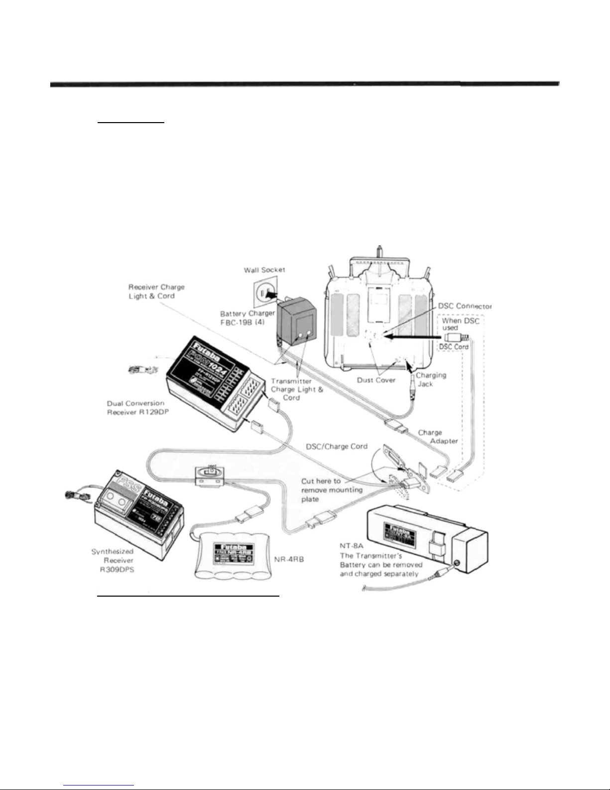
Battery Charging
Your Futaba FP-9ZAP and -9ZAH system is
equipped with rechargeable Nickel-Cadmium batteries. The figure shows the necessary connections
for charging the transmitter and receiver battery
packs. Both packs may be charged at the same
time or they may be charged individually. The
charging connections bypass the power switches,
so the set will not operate ev en if switched on.
The minimum recommended charge time for a
spent battery is 15 hours, but it will not damage
the batteries to charge them longer. However, if
the battery has not been used for some time, it
may take several charge/discharge cycles before
the battery resumes its full-capacity flight duration.
When fully charged, the system will provide
approximately 60-80 minutes of flying time,
providing there is no stalling of the servos. Be sure
to check the state of the receiver battery frequently with the built-in voltmeter function [VLT] in
the System menu. If the receiver battery drops
below 4.4 volt s under load, do not attempt to fly.
Direct Servo Connect (DSC) Cord Connection
Using the DSC system, you may directly con-
nect the transmitter
to
the
receiver
to transmit radio waves. This feature can be extremely useful for adjusting any settings on the
model
ance.
Additionally,
without
worrying
with
about
the
cord may be used to measure the receiver battery
voltage (for this display, see
menu).
When you wish to use the DSC system, you will
need to install the accessory DSC/Charge Cord
into
the
side
of
the
model fuselage (t his
without
frequency
receiver
VLT
in the System
also be used for
DSC
having
cable into the receiver jack, then plug the
round DIN connector into the back of the transmitter. Switch
transmitter.
To
check the receiver battery voltage, switch
off,
clear-
the
DSC
off the receiver and move to the VLT menu in the
System area. You may apply different current
loads
to
assess
tery. When you are through with DSC and/or
Receiver battery monitoring, remove the DIN
cord
may
Manual Introductory Section, Page 18
connector from the rear of the transmitter.
charging). To operate,
plug the
on the receiver ONLY — not the
the
condition
of the
receiver
bat-
Page 21
STICK LENGTH ADJUSTMENT
Manual Introductory Section
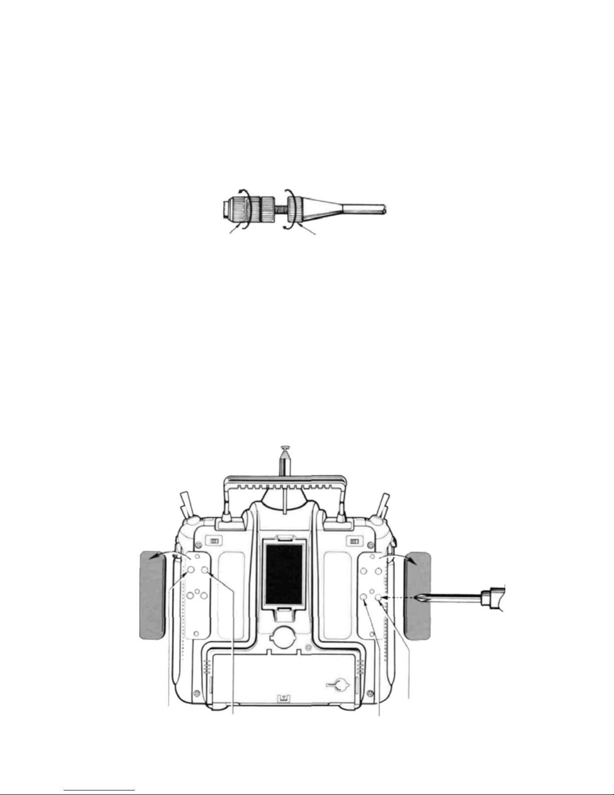
The sticks on your PCM 1024Z System feature
non-slip ends, and the length may be adjusted to
be most comfortable for the pilot. To change stick
length, unlock the stick tip by turning counter-
Non-Slip Stick Tip
STICK TENSION ADJUSTMENT
You may easily adjust the tension in the PCM
1024Z sticks to suit your personal preferences. To
adjust, you
ment screws in the back of the tr an smitter.
Gently pull up on the rubber grip and remove it
from the rear of the transmitter. Then, use a small
will
need
to
get
access
to
the
adjust-
clockwise. Move the tip to the desired position,
and then lock to length by moving the locking
piece upwards counterclockwise.
Locking piece
cross-point screwdriver to change the length of the
springs which tightens or loosens them. Be careful
not to push too hard, as it is possible to damage
the inside of the transmitter. Always turn off
transmitter power before adjusting stick tension.
Elevator
(Mode 1)
Elevator (Model)
Aileron Rudder
Manual Introductory Section, Page 19
Page 22
STICK ANGLE ADJUSTMENT
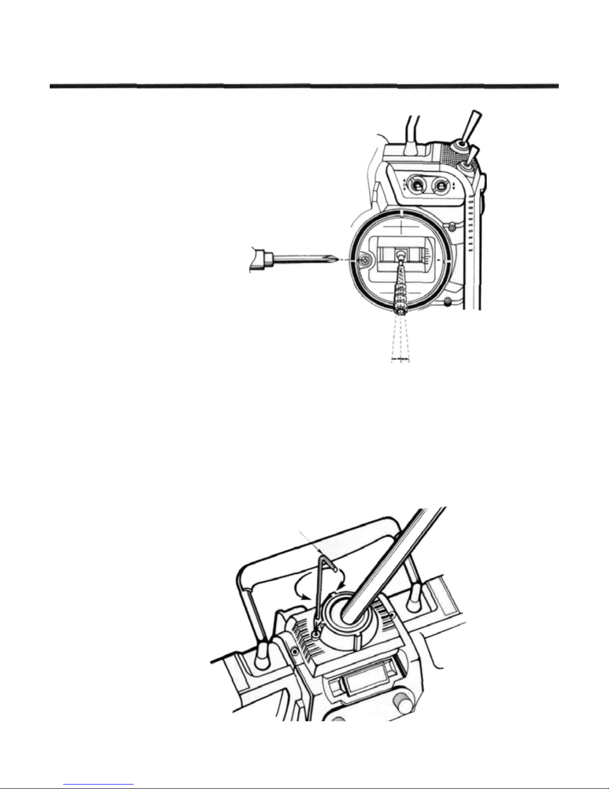
For the comfort of the operator, the angle of
the open gimbal s tic ks may be adjusted f ro m 3 to
the inside to 4.5° to the outside of the transmitter
case. This angle is adjusted by rotating the adjustable screw as shown in the figure. Simply turn
adjusting screw to change the s tic k angle in or out.
Manual Introductory Section
ANTENNA ANGLE ADJUSTMENT
Your PCM 1024Z system features an antenna
that may easily be pivoted to a direction that you
like. Simply move it to the desired pointing angle.
Before collapsing the base of the antenna into the
transmitter, return it to the straight-up position. If
Use the supplied hexagon wrench to adjust the
resistance to movement. Clockwise tightens,
counterclockwise loosens.
the antenna is til t e d, it will not fit into its housing.
The force required to pivot the antenna may be
easily adjusted. If the antenna movement is too
tight,
collapsing
into
the
case
will
be
difficult.
Manual Introductory Section, Page 20
Page 23
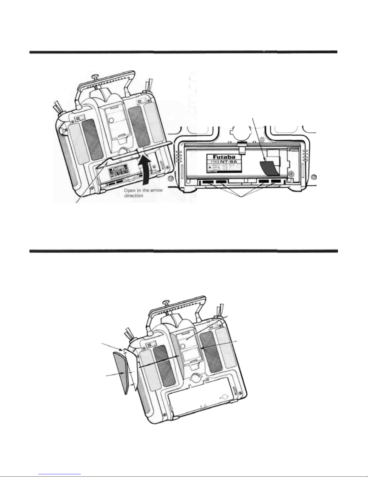
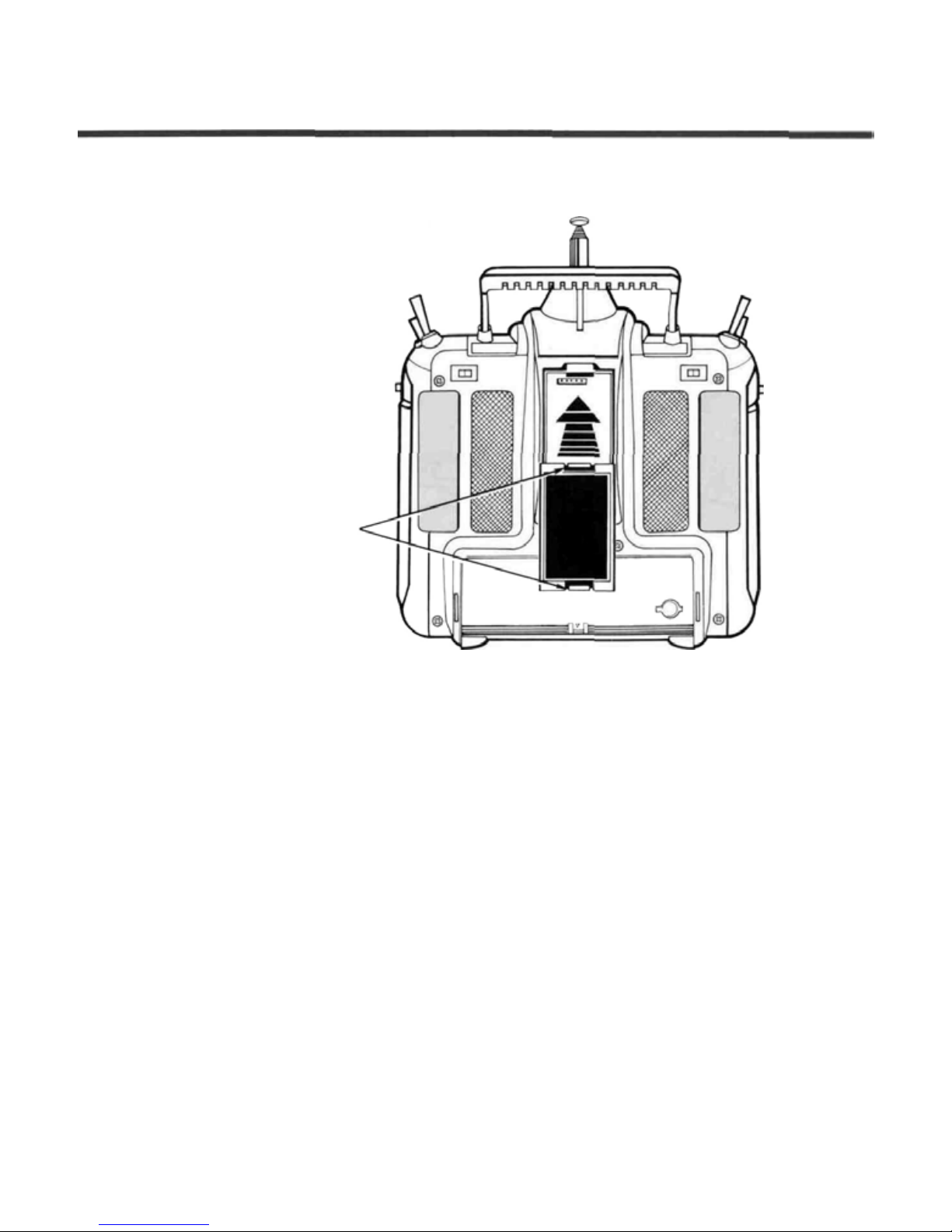
TRANSMITTER BATTERY REPLACEMENT
Battery Cover
Manual Introductory Section
The transmitter battery is easily removed and
replaced, making it simple to have a spare battery
pack for extended flying duration.
Open the battery cover and remove the rechargeable battery pack by pulling outward on the
ribbon. Be careful not to damage the battery cover
or drop the battery pack.
RUBBER PROTECTIVE PAD INSTALLATION
We recommend that rubber protection pads be
installed in case the transmitter is ever rested on its
back.
Double-sided tape
Stick the do ubl e-si ded
tape to t he inside of the
protection pad
RF Module
Repeat for other side.
Stick the protection pads to the
shaded area of the transmitter.
Manual Introductory Section, Page 21
Page 24
TRANSMITTER RF MODULE
The PCM 1024Z transmitter is designed to work
with either the FP-TK-FM or the FP-TK-FSS frequency-synthesized Radio Frequency (RF) mod-
ules. Other modules may not be used.
It is normal for the module's temperature to
rise during operation.
To remove the module, press
inwards on the top and bottom
tabs and simultaneously pull the
module away from the rear of the
transmitter.
Manual Introductory Section
OPTIONAL
The R309DPS synthesized-frequency receiver
and matching transmitter frequency module are
supplied with the PCM1024ZAPS and PCM
1024ZHPS systems. The transmitting and receiving
frequency may be easily changed without removing any crystals or exchanging frequency modules.
The ability to rapidly change frequency is a great
advantage on a crowded flying field or in contest
entry.
The receiver will also work with any other
Futaba 1024 systems. For more information on
the synthesized system, refer to page 37.
SYNTHESIZED FREQUENCY
Manual Introductory Section, Page 22
MODULE
CAUTION
If you are using the Synthesized transmitter module FP-TK-FSS, be sure that you
know the transmitting frequency before
switching on. If you don't know the frequency, hold the A or R key down as you
switch on power. The transmitting frequency
will be displayed but radio transmission is deactivated. Once you have determined the fre-
quency, secure the appropriate frequency
control device and turn on power to operate
normally.
&
RECEIVER
Page 25

FLIGHT CONDITION SWITCHING
Manual Introductory Section
Flight control switching is among the most
powerful features available in your PCM 1024Z
system. It is a function that allows you to change
virtually all the models' trims, mix settings, and
responses with the flick of a switch — while your
model is airborne! You can think of this as a
means of switching between as many as eight dif-
ferent model setups as you desire.
All the mixing and deflection angles can be
changed during flight condition switching. You
may pick and choose those settings that result in
the best flight characteristics for your model, and
leave the rest alone.
As an example, you may set up different condi-
tions corresponding to varying crosswind situations, or you can have different response "feels",
like a reduced control authority for smoother
landings. You may call up an entire group of
settings for a snap roll on a single switch. Helicopters may be set up for best response for aerobatics
and autorotation. Sailplanes may have settings
matched to the very different flight conditions for
launching, normal cruise, speed, distance, and
landing.
You may think of the different condition set-
tings as sheets of paper in a folder, and the trans-
mitter as an envelope with a clear window. As you
select each flight condition, you see its parameters
through the window, and not those of the others.
Each "sheet" can have completely different settings on it.
Manual Introductory Section, Page 23
Page 26

System Section
SYSTEM
The following controls and menus are used for system-wide settings.
These are settings that are stored fo r, or may be used for any and all
of the different model setups stored in the PCM 1024Z's memory.
To select any of these keys, first select the horizontal line contain-
ing the item you wish to select, using the B or C keys adjacent to
the
left-hand
F to L keys underneath the display.
Select Line With
These Keys
MENU
side
of
the
screen.
Then,
select
the
desired
Function Selection Keys
item
with
the
To Home Screen
To Model Menu
To Condition Menu
Listed below are the contents of the System Settings Menu:
System Menu Contents
Item_______Definition____________
MSL . .
VLT. . .
TAC.
SRV . .
TRN . .
DTN . . .Data Transfer Function . . . .Copies model data to another.... 30
CPM . . .Copy Model Function . . . . .Copies a setup into a second. .... 31
CPC. . . .Copy Condition Function . . .Copies a single condition to ..... 32
PAR.
UNA . . .User Name Registration . . . .Set up your name & security . . . . 34
FRQ . . .Transmitter Frequency. . . . .1024ZAPS/HPS Synthesized .... 35
Setting The Frequency Synthesizer. . . .Choosing the desired frequency . . . 36
Receiver
SWT
.Model
Selection
.Voltmeter
. .
.Tachometer
.Servo
Test & Bar
Graph Display and cycles
.Trainer System
. .
.Parameters.
Setting systems only (See C AUT IO N
. .
.Switch
Setting.
........
...........
..........
.......
........
..........
........
.Sets
.Use
Function
.Use
to
load desired model's
settings
.Use
adjustable load
check batteries
.Measures
speed
.Displays
channels
1024Z
memory
another
.Sets
Contrast
code
message)
activate functions
propeller
servo
desired
instructional.
Auto-Off and
to
define switch
Page
.....
to
........
rotational
positions
Screen
to.
....
.......
......
......
.......
25
26
27
28
29
33
37
System Section, Page 24
Page 27

MS L—MODEL SELECTION
System Section
This function is used to load the settings of the
desired model into the PCM 1024Z's memory. The
settings may be selected from either the transmitter's built-in memories, or from an optional
CAMPac. Remember that up to 10 memories are
Transmitter Model Memory List
Model Memory Selection Keys
To load a desi red model from internal transmitter
memory to the active area:
1. Select the desired model number with the A to J
( 1 to 1 0 ) keys
2. Press the L ( YES ) key if correct, otherwise use the
M ( NO ) key to start over. Verify that the chosen
model number and name is now shown in the display's
top center.
3. Finish by pressing the N ( END ) key.
To load a desired model from CAMPac memory
module to the active area:
1. Press the P (
models in the memory module's contents. Press it
again to get the remaining models. To return to the
previous model list, press (
desired model number with the
21 t o 26 ) keys.
2. Press the L ( YES ) key if correct, otherwise use the
M ( NO ) key to start over. Verify that the chosen
model number and name is now shown in the display's
top center.
3. Finish by pressing the N ( END ) key.
NXT
) key to display the first ten
PRE
A
to J (11 to 20 or
). Select the
available in the transmitter, and as many as 16 may
be stored in the CAMPac. The CAMPac is not
loaded with default models initially; they must be
loaded with the Copy Model [CPM] function.
Active Model No. and Name
Selected Model
No. and Name
END returns to
System Menu
To DELETE a desired model from CAMPac memory module:
1. Press the P (
models in the memory module's contents. Press it
again to get the remaining models. To return to the
previous model list, press (
desired model number with the A to J ( 11 to 20 or
21to 26 ) keys.
2. Press the L (
R( DEL ) key to start over. Verify that the chosen
model number and name is now shown in the display's
top center.
3. Press the R (
4. If this is the correct model to delete, press the
L (
YES
(
NO) key.
5. Verify the deletion from the model list. Then, exit by
pressing the
NXT
) key to display the first ten
PRE
). Select the
YES
) key if correct, otherwise use the
DEL
) key.
) key. To choose another, press the M
N(END
) key.
System Section, Page 25
Page 28
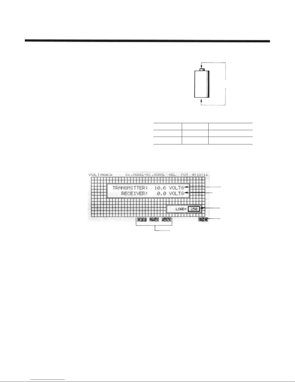
VLT—BATTERY VOLTAGE DISPLAY
This function may be used to check the voltage
of both the
a high-accuracy digital voltmeter, which continuously displays the measured results. The table
below indicates the measurement range of the
voltmeter.
The receiver battery may be tested with either
no load, or a load of 250 or 500 mA current flow.
Testing of the receiver battery requires a DSC cord
(the transmitter is always connected internally).
Be sure that the polarity of the receiver battery is
correct, or damage to the transmitter may result.
An alarm in the PCM 1024Z transmitter will go
off when the transmitter battery voltage becomes
too low. If you happen to be flying when this
alarm goes of f, be sure to land as soon as possible
before control is lost.
transmitter and
receiver
batteries
with
Item
No Load
Load (Choose)
Voltage Range
0-18V
3-
7V
System Section
Voltage Display
Remarks
OFF
Approx. 250 or 5 00 mA
To
switch loads on the receiver battery:
1. For no load, press the 0 (
2. For the 250 mA load, press the J ( 250 ) key
3. For the 500 mA load, press theK(
4. To leave the voltmeter function, press the
key.
Note: if you do not activate the second timer, the volt-
meter display appears on the regular screen.
OFF
) key
500
) key.
N ( END )
Transmitter Battery
Voltage Display
Receiver Battery
Voltage Display
Load Current
Setting
Return to System
Menu
• Receiver Load
Current Selection
System Section, Page 26
Page 29

TAC—TACHOMETER
System Section
The tachometer function in the PCM 1024Z
transmitter may be conveniently used to measure
the rotational speed of any propeller or rotor
blade, up to a maximum of 50,000 RPM. This is
very useful for testing engine performance, rotor
settings, etc. If you like, you may have the TAC
display always appear on the Home screen.
Activates TAC display
in Home screen
To choose the number o f blades on the propeller, use the
G to L ( 1 to 6 ) keys. To display the TAC display on
the Home screen, press the
toggles the display on or off. Use the N (
exit the TAC display.
Propeller Speed Measurement
1. BE VERY CAREFUL IN THE VICINITY OF THE
PROPELLER. KEEP YOUR HANDS AND ALL
EQUIPMENT AWAY FROM THE TURNING PROP.
E (DSP )
key. This key
END
) key to
Speed
RPM Display
Home Screen
Display Indicator
No. of Blades
Return to System
Menu
Keys to Select No. of Blades
2, Point the sensor, which is located in the left-hand side
of the PCM 1024Z transmitter, towards the propeller.
Read the measured rotational speed. You may have to
change the relative orientation to get a steady reading.
NOTE: Fluorescent lights in the vicinity of the
propeller can produce erroneous readings. If
you can't make your measurements outdoors, use an incandescent li ght or flashlight
to get a true reading.
System Section, Page 27
Page 30

SRV—SERVO CYCLE & BAR GRAPH DISPLAY
System Section
This key has two different functions: a servo
cycling mode, which slowly moves each servo to
its extreme positions, and a servo bar graph indication, which pictorially shows the position to
which each servo is being commanded. The servo
test function is useful for finding unevenness in
servos, and t h e bar graph function may be used fo r
roughly setting up models without using a receiver
or servos. This can be particularly handy in setting
up models with complicated mixing functions,
because the results of each stick, lever, knob,
switch input and delay circuit may b e immediately
seen.
The servo bar graph display is always operating
in this mode. To activate the servo cycling func-
tion,
first
turn
on the airborne
E (ON) key to start the servo cycling mode,
and use the F (OFF) key to stop the cycling.
When using the Bar Graph display to set up a
model or mix, be sure to verify that all controls
move the proper directions when actuated. Depending on servo orientation, it is possible that the
bar graph may indicate what appears to be the
correct directions of throw when one or more
servos actually need reversing.
Use the END key N to leave this function
and return to the System Menu.
system.
Press
the
Check Servos By Cycling
Check Functions and Mixing
Bar Graph Display
Return to
System Menu
Turn Servo Test On & Of f With These Keys
System Section, Page 28
Page 31

TRN—TRAINER SYSTEM
System Section
The Trainer function makes it possible for the
instructor pilot to choose which functions and
channels are to be used for instruction, making it
possible to match the training difficulty to the
student's skill level. A special function called Cor-
rection Control makes it possible for the instructor
to make corrections without overriding the student's inputs. Two transmitters must be connected
by an optional Trainer/Data Transfer cord, and the
Instructor transmitter should be programmed for
trainer operation, as described below.
Operation is simple: when the Instructor acti-
vates the trainer switch, the Student has control of
the aircraft (if the mixing mode is turned on, the
Instructor can make corrections while the student
has control). When the Instructor releases the
switch, control is regained. This is very useful
when the Student gets the aircraft into an undesirable situation.
The training system will work with any PCM
1024Z series transmitter. Futaba's 5U and 7U
series of transmitters may also be connected for a
student's usage. Note that in some cases a low
battery warning may appear on the 7U series, but
operation is unaffected by this warning.
- ACT/ INH Selection
Correction Mixing
Channel Selection
Instructor-Controlled
Channel Selection
ON/OFF Toggle
Switch Setting
Return to System
Menu
Channel Selection Keys
TRAINER MODE SETUP
To place the PCM 1024Z into the Trainer mode, press
the
TRN
key
sively toggles between ACTIVATE and INHIBIT, with the
from the System Menu. T he
current mode displayed just to the left of the k ey. Once
activated, the operation mode for each channel is selected.
PLACE THE STUDENT TRANSMITTER IN PPM PULSE
MODE. The instructor's transmitter may be in any transmission mode.
Controls and functions in both transmitters should be
matched. With two PCM 1024Z transmitters, matching
may be done easily using the Data Transfer
described on page 30. When using 5U and 7U transmitters,
be sure that EACH transmitter command works properly
before flying. All channel assignments and throw direc-
tions must be identical.
The Instructor's power switch should be turned on,
with its antenna fully extended. The student's transmitter
switch must always be turned o f f. In addition, the student
must not operate his trainer switch, or problems may
occur.
Rkey
succes-
DTN
key
CHANNEL SELECTION
Select the desired channel using the E to L up-arrow
keys. At this point, one can choose from student-only
control and correction control. For Student-only control,
press the
square in the chosen channel to become filled. For Cor-
rection
fills in the upper square in the active channel. If neither
square is filled, only the instructor can control this particular function.
P (TRN)
control,
key. This will cause the lower
press
the(MIX) key. This action
SETTING UP THE ON/OFF SWITCH
The default switch fo r the trainer ON/OFF function is
the spring-loaded switch SW(H), with forward in the ON
position. This switch must be held ON continuously for
the student to have control. For convenience, the alternate switch function (ALT) may be used to set this switch
so that it is alternately turned on and off successively
each time the switch is operated.
The location of the activation switch, as well as its
direction and operation, may changed using the switch
setting screen available by pressing the
For more details on the switch setting menu, see page 37.
O
(SWT) key.
System Section, Page 29
Page 32

DTN—DATA TRANSFER FUNCTION
System Section
This function may be used to exchange model
setup data between two PCM 1024Z transmitters.
Identical model setups are needed for trainer oper-
ation,
and
it
is
also useful
friend's transmitter to speed the setup process for
a model with complicated mixing and flight
modes, to avoid doing the setup process from
scratch.
An optional Trainer/Data Transfer Cable is
necessary for this operation. The time needed
Model Memory Menu
1. Press the TRN ( K ) key.
2. Select the Source model (to be
6. Press the TNS ( K ) key to
7a A successful transfer displays the
8. To continue data transfer, press
to
transfer data
Source Transmitter
(with the desired model setup
stored in its memory)
copied) with the A to J ( 1to
10 ) keys.
have the Source transmitter send
the desired data.
message "TRANSMITTING . . .
COMPLETED". If an error is
generated, the di s play will read
"ERROR:DATA FAULT
PLEASE RETRY".
the CNT ( L ) key. To end, press
END (N)
.
to
transfer data depends on the number of flight conditions, and ranges fro m 1 to 18 seconds.
Data Transfer Mode Setup
a
to
Transmit
First, connect th e tw o PCM 1024Z transmitters
with the data transfer cord. To place the PCM
1024Z into the Data Transfer mode, press the
DTN key from the System Menu. Then, follow
the following instructions (if you want to start
over
the
beginning,
Receive
Destination Transmitter
(to be loaded wi th th e setups from
the Source transmitter)
3. Press the RCV ( L ) key.
4. Use the A to J keys ( 1 to 10 )
to select the memory in whi ch the
source model is to be stored.
5. Press the RCV ( K ) key to
place the Destination transmitter
into the receive mode.
7b When the dat a transfer is
successful, the message
"RECEIVING . . . COMPLETED"
is displayed. If an error is
generated, the display will read
"ERROR:DATA FAULT PLEASE
RETRY".
8. To continue data transfer, press the
CNT ( L ) key. To end, press END
(N).
press
the
abort ABT key L.
Return to System
Menu
Target Transmitter
Connector
Trainer/Data Transfer Cord
System Section, Page 30
Page 33

CPM—COPY MODEL FUNCTION
System Section
This function is used to copy one set of model
data
into a second
mitter.
This
be used for getting a head-start on setting up
models
with
ences need to be modified, instead of entering the
whole thing from scratch). Also, this function may
function
almost
memory
is
very
the
same settings
within
the
same trans-
handy
because
Model Memory Menu
Model Memory Selection Keys
(only
it
may
differ-
be used to make a backup copy of a model setup
before making changes.
The CPM function may be used to copy to and
from the optional CAMPac as well. The number of
models that may be stored in the CAMPac depends
on the number of flight conditions each contains.
This relationship is shown in detail on page 12.
Source Model Name
Destination Model
Name
Return to System Menu
Usage of the Copy Model Function
(Note: source and destination may be both in transmitter, both in CAMPac, or
one in each)
Transmitter
1a Select the Source model with
the A to J ( 1 to 10 ) keys.
2a Select the Destination model
wit h the A to J (1 to 10 )
keys.
Optional CAMPac Memory Module
1b Press the NXT ( P ) key to get to
the CAMPac (model nos. 11 to 20 );
press the NXT (P ) key again to
get to models 21-26. Select the
desired Source model wi th the A to
J( 11 to20 or21 to26 ) keys.
2b Press the NXT (P ) key to get to
the CAMPac (model
press the N XT ( P ) k ey again to
get to models 21—26. Select the
desired Destination model wi t h the
nos. 11
to 20
A to J (11 to 20 or 21to26)
keys.
3. To copy all the flight conditions, press t he ALL ( M ) key.
To copy just the default flight condition, press the DEF ( L ) key.
4.• If
you
are
executes the copy function, which may take anywhere from 2 to 18
satisfied
seconds. A beep indicates completion. Verify that the data were copied
under the destination model name.
• If you wish to repeat the select on process, press the NO (
5. To continue copying, press the YES ( L ) key and repeat beginning at
step 1.
To end the process and return to the System Menu. press the END ( N )
key.
with
your
choices,
press
the
YES
(L)
key.
This
M
) key.
);
System Section, Page 31
Page 34

C
PC—COPY Condition Function
System Section
This function may be used to copy individual
flight conditions. One use would be to copy the
default flight condition, with all its subtrims,
mixing, etc. to another flight condition, and changing only the necessary parts. This procedure can
save a lot of time and unnecessary effort.
This
function
conditions (other than default) from the CAMPac
memory module. The MSL (Model Select) function
may
be
used
may
to
also be
delete
used
to
delete
the
model
data.
Destination Condition Number -
Numeric Keys Used to Choose Condition Numbers
flight
The entire model data may be copied under the
following conditions:
1. If the destination type is different from the
source, the set data are copied.
2. If the destination type is the same as the source,
all the set data are copied except for the condi-
tion name.
3. If the source is not allocated to a model mem-
ory ("00"), all the set data, including the model
name, is copied.
Source Condition Number
-Show Condition List
-Confirm Condition
Number
Return to System
Menu
Reading the Condition List
To display the condition list, press the
key. This displays conditions 1—10. To view the next t e n
conditions, press the
preceding ten conditions, press the
Conditions nos. 01-50 are stored in the transmitter, and
nos. 51-70 are stored in the optional CAMPac memory
module.
Flight Condition Copying
Follow the following instructions to copy one flight condition to anoth e r :
1. Use the numeric keys on the display bottom to input
the Source condition number. The 1,15,30,45,60,
and 72 keys input the key's value directly. The ( + )
and ( - ) keys may be used to increase or decrease
the displayed value by one for each key press. When
you are satisfied with the source number, press the
SET (O)
2. Now use the numeric keys to enter the Destination
condition number. Once again, enter the condition
number with the numeric keys at the display bottom,
and press the
3. If you are happy with both condition numbers, press
the
the NO (M) key to stop copying.
4. To continue copying further sets of conditions, press
the CNT (L) key and repeat the instructions
To end copying, press the
key.
YES (L)
beginning from step 1.
NXT
(P) key. To view the
SET(O
) key.
key to execute the copy. If not, press
END (N)
PRE
key.
LST (R)
(O) key.
Flight Condition Deletion
To delete conditions fro m the CAMPac memory module,
follow the following ins tructions:
DEL (A
1. Press the
2. Press the + or - (F or G) keys to select the condition to be deleted.
3. If the condition is correct, press the DEL (Q) key,
then confirm using the
4. To continue deleting, press the CNT (L) key and
repeat the instructions beginning from step 1.
To end copying, press the END (N) key.
Condition No. (
) ke y to enter the deletion mode.
YES
(L) key.
01~50: Transmitter
51~72: Memory Module
System Section, Page 32
Page 35

PAR—
(SETS
AUTO-OFF
PARAMETERS
AND
SCREEN CONTRAST)
System Section
This menu has two functions: the first auto-
matically turns off transmitter power after a
certain (settable) period of transmitter inactivity,
and the second may be used to adjust the contrast
of the liquid crystal display.
The Auto-Off function is designed to keep the
transmitter battery from becoming fully discharg-
Auto-Off Display
Screen Contrast
Adjustment
Auto-Off Time-Setting Keys Return to System Menu
ed if left on accidentally. The delay period until
shutdown may be selected from 10 to 40 minutes
in ten minute increments, or the power off function may be deactivated.
The Screen Contrast function may be adjusted
within a ±10%
range.
Parameter Adjustment
1. To set the delay for the Auto-Off function, press the
upper arrowAkey.
Select
the
desired
time by
40 keys, or set the inhibit using the INH key (not
pressing
recommended).
Exit the Auto-Off function by pressing the END
(N) key.
the10,20,30,
System Section, Page 33
or
2. To set the Display contrast, press the lower arrow
(B) key.
Use the + and - keys ( F or G ) to select the
desired level of contrast, -10% is bright, while+10% is
dark.
Exit the Contrast function by pressing the END
(N
)
key.
Page 36

UNA—USER NAME REGISTRATION
System Section
This function allows the user to enter his name,
up
to
ten
characters
entered name is displayed on the top left corner of
the Home and menu screens of the transmitter.
Additionally, a special password feature allows
the user to define a four-digit password to protect
the model memory contents. Without entering the
correct password, model setups may not be
long,
into a memory.
The
changed or entered. A second password may be
defined to protect the username entry only.
Unless you really need to, we recommend
against using the passwords. If the password is
forgotten, you will be unable to make any changes
to
your
system,
to Futaba to be reset.
and
you'll
have
to
return
the
unit
Registering a User Name
To register the desired User Name, you must do the
following: first, press the A arrow key to select the reg-
istration function. If necessary, move the cursor to the
beginning of the username with the G and I ke ys (left-
and right-arrow).
Select
the line
the O to R keys. Now, use the K and M keys to move
across the line until the cursor is underneath th e desired
character. To enter t he character into the User Name line.
press the
remaining characters of the desired name. To ma ke cor-
ections to entered characters, use the G and I keys to
move to the character to be changed, and enter a new
one.
When the name entry is completed, press the END
N
key.
Registering a User ID Number
Press the C key to begin the User ID Registration
function. To enter a System Password, choose the SYSG
key. To enter
key.
Select the User ID Registration function by pressing
the B key. Then, move t he cursor to the beginning of the
User ID line with the left- and right-arrow keys
I). Select the line containing the desired character with
the O to R keys. Now, use the K andMkeys to move
across the line until the cursor is underneath the desired
character. To enter the character into the User Name line,
containing
ENT H
a
key. Repeat this procedure for the
Username password,
the
desired character
press
with
the NAME I
(G)
and
press the
remaining characters of the desired name. When the
registration is complete, press the
the END (N) ke y to exit.
Operating a Transmitter With User ID Registered
key to get the user ID setting screen. Now you must enter
the User ID. Select the line containing the correct ID
character with the O to R keys. Next, use the
El keys to move across the line until the cursor is underneath the desired character. Press the
enter the character. Repeat this procedure for the remain-
ing characters of the User ID. When the registration is
complete, press the SET
(N) key to exit.
To Reset a System ID Number
paragraph to get in, except do not exit. You will instead
reset the ID number to 0000 (four zeroes). Move the
cursor to the zero (0, not 0) key, then press the ENT
H key four times to enter "OOOO." Press the SET E-key, and exit with the END N key.
To Reset a Username ID Number
Enter all the registered characters as described before,
and press the END N key. Move the cursor to the
zero (0. not O ) key. then press the
times to enter "0000." Press the SET E key.
SET H
Turn
on the power switch, then
First, you must use the procedure given in the previous
First, you must call the Username ID setting screen.
key. Repeat this procedure for the
SET
E key. then use
press the CNT K
K
and
ENT
H key to
E
key, then use the
ENT H
END
key four
System Section, Page 34
Page 37

FRQ—TRANSMITTER FREQUENCY SETTING
(9ZAPS/HPS ONLY)
System Section
The exclusive Frequency Synthesizer System
Module (FP-TK-FSS) allows you to switch your
transmission frequency in software! No longer do
you have to carry around a module and receiver
for each frequency, or a carton of crystals! You
may choose from any of the frequencies in the 72
MHz band, channel numbers 11 through 60
(72.010 to 72.990 MHz ) .
When you activate the FRQ function, the display shows the frequency list with channels 11
through 20 displayed. To display the next ten
channels, press the
previous ten channels, press the
To select the transmit frequency, first locate
the desired frequency using the procedure above.
Then, select the desired channel number w ith the
channel selection keys A to J. It the selected
channel is the correct one, verify by pressing the
Set (O) key.
NXT (R)
key; to show the
PRE (Q)
Use To Select Desired Channel No.
key.
It is necessary to cycle the transmitter's power
to
broadcast on the selected frequency. When you
do
this, the channel number and frequency are
played on
ING BELOW BEFORE TURNING ON.
WARNINGI
Be sure that you know the frequency your transmitter is set to broadcast on BEFORE you turn it
on. If you are unsure what the frequency is, hold
either the A or R keys and turn on the transmitter.
The transmit frequency will be displayed on the
Home Screen. Then, turn off the transmitter and
turn it on again when you have the proper frequency
control in your possession.
the Home Screen.
Displays the Selected Frequency
& Channel Number
READ THE
To View Next
10 Channels
To View Previous
10 Channels
Press if Incorrect
Channel Chosen
Us e t o Confirm
Channel Setting
Return to
System Me nu
WARN-
dis-
System Section, Page 35
Page 38

SETTING THE FREQUENCY SYNTHESIZER RECEIVER
System Section
The following procedure should be followed in
order to change the receiving frequency on a synthesized receiver.
First, turn off receiver power. Next, open the
receiver's dust cover by sliding in the direction
shown by the arrow in the figure. Set the channel
number by moving the two rotary switches to the
desired frequency numbers. For example, to set
channel 20, set the left switch to 2 and the right
switch to 0. When setting is complete, close the
dust cover.
Frequency Synthesizer Receiver
FP-R309DPS
When the receiver is turned on, the frequency
set by the rotary switches is used by the receiver.
If the switch is changed during operation, the
changes wil l be ignored until the receiver is power-
ed down and later turned on, at which time the
new frequency will b e used.
Fifty frequencies, from Channel 11 to 60
(72.010 to 72.990 MHz) can be set. If a channel
outside this range is set, the receiver will default to
Channel 11.
Dust Cover
Dust Cover
Sliding Direction
First Digit Second Digit
of Channel of Channel
Set ting No. Setting No.
Channel No. Setting Switches
System Section, Page 36
Page 39

SWT—SWITCHING SETTING
System Section
This function may be used to define which
switch activates a particular function. The versatility of the PCM 1024Z system allows you to define
switches for the following purposes: special mix-
ing, flight conditions, and timers. If you would
rather have a control stick to have a switching
SWITCH SETTING SCREEN
function, this may be done also! You can make
any motion of any switch or stick on the trans-
mitter activate or deactivate any switchable function. Finally, for certain functions, you may
control the volume settings by adjusting one of
the knobs or sliders.
System Section, Page 37
Page 40

System Section
Setting the Activation Switch
From many different commands, the switch setting
function may be displayed by pressing the
key. This causes a pictorial display of the available
switches to be displayed, as shown in the figure. In this
case, the Timer function will be used as an example.
The A-H keys are used to select a particular switch
location (in case you are confused about a switch's location, each is labeled with its letter key). Once you press
the desired key location, the swi tch w ill be darkened on
the display. If you press the NUL key, switch activation
is disabled.
Once selected, you must choose the position of the
switch which defines the ON or OFF position. This is
done by pressing one of the two ( or three, if a 3-position
switch) left-arrow keys P to R. If you are satisfied with
the choice, press the
previous screen. If you have used the Timer as an example, the switch you have chosen will be displayed at
the bottom of the timer definition area (if no switch is
chosen, "**" is displayed).
PRE ( N
) key to get back to the
SWT(P
Setting STICK Activation
If you would rather have your on/off function controlled by the motion of one of the transmitter sticks,
press the
display. This displays the STICK SET function in the
lower part of the figure.
desired s ti ck . Now , you wi ll need to define the position at
which the switching occurs. To do this, hold the stick in
the desired location and press the
Finally, select the ON/OFF direction by pressing the
+/- (P) key (note that the
tion s swap each time the button is pressed). When you are
done setting up the stick switching, return to the original
setting screen w ith the
STK (
O) button while in the switch setting
Use the J1 to J4 (A to D) buttons to select the
PRE (N
ACT
) key.
SET (Q
and
INH
) key.
posi-
Setting Volume Controls
Some functions may be controlled by either stick
position or knobs/sliders (for example. Pitch Curve in the
)
Helicopter setup). In these functions, the
appear at (O). Press the
screen. You may select the desired functi on to be set with
the right and left-arrow keys (A and R). Next, use the
F,
H,
J , or L keys to define which control selects the
volume. Now you must use the +/- key to choose the
operating direction of the control. Use the PRE key to
return to the previous menu.
The same procedure may be used if a stick control,
rather than a slider or knob, is desired. In this case you
will select the stick and direction as given earlier for the
"Setting Stick Act ivation" section above.
VOL
key to get to the setting
VOL
key will
System Section, Page 38
Page 41

MO DEL SETTING SECTION
The following controls and menus are used for model settings.
These are settings that may be used individually for any and all of the
different model setups stored in the PCM 1024Z's memory. Each
model setup can have different model settings — for example, each
model
may
have
different
transmission type (PCM or PPM/FM), etc.
To get to these settings, press the MDL key from any menu. To
select
one,
first
select
B, C, or D keys. Then use the F to L keys to select the function
to be entered.
The last five functions in the list below are only appropriate to
powered models.
Select Line With
These Keys
the
servos
line
reversed,
containing
the
its
own
desired
name,
function
different
with
the
Model Setting Section
To Home Screen
To System Men u
To Condition Menu
Function Selection Keys
Model Setting Section Contents
Item Definition Function Page
CSL.
. .
.Condition
TIM. . .
F/S . . .
PMD . .Pulse
REV . .
FNC. .
RST.
CUT
CHD
TYP. . . .Type Selection Function. . . .Select Airplane, Heli, or .......49
CH9.. .
MNA . . .Model Name Definition . . . .May be used to identify model ... 51
ALT.
THR. .
SWH
RDR . .
INV.. .
PIT . . .
A = Applies to Airplane mode only. H = Appears with Helicopter models only.
.Timer Function . .......
.Failsafe
.Servo
.Function
. .
.Data
. . .Engine
. .
.Condition
.Channel
Definition of Channel 9
. .
.Alternate Switch
.Throttle
. .
.Swashplate
.Rotor
.Inverted Pitch
.Pitch
Select
Function
Mode.
..........
Reversing
Change
Reset.
..........
Cut.
..........
Hold
9 Switch
Curve.
Type
Direction.
Curve
..........
.......
.......
Function . .
.......
........
.......
.......
........
.......
.......
.........
.Use
to
select
flight
condition . . . . 40
.Sets
up
different
& displays
.Defines
signals are lost
.Select
Transmission
PCM orPPM/FM
.Use
to
reverse
directions
.Use
to
define
moves which function
.Use
to
clear & reset
portions of memory
.Makes
stopping
and easy
.Limits throttle
flight conditions
Sailplane model type
.Defines
setups
.Defines actions for trainer.
switch
.Adjusts
.Used
to input geometry
swashplate (H)
.Defines
direction (H)
.Sets
inverted
helicopter (H)
.Defines
response (H )
Model Setting Section, Page 39
timer modes. . . . 41
servo
positions when
mode,
the throw
which control. . . . .
different
engine
safe . . .
when
adjusting
location
throttle
the
helicopter pitch
rotor
pitch
and
function.
servo
rotation
response
response
of.
.......
....
.....
.......
....
. .
...
...
.....
(A.H) 53
.....
...... .
of
...
42
43
44
45
46
47
50
52
54
56
57
58
48
Page 42

CSL—CONDITION SELECT
Model Setting Section
One of the most powerful features of the
Futaba PCM 1024Z system is the ability to allocate
as many as eight different flight conditions to a
single model memory. It is possible to define different values of mixing, trims, neutrals, and other
functions for each flight condition, making it possible to choose from eight different aircraft setups
while flying one model! You may have differing
flight conditions automatically called up by a predefined position of a stick, knob, l ever, or switch.
This command may also be used to define what
switches and/or controls are used to activate each
flight condition.
The CSL function automatically allocates four
flight conditions to the Airplane, Helicopter
(NORML, IDLE-UP 1&2, and THROTTLE HOLD)
and Sailplane (define NORML, START, SPEED,
and Landing) model types. However, each flight
condition
must
be
activated
and
assigned
to
switch. Condition D is the default condition, also
referred to as NORML, and is the only one active
Set of Flight Conditions
for Chosen Model
a
when a new model type is defined. This condition
is
always
on,
and
remains
on
until
other
conditions
are activated by switches.
The PCM 1024Z system maintains each flight
condition separately, and the same condition may
not be used by tw o different models — they must
have separate ones (of course, you may use the
CPC copy function to make an identical flight
condition for the second model).
Also, for a particular model, you cannot have
model conditions stored in both the transmitter
and the CAMPac — they must a ll be in one or the
other. You may store any type of flight conditions
in the CAMPac.
Setting Up Flight Conditions
The allocation of a flight
model memory has two steps:
1. Select an unused flight condition number and activate
it;
2. Define the activation switch and the ON position you
want.
condition to a particular
Flight Condition
Selection Keys
Flight Condition Allocation
To allocate flight conditions to a particular model
memory, first check for an unused condition in the flight
conditions list. Press the LST (Q) key to display this
list. Model No. 00 indicates an unused flight condition.
Conditions 01—50 reside wi thin the transmitter, and con-
ditions 51—72 are stored within the external memory
module (o ptional). Conditions 1—10 are the default or
normal conditions for models 1—10.
To view the next ten conditions, press the
(P) key; to view the previous ten, press the
(O) key. You may return to the setting screen by pres-
sing the
define; select this with the 2 to 8 (B to H) keys
(remember that the Default condition cannot be chang-
ed). Next, enter the number of the unused flight condi-
END(N
Now you select the flight condition you wish to
) key.
NXT
PRE
• This key calls up the
LIS T of all flight
conditions
• Return To Model
Menu
Flight Condition Name
Flight Condition Number
tion using the numeric keys. The numeric key s allow you
to choose a number very near to the desired one, then
you may use the + and - keys (F and G) to increase
or decrease the displayed number by one. You can use the
NUL (H) key to reset the number to an unselected
state.
Next you press the
tion. If you get a warning "CONDITION IN USE CANNOT ASSIGN" you must go back and choose another,
unused condition.
"00-NULL" indicates an
unselected condition
SET
(O) key to set the condi-
Activation Switch Definition
Call the switch setting screen by pressing the SWT
(P) key. Next, set the desired switch position and ON
direction with the appropriate buttons (fo r a description
of the switch setting function, see p.37). Use the END
( N ) key to complete the setting.
Model Setting Section, Page 40
Page 43

TIM—TIMERS & ELAPSED TIME COUNTER
Model Setting Section
The Timer function may be set for any desired
time, i.e. engine run time, specified times for competitions, etc. Two independent timers are provid-
ed for your use. The timers are stored indepen-
dently with each model, meaning that when you
switch between model setups, the timer associated
with the new model is brought up automatically.
The timers may be set to start and stop from
the soft keys, or from the motion of any switch or
stick. You may set the ON and OFF directions
freely. Each timer has a capacity of up to 59
minutes 59 seconds. You may set the timer from
either the Home Display or the Model Menu, using
the
TIM
key.
Each timer may be set fo r countdown or count-
up operation with a target time. If a target time is
set and the timer reaches the set time, a buzzer
sound for each count is generated. Countdown
timers sound two short beeps during the last ten
seconds before reaching the target, then a long
tone at the target time, and continue counting
while displaying a minus (- ) sign. Count up timers
also beep the last ten seconds, beep the target
time, and keep counting upwards until shut down.
Setting Up Timers
To select the timer you wish to set, use the
(R) button. This key toggles between the two timers,
Next, choose either an up or down timer using the UP
and
DWN(L
Set your desired target time by pressing the
(G) key. This calls up the timer-setting keys on the
screen bottom. You may input the desired number of
minutes by pressing any of the number keys, then adjust-
ing with the + (F) and - (G) keys. To adjust the
seconds value, press the minute/second M/S (
once. To get back to the minute setting, press M/S
again.
The timer you have just set will now work on the
start/stop (S/S) keys (B and D). If you'd like to
have a switch or stick position turn them on and of f, press
andM)keys.
the
SWT
SEL
SET
E
) key
Model Setting Section, Page 41
setting or stick setting menu to set the desired switch or
stick (for more info, see page 37).
You may choose whether Timer 2 is d isplayed on the
home screen. To display it, press the
The Timer 2 display is turned on and off alternately as
this key is pressed.
When you are satisfied with all the timer setups, press
the
END (N)
Timer Operations
To start and stop Timers 1 and 2, press the S/S keys
(A
and D respectively). Each time the Start/Stop key is
pressed, the timer stops (if running) or starts ( if stopped).
To reset the two timers, press the
C).
key (P) now. Then use either the switch
DSP(J
) key.
key to return to the home menu.
RST
keys (Band
Page 44

F/S—FAILSAFE/HOLD SETTING
Model Setting Section
The Failsafe function may be used to set up
positions
radio interference. This function only works with
PCM receivers (FM receivers do not have the fail-
safe capability).
channel: normal, where the servo maintains its last
commanded position, or Failsafe, where each servo
moves to a predetermined position. You may
choose either mode f or each channel.
an advanced battery monitoring function that
warns you when the receiver battery has only a
Failsafe Setting Procedure
get the Failsafe menu shown below.
that
the
servos
move
to
in
the
case
of
You may set either of two positions for each
The
PCM
1024Z
system
In the Model Menu, press the Failsafe key (F/S) to
also
provides
you
with
little power remaining. In this case, the throttle is
moved to the defined failsafe position, or if one
was not defined, to a medium speed position. The
throttle may be released by operating a predefined
control on the transmitter (the default is throttle),
do not continue to fly — land a s soon as possible.
Remember, if your throttle suddenly moves to a
position you did not command, land at once and
use the voltmeter function, with a 250 or 500 mA
load, to check your receiver battery. Quite a few
models have been saved from unnecessary crashes,
thanks to the battery failsafe function.
Battery Failsafe
Release
Normal/Failsafe
Selection Keys
Servo Failsafe
Position
Channel Selection Keys
Now you must decide which channels you want to go
to preset positions, and which you want to maintain their
last commanded position.
Use the Up-Arrow keys (F to M) to select the
desired channel. Now, press the
channel to the failsafe mode. Hold the stick, knob, or
slider at the desired position and press the
key. The chosen servo command is now displayed in
percent underneath the selected channel buttons.
If you wish to reset the channel to the normal (hold)
function, press the
failsafe function later, the last se tting is remembered and
displayed when the
If you want the Battery Failsafe function to move the
throttle to a defined position, be sure to set it before you
leave this menu.
NOR (Q)
F/S
key is again activated.
F/S
key to switch that
SET (O)
key. If you desire the
Position Setting Key
Return to Model
Menu
Battery
Failsafe
This function releases the throttle from is held posi-
tion after indicating that your receiver battery is low. You
did
remember
you? REMEMBER TO LAND AS SOON AS POSSIBLE.
Call the Battery Failsafe setting screen by pressing the
BFS(R
) key while in the Failsafe menu. Now, you
may choose that moving the throttle resets the condition,
or select another stick or switch deactivates it.
To set a desired throttle release position, move the
throttle stick to the point at which you wish the failsafe
to be released (perhaps low throttle but a bit above idle).
Now press the SET (Q) button to set this position
(the position is displayed in percent).
If you want to use another function to switch of f the
battery failsafe, either choose t he desired stick motion, or
move to t he switch setting menu by pressing SWT (O).
For more information on the switch setting menu, refer
to page 37.
When you are through setting all the desired channels,
press the END key (N ) to return to the Model Menu.
Release
to
set a throttle
Function
failsafe
position,
didn't
Model Setting Section, Page 42
Page 45

PMD—PULSE MODE
(SWITCHING
FM/PCM)
Model Setting Section
The PMD function allows you to select the
transmission
You may select between PCM (Pulse Code Modulation) and PPM (Pulse Position Modulation, also
commonly called FM). Of course, the choice
Transmission Setting Procedure
In the Model Menu, press the Pulse Mode key (PMD)
to ge t th e Pulse Mode m en u shown below.
Chosen Transmission
Mode
mode
that
your
PCM
1024Z
Transmission Mode Selection keys
uses.
depends on the type of receiver being used. If you
change the mode of transmission, you need to
cycle the power switch Off and the On before it
will operate in the chosen mode.
Currently Active Transmission Mode
Return to Model
Menu
Now, simply select the desired mode by pressing either
the
PCM
key (F) or the
END(N
) key to leave the PMD command. To operate
the transmitter in the new mode, turn power off and then
on again.
PPM (G)
keys. Press the
Model Setting Section, Page 43
Page 46

Model Setting Section
REV—SERVO
This function is used to reverse the direction a
servo operates for a given command. This function
should be used AFTER any special menus are de-
fined to assure that all servos are moving the correct directions.
REVERSING FUNCTION
Channel Selection Keys
Direction Selection
Keys
NOR = Normal
REV = Reverse
Return to the Model Menu
Reversing Procedure
After defining a new model, be sure to define all
special menus (such as Flaperons, Aileron-Speed Flap
mixing. Differential, etc.). Be sure that all servos are
plugged into the proper receiver channels. Now, determine whether you need to reverse any channels by moving each stick and observing the corresponding movement
in the model's controls.
In the Model Menu, press the reverse function key
(
REV
) to get the Reversing menu shown below.
Now you must choose which channels you want to
reverse. Use the Up-Arrow keys (E M) to select the
desired channels.
Once you have selected the desired channel, use the
NOR
(Q) key and the
proper direction for the servo. Repeat for each servo
needing reversal.
When done, press the
the Model Menu.
REV
(P) key to choose the
END (N)
key to return to
Model Setting Section, Page 44
Page 47

FMC—FUNCTION CONTROL
Model Setting Section
The Function Control Menu may be used to
define the relationship between the transmitter
controls
function on the transmitter may control any
receiver
change the servo connections in the receiver.
items for certain functions. For example, you may
wish to set the sailplane Butterfly function on the
throttle stick (J3) rather than on the default Knob
A.
Control Modification Procedure
function modification menu.
and
the
receiver
output
This function is useful for changing the control
In the Model Menu, press the
channel.
output
It
is
channels.
not
necessary
FNC
Any
to
key to get the
You may also use this function to select the
trim
positions,
instance, to set cross trims, simply exchange the
elevator (CH2) and throttle (CH3) trim positions.
One
advantage
to
set
the
tor stick, by using the other hand. The default
mode for the PCM 1024Z system is for cross trims.
independently
of
elevator
cross
trim
trims
without
from
the
sticks.
is
that
it
is
possible
releasing
Press to Modify Trims
the
eleva-
Reverses
Direction
Press
Functions
Press to Select
Channel
Operation
to Modify
For
Channel Selection Keys
Use the
tion
keys
channel select keys E to L on the screen bottom.
To change the control, press the
Now you may select the desired control source from the
Stick, Control, or Switch keys. The bottom of the display
shows the keys LS , LD , RD , RS (Left Slider, Left Dial,
Right Dial, Right
stick horizontal, right stick vertical, left stick vetical,
left stick vertical, left stick horizontal). If you want to use
a switch as an input instead, hit the
Switches A through H are displayed. If you wish to have
no function for a certain control, press
select the NUL key ( E ). Repeat these steps for every
channel that needs to be changed. If you'd like to reverse
the function direction, press the +/- key (
SEL (O)
appear, then
key to make the channel selec-
select
the desired channel
CTR(P
Slider)
followed
byJ1,J2,J3,
NXT
NXT
with
) key.
J4
(right
(M) key and
again and
R).
the
Stick AIL ELE THR RUD GEA FLP AU1 AU2
Control AIL ELE THR RUD GYR PIT AU1 AU2
Switch AIL ELE ABR EBB SF1 SF2 AU1 BFL
Exit and Return to Model
Menu
As an example, take a four-wing-servo sailplane. You
decide that you want the throttle stick
the Butterfly function. To do this, select SF2 with the
(J) key, press the
ton (K). You may then press the
airbrake (
and then null out the input control by pressing the
key twice, and finally pressing
(M)
Press the END (N) key to leave this menu and
return to the Model Menu.
Trim Modification Procedure
This procedure is used to change the location of the
trim associated with a particular function. Use the SEL
key (O) to get the selection arrows across the screen
bottom, then use the arrow keys (E to L) to select the
desired channel.
To change the trim, press the
then press the
wish to reverse the trim direction, press the
key.
Repeat this process for each trim channel to be chang-
ed. When complete, use the END (N) key to return to
the Model Menu.
CTR
key, and choose the J3 but-
ABK
), again press the control key (
T1, T2 , T3, T4. or NUL
(J3
SEL
NUL (E).
TRM (
) to control
key, select
CTR
),
NXT
Q) button,
keys. If you
+/- (
R)
Model Setting Section, Page 45
Page 48

RST—DATA RESET
Model Setting Section
This function is designed to allow you to reset
selected portions — or all — of the settings saved in
the active memory. You may individually choose
to reset the following sets of data:
REV & F/S. . . .Resets all reversing and failsafe
data
AF R & D/R
TRIM
ATV
. . .Clears all AFR and Dual Rate
information
......
.......
.Resets
the trims stored
.Initializes all
throw
volume in-
formation
Data Resetting Procedure
In the Model Menu, press the
reset menu.
RST
key to get the
PMIX
SMIX
......
......
.Clears
.Resets
all programmable mixers
all
special
mixing functions EXCEPT ATV, AFR,
D/R,PMX,CNA,TRM
COND. ..... .Clears all condition menu items
except C N A
ALL
.......
.Resets
all
functions
except
for
CSL, PMD, and MNA (also
resets CSL switch settings)
Selection the function to be reset using the A toD
and O to R (right and left arrow) keys.
To reset the active condition only, press the
(Single) key. To reset all conditions, press the GRP
(Group) key. If you only went to reset REV+F/S or ALL,
skip these buttons and continue.
Model Setting Section, Page 46
SGL
If you are happy wit h yo ur choices, choose the
(I) key. If you'd like to make corrections, press the
NO
(J)
key.
If you would like to reset other items, repeat this
procedure. When complete, use the
END(N
) key to
exit.
YES
Page 49

CUT—ENGINE CUT
Model Setting Section
This function may be used to define a switch
setting
that
may
be used
only work when the throttle stick is at the low
side; the throttle position may be set.
When this function is actuated with the throttle
stick below the set threshold, the throttle servo is
commanded to an offset position (there is no
effect above the threshold position). When act ivated, the Alarm light flashes to remind you the command is on.
Engine Cut Setting Procedure
Activation of command In the Model Menu, press the
CUT key to get the Engine Cut menu.
Mode Setting
Throttle Position
Setting
Offset Throw Setting
to
cut
the
engine.
Function State Display ( ON /OFF)
It
will
Offset Direction
Airplane
-100%
Slow Side
Helicopter
0 Position
+100%
ON/OFF
Switch Setting
Mode Selection
A
Use the
the ACT or
inhibit the engine c ut command.
Threshold Setting Now you will set the throttle position that the engine cut command will operate underneath: press theBkey to activate position setting, place
the throttle stick in the desired position, and then use the
SET (F) key to enter the position into memory. If
the throttle stick is above this position, CUT will not
occu r.
key to activate mode setting, then press
INH
keys (F and G) to activate or
Return to
Model Menu
Throttle Servo Offset Setting You now set the amount
and
direction
arrow key and set the rate w ith the numeric keys. The
number keys (0) through (
directly. The ( + ) and ( - ) keys increase or decrease
the value by 1. The +/- key may be used to reverse the
offset direction.
Setting the Engine Cut Command Switch Call the
Switch Setting screen by pressing the
Set the desired switch using the instructions on page 37.
When complete, press the
to the previous screen. Use the
this menu.
of throttle
servo
throw.
Press
100
) input the value
PRE
button (N) to return
END (N)
the C right-
SWT(P
key to leave
) key.
Model Setting Section, Page 47
Page 50

CHD—CONDITION HOLD
This
function
mum speed of the engine so that you may adjust
flight conditions when the engine is running. The
maximum throttle position is settable, and an
alarm indicates that the function is operating. The
function is especially useful for helicopters, because it will prevent the engine from racing dangerously when adjusting the Idle-Up settings.
While this function is active, the throttle operates on the default condition throttle curve, and
mixing is applied as normal, except the throttle is
not allowed to move past the set point.
Condition Hold Setting Procedure
Activation of command In the Model Menu. press the
CHD key
may
be
used
to
to
get
the function modification menu.
limit
the maxi-
Model Setting Section
You must deactivate this function when you are
through making adjustments. The system wil l n ot
allow you to deactivate this function in either of
the following states:
1. When all the flight condition switches are off
2. When the throttle stick is lower than the set
point.
In
either
of
these
two
states,
you
will
receive
the
warning message "TO INHIBIT TURN OFF
SPECIAL CONDITION AND LOWER THROTTLE PAST MAX SET POINT", and will not be
allowed to turn off the Condition Hold function
until
the
states
are
turned off.
Activate Mode
Selection Keys
Maximum
Throttle Travel
Activate/Inhibit Keys
Use th e
A
ACT
or INH
the condition hold function.
Throttle Servo Maximum Throw Setting You now set
the amount of throttle servo throw. Press theBkey to
activate throttle travel setting, place the throttle stick in
the desired position, and then use the SET
enter the position into memory. Use the
to leave this menu.
key to activate mode setting, then press the
keys
( F
and G ) to activate or
inhibit
(F)
END (N)
key to
key
Return to Model
Menu
NOTE: You may also activate the condition hold func-
tion from the Condition menu by pressing the
M
key, or from the Normal Display by pressing
the G key.
Model Setting Section, Page 48
Page 51

TYP—MODEL TYPE SELECTION
Model Setting Section
This function is used to select the type of
model from airplane, helicopter, and sailplane.
Sailplanes may be set up with either two wing
servos (2-S), four wing servos (4-S), or five wing
servos (5-S).
The model type function automatically selects
the appropriate mixing functions for the chosen
model type, so you must refer to the particular
model section of this manual to determine the
appropriate servo connections.
Model Type Selection Usage
In the Model Menu, press the TYP key to get the
Model Type Selection menu.
Airplane
Helicopter
When the Model Type Selection command is
invoked, all the data in the active memory is
cleared. Be sure that you don't mind losing this
data, or back it up to another memory using the
copying functions.
Sailplane
Type Selection Keys Return to Model Menu
Select the appropriate model type by pressing the key
underneath the view of the model: F for Helicopter. I
for Airplane, or L for sailplane. If the selection is correct,
press the YES ( R ) key, otherwise reselect the type
after pressing the NO ( Q) key-If you have selected the Sailplane model type, you
now must select the wing type from the submenu that
appears. Use the 2, 4, or 5 ( K, L, or M) keys to
select the wing type. If the selection is correct, press the
YES (R)
sing the NO (Q) key.
key, otherwise reselect the type after pres-
When complete, exit by pressing the
END (N)
key.
Model Setting Section, Page 49
Page 52

CH9—CHANNEL 9 SWITCH DEFINITION
Your PCM 1024Z system has nine channels.
The ninth channel is a switch channel, and the
location of the switch may be selected with this
menu. The default switch is SW(B ), with it s ON
position at Position 2.
CH9 Switch Selection
In the Model Menu, press the CH9 key to get the
Channel 9 Switch Selection menu. This will put the switch
display onto the screen. The Factory-Default CH9 Switch
Position is Switch B, Turning On at Position 2
Model Setting Section
ON
SW(B)
ON/OFF Setting
Keys
Switch Selection Keys (NUL cancels input)
Choose the desired switch location with the A to
H
keys. NUL (I) clears the set switch.
CH9 Switch On/Off Direction Definition
To
select
the ON/OFF direction,
left-arrow keys. On and off are toggled with each press of
the button.
Exi t this function by pressing the
press
END (N
the P and R
) key.
• Return to Model
Menu
Model Setting Section, Page 50
Page 53

MNA— MODEL NAME DEFINITION
This function may be used to input or change
the name of the model in active memory. This can
be very useful to tell different models settings
apart. Each model name can be as long as eight
characters, and the model name always appears in
the top center of the display screen.
Registering a Model Name
To register the desired Model Name. press the
key from the Model Menu to enter the naming function
as shown below.
MNA
Model Setting Section
Active Model Name
Model Name
Cursor
Use to Select Character in Line
Use To Input Desired Character Select Character Location Keys
Press the
tion. If necessary, move the cursor to the desired location
within the Model Name with the G and I keys (left-
and right-arrow).
Select th e line containing the desired character with
the
O to R
across the line until the cursor is underneath the desired
character. To enter the character into the Model Name
line, press the
the remaining characters of the desired name. To make
corrections to entered characters, use the G and I keys
to move to the character to be changed, and enter a new
one.
When the name entry is completed, press the END
N key.
A
arrow key to select the registration func-
keys. Now, use the K andMkeys to move
ENT
H key. Repeat this procedure for
Choose Desired
Character
Desired Character
Line Selection
Return to System Menu
Model Setting Section, Page 51
Page 54

ALT—ALTERNATE SWITCH
Model Setting Section
This function allows the spring-loaded switch
operation to be defined in two different ways. The
default definition is that the switch is off unless it
is moved against spring tension to its second position,
where
it
is
on.
Releasing
off.
ALT function allows you to make the switch
function differently, where it remains in a state
until activated again. In other words, if the switch
is off, pulling and releasing turns it on, and pulling
Alternate Switch Setting Procedure
In the Model Menu. press the
Alternate Switch Setting menu.
the
ALT
switch
turns
key to get the
it
and releasing again turns it off. Therefore, the ALT
mode creates a PULL-ON, PULL-OFF switch.
For example, while using the trainer system the
ALT function allows the instructor to release the
switch, and still allow the student to have control.
The switch must be pulled again in order to disconnect the student transmitter.
Be careful not to activate the ALT function if
the spring-loaded switch is being used for Snap
Roll!
Use the H key to select the switch type. NOR =
normal switch action (turns off upon release), ALT =
Alternate switch action (stays on until pulled again).
End setting by pressing the
NOR (Normal) Type ALT (Alternate) Type
ON in Forward Position
OFF When Released
END (N)
(OFF)
(ON)
key.
Return to Model
Menu
Switch Type Selection
ON in Forward Position
Does Not Change When Released
OFF in Forward Position
Does Not Change Even When Released
(ON/OFF)
Model Setting Section, Page 52
Page 55

THR—THROTTLE CURVE
Model Setting Section
The Throttle Curve function applies only to
Airplanes and Helicopters. Its purpose is to select
whether the throttle curve function is to be used
with the active model.
Throttle Curve Activation Procedure
In the Model Menu, press the
Throttle Curve Activation menu.
Throttle Curve Mode
Setting Button-
THR
key to get the
Activate/Inhibit Keys
The throttle curve divides the full travel of the
throttle
thirteen points. The location of these points may
be set with the TCV key in the Condition menu.
stick
into
twelve segments separated
by
Return to Model
Menu
Use the ACT (F) key to act iva te the curve setting,
and
use
the INH
(G)
key
to
deactivate
End setting by pressing the END ( M ) key.
the curve.
Model Setting Section, Page 53
Page 56

SWH—SWASHPLATE TYPE
This function is used to define which type of swashplate mixing is
to be used for the active helicopter model. The mixing functions
should be selected to match the swashplate on the model.
Model Setting Section
Swashplate Type Setting Procedure
S-1 Type
Use this type for helicopters with conventional linkages.
S-2 Type
Use S-2 mixing when the pushrods are positioned as
shown in the figure. Elevator operates with a mechanical
linkage.
With
Aileron
swashplate left and right;
with Pitch inputs, the aileron and pitch servos raise the
swashplate up and down.
S-4 Type
If the servo inputs are located as shown, use S-4 Mixing.
With Aileron inputs, the aileron and
swashplate left and right;
with
Elevator
and
with Pitch inputs, all four servos raise the swashplate up
and down.
SR-3 Type
If the servo inputs match the figure, use SR-3 Mixing.
With Aileron inputs, the aileron and pitch
swashplate left and right;
with
Elevator
fore and aft;
with Pitch inputs, all three servos raise the swashplate up
and down.
inputs,
inputs, the
aft;
inputs, the three
the aileron
servos
and
tilt
servos
pitch
pitch
the
swashplate
tilt
servos
servos
servos
the
swashplate
tilt
tilt
tilt
the
the
fore
the
S-2 Type
SR-3 Type
SN-3 Type
Use SN-3 Mixing if th e servo inputs match the figure.
With Aileron inputs, the three
left and right;
with Elevator inputs, the elevator
swashplate fore and aft;
with Pitch inputs, all three servos raise the swashplate up
and down.
Use the reversing function (REV) as necessary to
proper aileron, elevator, and pitch operations.
servos
and
tilt
the
swashplate
pitch
servos
tilt
the
get the
Model Setting Section, Page 54
SN-3 Type
Page 57

Swash Plate Selection Procedure
In the Model Menu, press the
Swash Plate Selection menu.
Type Selection Keys
SWH
key to get the
Model Setting Section
Return to
Model
Menu
Use the (
use the E to D type selection keys to choose the type
matched to y our model. If the selection is O K, press the
YES(E
and choose again.
A
) key to activate the selection menu, then
) key, otherwise press the NO (F) key
Rate Setting Procedure
To set the aileron rate. press the B right-arrow key
and use the rate-setting keys E toM. The number keys
( 0 ) through (
( + ) and ( - ) keys increase or decrease the value by 1.
The +/- may be used to reverse the offset direction. The default value is 50%, but the setting may v ar y
between -100 to +100%.
Repeat the rate setting procedure for Elevator by
using the C key, then set the Pitch rate using the D key.
End setting by pressing the
100
) input the value directly. The
END (N)
key.
Model Setting Section, Page 55
Page 58

Model Setting Section
RDR—ROTOR DIRECTION
This function is used to tell your PCM 1024Z properly set the mixing directions. The rotation
system the rotor rotational direction, so it can direction, when viewed from the top, is entered.
Rotor Direction Setting Procedure
In the Model Menu, press the RDR key to get the
Rotor Direction Setting menu.
Return to Model
Menu
Select Rotation Direction Keys
Use the CW(F)
viewed from above) rotation direction, and use the CCW
(G)key to select the counter-clockwise direction. The
chosen direction appears in the display box.
End setting by pressing the END (N) key.
key
to
select
the
clockwise
(as
Model Setting Section, Page 56
Page 59

INV—INVERTED PITCH
Model Setting Section
This function is used to activate inverted flight
functions for the model in active memory. This
function allows the inverted flight to use the
normal flight functions (the linkages must be
adjusted for inverted flight, however). The position
at which the normal-inverted low side pitches cross
("cross position") can be set. However, the inverted
flight
high
pitch/low
the inverted pitch (INV) function available in the
Flight condition menu.
Inverted Pitch Setting Procedure
Activation of command
In the Model Menu, press the
Inverted Pitch Setting menu shown below.
Displays Inverted
Pitch Status
Press to Change
Cross Position
pitch
rate
may
INV
key to get the
be set
with
Pitch Servo
Press to Set the
On/Off Switch
Activate/Inhibit Keys
ACT
Use the
use the INH ( G ) key to deactivate it.
Cross Position Setting
Press the B key to activate the Cross Position Setting
menu. The rate-setting keys F to M appear, and include
the number keys ( 0 ) through ( 50), which may be used
to input those values directly, and the ( + ) and ( - )
keys used to increase or decrease the value by 1. The
default cross position is 30%, but the setting may vary
between 0 to 50%.
( F ) key to activate the function, and
Return to Model
Menu
ON-OFF Switch Setting
Use the
menu. Switch F is the default switch, but the on direction
is not set. Use this menu to set the switch and on direction. For a description of the switch setting method,
refer to page 37.
Exit the inverted pitch setting menu by pressing the
END (N)) key.
SWT{P
) key to call up the switch-setting
Model Setting Section, Page 57
Page 60

PIT—PITCH CURVE
The Pitch Curve function applies only to Helicopters. Its purpose is to select whether the pitch
curve function is to be used with the active model.
The pitch curve divides the full travel of the
stick into twelve segments separated by thirteen
points. The location of these points may be set
with the PCV key in the Condition menu.
Pitch Curve Activation Procedure
In
the
Model
Menu,
press
Pitch Curve Activation menu.
the PIT
Pitch Curve Mode
Setting Button
key
to
get
the
Mod el Setting Section
Activate/Inhibit Keys
Use the ACT ( F ) key to activate the curve setting.
and
use the INH (G) key
End setting by pressing the
to
deactivate
END
the
curve.
(N) key.
Return to Model
Menu
Model Setting Section, Page 58
Page 61

COMMON CONDITIONS SECTION
This section contains information on how to use the model conditions that are common to ALL types of models, including such as
throw
volumes,
tion naming. This material should be used in conjunction with the
Condition Settings sections for each type of aircraft, following this
section. (The helicopter condition menu is shown below f or demonstration purposes.)
These functions are found in all Model Menus (Airplane, Helicopter, and Sa ilp lanes with 2, 4, and 5 wing servos), so rather than repeat
them in each model section, they are presented once in this section.
dual
rates,
programmable
mixes,
subtrims,
and
condi-
Common Condition Section
To Home Screen
Select Line With
These Keys
Common Conditions Section Contents
Item
. . .Adjustable travel v olu me .
ATV
. . .Adjustable function rate .
AFR
. . .Dual
D/R.
. . .Programmable mixing
PMX
STM
. . .Sub
TOF
. . .Trim
CNA
. . .Condition naming. ....
TRM
. . .Digital
Definition
Channel delay
rate.
.........
trim
..........
offset.
trim
........
.......
........
. . .Set maximum servo travel . . .
. .Use to slow changes between
. . .Use t o set exponential throws.
. . .Program switches to reduce . .
. . .Use to correct unwanted. . . .
. . .Set the neutral position of. . .
. . .Use to set different trims for .
. . .Name each flight condition for
. . .Adjust the sensitivity of the . .
Function Selection Keys
Function
different trims
control motion
tendencies during flight
each servo
different flight conditions
easy recognition
electronic trims
. .
...
...
To System Men u
To Model Menu
To Condition Menu
-Condition Hold
Page
60
.62
64
65
68
69
70
71
Common Conditions Section, Page 59
Page 62

ADJUSTABLE TRAVEL VOLUME (ATV)
Common Condition Section
The ATV function adjusts the servo left and
right throws, and to generate differential throws
and correct for linkages. The travel rate can be
varied from 1% to 140% in each direction on chan-
nels 1 to 8. Setting so that the servo travel exceeds
the set value even when the travel is increased by
mixing, etc., is also possible by setting the mixing
Inputting Travel Volumes
Activation of command
In the Condition Menu, press the
ATV menu shown below.
Mode setting
Channel setting
Rate setting
(Side A)
Rate setting
(SideB)
ATV
key to get the
Mode selection keys
mode. NOTE: Stick movement is indicated by the
" " "symbol on the screen.
Included in this function is the servo delay
setting menu. This function is used to smoothly
transition between different servo neutral positions when the flight condition is changed.
To next screen
Return to condition menu
Channel selection
To enter the channel selection menu, press the B key,
and then press the key of the channel to be set. Depend-
ing on the Model setup, the following keys will appear on
the bottom of the screen:
Airplane:
Helicopter:
Sailplane:
ATV
Mode selection
To select the ATV mode, press the
normal mode by pressing the NOR
AIL ELE THR RUD GEA FLP AU1 AU2
AIL THR RUD GYR PIT AU1 AU2
AIL ELE ABR RUD SF1 SF2 AU1 AU2
key. Select the
key.
Input Rates
You can select the amount of travel in both directions,
which are designated as "A" and "B". To enter the rate
for Side A, press th e C key and use the rate setting keys
F to M to input your desired rate. The rate is initially
set
to
100%.
Press the numeric key nearest the rate you desire fr om
among the
incr ease and decrease the selected value with the G ( - )
and F ( + ) keys. Each key press adds or subtracts 1.
Set the movement up so that no binding occurs at any
extreme motions of sticks, knobs, or sliders. You may set
the travel to anywhere between 10 and 140%.
Now you will set up Side B's rate similarly. Press the
D
key and set the rate with the rate setting keys F to
M
As before, use the numeric keys to get the travel you
desire.
Repeat th i s procedure fo r al l the channels in sequence.
When you
key, or use the
programming.
H (0) to M (100)
are
finished, end by
NXT
keys. You can then
pressing
R key to get to servo delay
the END N
Common Conditions Section, Page 60
Page 63

Common Condition Section
Programming Servo Delay at Condition Switching
This function is used to set the servo delay for each
channel, from channel 1 to channel 8. Whenever a flight
condition is switched, the system uses the programmed
delay to slow down sudden servo position changes. This
Inputting Channel Delays
The setting screen for this function is called from the
ATV setting screen. If you are not already in the ATV
menu, select it from the condition menu. Next, press the
NXT R
displays the channel delay setting screen shown below.
key at the ATV setting screen. This action
might be used, for example, to prevent a sudden loss of
lift on a sailplane when switching from flaps down for
launch to a regular position for normal flight.
Return to
ATV screen
Return to
condition menu
Channel selection keys
Select the desired channel with the
When selected,
to M. The delay may be set independently f or each channel between 0 and 100%. Each 20% delay works out to be
approximately one second, but experiment to be sure
that you get what you want.
Select the next channel with the
repeat these steps to inp ut its delay.
When you are finished, you may return to the ATV
menu by pressing the
to the Model menu by pressing the
input
the
delay
PRE R
with
key, or you may return
the
numeric
N (END)
F to M
SEL O
key.
keys.
keys
key and
F
After
operation
Before
operation
Common Conditions Section, Page 61
Page 64

ADJUSTABLE FUNCTION RATE (AFR)
Common Condition Section
This function is used to adjust the throw and
operation curve of the stick, lever, and switch
functions (CH1 to CH8) for each flight condition.
This is normally used after ATV has defined the
maximum throw directions (ATV acts on ALL
flight condition settings). When mixing is applied
from one channel to another channel, both channels can be adjusted at the same time by adjusting
the operation rate by A FR function.
In the AFR mode, the function operation rate
can be adjusted for each travel direction. The
servo's response curve can be changed so that the
control can be performed comfortably by setting
the EXP1/EXP2 modes. Thi s is best understood by
examining the curves that the PCM 1024Z system
displays as the parameters are changed. The AFR
function may be programmed to have a rate variation from 0 to 140%; the EXP1/EXP2 curve rate
can be adjusted from -100 to +100%. With 0%,
Adjusting Function Rates
Activation of command
In the Condition Menu, press the
AF R menu shown below.
AFR
key to get the
exponential produces a normal straight-line
response.
In the EXP1 mode, the servo movement near
the neutral position can be made sensitive or insensitive. EXP2 mode is applicable to throttle and
other control sliders and levers that do not selfcenter, and changes the response shape at one end
of the control movement. The response rate can be
made steep or gradual. NOTE: if you activate the
throttle curve and pitch curve functions, the throttle channel and pitch channel EXP curves are
overridden.
If the LIN mode is defined within the EXP1
mode, you can make an ordinary rotary servo have
similar motion to that of a linear servo. In other
words, the rotary servo moves more the further it
is away from neutral, to simulate a linear output,
which moves the same amount regardless of servo
position.
Mode setting
Channel Setting
Rate setting
(Side A)
Rate setting
(Side B)
Channel Selection
To enter the channel selection menu, press the B key.
and then press the key of the channel you wish to set.
Depending on the Model setup, the following keys will
appear on the bottom of the screen:
Airplane:
Helicopter:
Sailplane:
To next screen
Input Rates
You can select the rates in both directions, which are
designated as "A" and "B". To enter the r ate f or Side A,
press the C key and use the rate setting keys F to El to
input your desired rate. The rate is initially set t o 100%.
Press the numeric key nearest the rate you desire from
among the H (0) to M (
increase and decrease the selected value with the F(+)
and G (-) keys. Each key press adds or subtracts 1.
Set the movement up so that no binding occurs at any
extreme motions of sticks, knobs, or sliders. You may set
the travel to anywhere between 10 and 140%.
Now you will set up Side B's rate similarly. Press the
D
key and set the rate with the rate setting keys F to
M.
As before, use the numeric ke ys to get the travel you
desire.
Repeat this procedure for all the channels in sequence.
Return to condition menu
100
) keys. You can then
Common Conditions Section, Page 62
Page 65

Common Condition Section
Mode selection Linear Mode Mixing
Press
the Mode SelectionAkey. then
L key to get to the mode setting menu. To choose the key, then press the LIN H key. This automatically
EXP1 mode, press t he EX1 I key. If you want the sets the side A and side B rate curves to —16%, to apEXP2 mode, press the EX2 J key. proximate linear response.
Side A curve rate setting Ending
Set the rate as described earlier. If you need to change Press the
the polarity of the exponential response, use the +/- menu.
F key
Side L rate setting
Set the rate as described earlier. Note this setting is
not available for EXP2 mixing.
press
the
NXT
To
set
the
linear
mode, do the following:
END N
key to exit to the Condition
press
the A
Common Conditions Section, Page 63
Page 66

Common Condition Section
DUAL RATES AND
Programming this function allows you to
change the function operation rate and operation
curve for any three channels by moving a switch.
You may add switchable exponential response to a
function without using the A FR menu. The switch
position and ON/ OFF direction can be chosen, or
you may link ON/OFF control with the position
of a control stick, such as throttle.
If you want to change the response rate around
stick neutral, you can use the EXP1 mode, and
make the servo movement sensitive or insensitive
(0% exponential produces a normal straight-line
response). For positionable controls like throttle,
Mode setting
Channel
Setting
Rate Setting
(Side A)
Rate Setting
(Side B)
EXP
CURVE SWITCHING
the EXP2 mode may be used to control the rise of
the curve, either steep or gradual as the stick is
moved. A special linear mode uses a particular
value of the EXP1 curve to simulate operation of a
linear servo with an ordinary rotary servo.
Initially,
are set as follows: D/R A: Aileron; D/R B: Elevator; D/R C: Rudder. Of course you may change
these to con trol any function.
NOTE: If the throttle curve and pitch curve
functions are activated, the throttle channel and
pitch channel EXP curves are cleared.
the
three
separate
Dual
rate
Switch
Setting
circuits
Trim Rate setting
Mode selection
Setting Up Dual Rates and Curve Switching
Activation of command
In the Condition Menu, press the
the A to C Dual Rate circuit selection screens (not
shown). Choose the desired Dual
to C keys, to get the D/R menu shown below (the 'A'
menu is shown).
Dual Rate Control Selection
To select the control to be used in the Dual Rate func-
tion, press the B key, then press the key of the channel
to be set with the E to L keys. Initially, Circuit A is set
for Aileron. Depending on the Model setup, the fol lowing
keys will appear on th e bottom of the screen:
Airplane:
Helicopter:
Sailplane:
Activate the Dual Rate
Press theAkey to get to the activation keys. Select
the D/R mode by pressing the
vate the function by pressing the
Setting The Dual Rates
Press
the C key , and set
setting keys F to
value you'd like to set, then press the + and - keys ( F
M
the
. Use the numeric key closest to the
D\R
Rate
circuit with
ACT F
key, or deacti-
INH G
side A rate
key to get to
key.
with
the
theA
rate
Return to D/R A
To Next Screen
and G ) to increase and decrease the selected value.
For the side B rate, press the D key and set as done
for Side A.
To use the exponential curve in dual rates, press the
A
key,
then
press
Press the
or press the
Set the Side A and Side L rates as described previously.
To choose linear response mode, press the A key,
then press the NXT L key. Select the INH H key to
choose the linear mode. The A and B rate curve settings
are automatically made.
D/R switch selection and O N/OFF setting
Call
the switch setting
O key. For a description of the switch setting method,
see page 40. If you'd like the dual rates to be turned on
automatically by stick position, press the
ton while in the switch selection screen. For example,
you
could
stick passed a defined position.
Dual Rate circuits B and C are set the same way as for
Circuit A.
To Exit, press the END N key. This returns you to
the D/R A-to-C selection screen. Press the
again to return to the Condition Menu.
EX1
EX2
have
the NXT L key.
I key to activate the EXP1 mode,
L key to activate the EXP2 mode.
screen
dual
rates
turned
to C Selection
Menu
by pressing
on
when
the SWT
STK O
the
throttle
END N
but-
key
Common Conditions Section, Page 64
Page 67

Common Condition Section
PROGRAMMABLE MIXING
Programmable mixing may be used to correct
undesired tendencies of the aircraft, and may be
used for unusual control configurations. Mixing
means that the motion of a command channel,
called the "master," is added to the motion of the
mixed channel, called "slave." For example,
Aileron-to-Rudder mixing applies the aileron
motion to the rudder servo as well as the commanded rudder position. You may even set up
mixing so that the mixing rate can be changed
according to the position of a channel other than
the mixing channel ("Rate Control"), for example
throttle position.
The midpoint of the mixing curve (mixing rate
= 0 point) can be freely set. You may choose to
have the Master trim rate added to the Slave channel response, or not ("TRIM" setting). The mixing
rate can also be input as a seven-point curve. You
may define Mixing ON/OFF switches or you may
choose to have mixing remaining on all the time.
Master Channel-
SCREEN 1
(PMX)
Any two channels can be mixed in each of the
five available mixing circuits. Each mix circuit
may use one of three mixing types. For Linear-
type mixing, the mixing rate is proportional to the
master channel motion. Offset-type mixing applies
a fixed offset or preset to the programmed channel
servo operation, and strictly speaking, is not really
mixing at all. Hovering-type mixing applies an
offset
to
the
neutral
point
of
the
slave
function.
Your PCM 1024Z system includes a powerful
Link function, which allows Programmable mixing
to be linked with the special mixing functions
in the Flight Condition menus, or with other
programmable mixing functions.
The Master channel MIX mode may be selected,
where the master channel AFR and D/R settings
are observed, or the UNMIX mode can be used. In
the UNMIX mode, the motion of the master con-
trol
is
utilized
settings.
Slave Channel
without
regard
to
the
AFR
and
D/R
Mix Circuit No.
SCREEN 2
ACT/INH mode
Master Channel
Slave Channel
Mixing type
SCREENS
Mixing ON/OFF
State
Current setting
To condition menu
Mixing Number Selection Keys
Trim ON/OFF
Master channel
MIX mode
Mixing Switch
Menu
Return to
preceding screen
ACT/INH Selection Keys
Linear type
Common Conditions Section, Pag e 65
Return to
preceding screen
Page 68

Common Condition Section
Programming the Mixers
Activation of command
In the Condition Menu, press the PMX key to get the
PROG MIX menu shown as Screen 1 in the top of the
illustration below.
Selection and Activation of Mixing Menu (Nos. 1 to 5)
Press the number key associated with the mixing menu
that you wish to program with the 1 to 5 ( F to H )
keys. Press theAkey (moves to Screen 2 display shown
below), then activate the mixer by pressing the ACT—
Fkey.
You may
Gkey.
Choosing the Mixing Type
Press the D key to get to the mix type selection
menus. Now, you may select the Linear type by pressing
the LIN E key, select the hovering type by pressing
the
HOV G
pressing the
type by pressing the
Master channel setting (not for offset and hovering type
mixing)
To select th e control to be used as the Master channel,
press the B key. then press the key of the channel to be
set with the E to L keys. Depending on the Model
setup, the following keys will appear on the bottom of
the screen:
Airplane:
Helicopter:
Sailplane:
If you will be linking this mixer with other mixers,
press the
alternately each time the key is pressed. When linking is
ON, a "-»" is displayed in front of the Master channel
name.
inhibit
the
mixer
by pressing the INH
key, select the 7-point curve type by
CRV H
LNK M
key, or select the Rate Control
CTL
I key.
key. Linking is turned on and off
Mixing ON/OFF switch selection and ON/OFF direction
setting
When a mixer is first activated, an ON/OFF switch is
not defined. If you wish to define an on/off switch to
control the mixing, call the switch setting screen by
SWT P
pressing the
switch setting method, see page 37.
Mixing Rate Inputting
To input the mixing rate, call the rate setting screen
by pressing the
menus shown in the figure as Screen 3.
If the linear type of mi xin g is selected, you may offset
the
Mixing switching point setting by
then setting the master control to the desired switching
point, and pressing the
Mixing Rate Setting, Sides A and F
To input the numerical mixing values for the A side of
Linear
mixing, press the C key. You may then set the
rate with the numeric setting keys E to M. The mixing
rate is initially set to a value of +50%, but may be set
anywhere in the range between —100 to +100%. Note
that on the setting screen graph, the top is — and the
bottom is+.
You may now set the values for Side B mixing as side
A was done above.
If Offset mixing is selected, you may set the offset
with the rate setting keys
val u e is 0%, but y ou may set this anywhere between —100
and +100% with the numeric keys.
SERVO
RESPONSE
key. For a description of the
NXT O
key. This action calls up the
pressing
SET F key.
E to
M The initial offset
the B key.
Slave channel setting
To select the Slave channel, press the C key and
select the desired channel with the
the Slave channel with other mixing, press the LNK M
key. A "-»" is displayed after the channel name.
Trim ON/ OFF Setting
Trim ON/OFF only applies to Linear type mixing. To
select Trim ON/OFF, press the R key . To add th e master
trim
operating
you do not wish to add trim operating rate to mixing, use
the INH G
Master Channel MIX Mode Definition
This definition does not apply to offset-type and
hovering-type mixing. To define the Master channel mix
mode, press the
and curve set rate to mixing, press the
you do not wish to add AFR , D/R, and curve set rate to
mixing, press the
key.
rate
to
mixing,
press
Q
key. If you wish to add AFR, D/R,
G
(UN) key.
E to M
keys. To link
the
ACT F
key. If
MIX F
key, if
Common Conditions Section, Page 66
OFFSET RANGE
OFFSET RATE
STICK MOTION
If Hovering mixing is selected, you input the Slave
neutral
you
position
will
channel
key, and set the offset range with the rate setting keys F
to M . This value is initially set 5to 100%, but can vary
anywhere between 0 and 100%.
Now
To do this, press the D key and set the offset with the
rate setting keys E to M. This value is initially set to
0%, but can var y anywhere between 0 and 100%.
set
offset range
Slave
channel
setting
neutral
using the C
width
setting.
Page 69

Common Condition Section
For the 7-Point Curve mixing method, each of the
points on the curve must be defined. To set the points,
select
the
point
first
PT->
key increases the point number by one (moves one
to the right), and the <-PT reduces the point number by
one (moves one to the left). Once you have selected the
point on the curve you wish to set, input the rate with the
numeric setting keys E to M.
For the Rate Control Type of mixing, you need to
specify the control channel (this is not the master or sl ave
channel). Press the A key and select the desired channel
with the channel keys E to L . You will then need to
input the Mixing rate setting at the seven points. Press the
B key and select the point with the movement keys Q
and R. then input the rate with the numeric keys.
Rate control mixing has some interesting applications.
For example, in a sailplane model you might want to
adjust the rate of aileron-rudder coupling depending on
the amount of wing camber — the more camber, the
slower the model is fl yi n g, and th e more rudder mixing is
needed. For this function, you could link the rudder
coupling mixer in the Special mix menu to a PMIX mixer,
with movement
ke ys Q and R. The
MIXING LINKING METHODS
with the rate control specified by the slider control that
controls the camber. Note that if you have differential set
up, you will not get equal coupling to either side, UN-
LESS you turn the master mix mode to UNMIX, so that
the differential is ignored f or the mixing.
The PMIX menus on the PCM 1024Z are extremely
powerful, and we would recommend that you experiment
with all the different mixing types in the menus. Just set
up a receiver and some servos, and t ry different mixing
curves, types of mixing, offsets, linking, and all the other
parameters. This is a simple way to understand how the
mixing functions work, and after trying out a few of
them, you will discover that programming the mixers is
easier than trying to read these instructions!
Ending
Had
motions to be sure that the mixing functions that
have
satisfied, press the
N key is pressed again, you will return to Screen 1 If N
is
menu.
enough? Before you leave, try different stick
defined behave as you expect them to. When you
END N
to return to Screen 2. If the
pressed again, the display returns to the Condition
you
are
Common Conditions Section, Page 67
Page 70

SUBTRIM (STM)—SERVO NEUTRAL ADJUSTMEMT
Common Condition Section
The Subtrim function is used to set the servo
neutral position, and may be used to make fine
adjustments of control surface neutrals as linkages
Setting
Position
Value of
Subtrim
Channel Selection Ke ys
Using the Subtrim Command
Activation of command
In
the Condition Menu, press the
SUB TRIM menu shown below.
Subtrim Channel selection
Press the key corresponding to the channel to be
selected, using the
subtrim position with the rate setting keys
Initially all subtrims are set to a 0% value, but actual
F to M
STM key to get the
keys. Next, you input the
E to M
and pushrods are hooked up. When you begin to
set
up a model,
set to their center position (page 71).
settings may range fr om —120 to +120%. You should try
to adjust your linkage so that the subtrims are near zero
for all surfaces and linkages.
Repeat this procedure for each control on the model.
End by pressing the END N key.
be sure
that
the
digital
Return To
Condition Menu
trims
are
Common Conditions Section, Page 68
Page 71

Common Condition Section
TRIM OFFSET
The Trim Offset function may be used to set a
trim offset for different flight conditions. For
Helicopters, this is very useful to set offsets when
the Pitch -> rudder (P->R) mixing is used. For Sailplanes, it may be used for setting trims for both
elevator (ETM) and full wing camber, which may
Mode Setting
(TOF)
Mode Selection Keys
be programmed within Trim mixes 1 and 2 (TM1,
TM2).
You may set a time delay to slow down the
servo mot ions when the flight condition is switched.
The
delay
should
be
entered
TRM function (page 71).
in
the
digital
Trim Offset Value
Trim Selection
Keys
Return T o
Condition Menu
trim
Using
the
Trim
Offset
Activation of command
In the Condition Menu, press the
TRM OFFSET menu shown below.
Press theAkey to get the activation menu. You may
activate the Trim Offset function by pressing the ACT
F key; to deactivate the function, press the INH G
key.
Trim Position Selection (T1 to T 4)
Select the trim to be set with the
displayed trims T1 to T4 are the channels set by the func-
tion change (FNC) menu. Initially, the display should
Command
•TOF ke
O to R
y to get the
keys. The
show T1 (trim 1): Aileron; T2 (trim 2): Throttle; T3
(trim 3): Elevator; T4 (trim 4); Rudder. Note that when a
trim is set to ATL type (throttle, for example), the offset
rate cannot be set.
Offset Rate setting
Set
the trim
offset
with
Initial values are set to 0%, but may range between —10 0
the rate setting
and +100%. Repeat these steps f o r each trim.
End setting by pressing the END N key.
keys
EtoM
.
Common Conditions Section, Page 69
Page 72

Common Condition Section
CONDITION NAME REGISTRATION
This function may be used to name the active
flight condition, and can be a maximum of five
characters long. Once entered, the active condition
name is displayed after the model name at the top
center of the screen.
Registering a Condition Name
To register the desired Condition Name, press the
CNA key from the Condition Menu to enter the naming
function as shown below.
Condition Name
Cursor
Use to Select Character in Line
(CNA)
We recommend that you register a name that is
easy to remember for easy confirmation of the
active flight condition.
Choose Desired
Character
Desired Character
Line Selection
Return to
Condition Menu
Use To Input Desired Character Select Character Location Keys
Press the A arrow key to select the registration function. If necessary, move the cursor to the desired location
within the Condition Name with the G and I keys (leftand right-arrow).
Select the line containing the desired character with
the
O to R
keys. Now. use the K and M keys to move
across the line until the cursor is underneath the desired
character. To enter the character into th e Condition Name
line, press the
the remaining characters of the desired name. To make
corrections to entered characters, use the
to move to the character to be changed, and enter a new
one.
When the name entry is completed, press the END
N
key.
ENT H
key. Repeat this procedure for
G
and I keys
Common Conditions Section, Page 70
Page 73

Common Condition Section
DIGITAL TRIM
The Digital Trim function may be used to
program how the trims change as the force changes
on
the
trim
tab
on the trim you get one speed of operation, and
when you increase the pressure, the repetition
speed and rate also increase. The repetition speed
and step rate and can be adjusted to match each
model, and the beeping sound that occurs when a
trim is operated can be turned on or off.
Any time you use the model select (MSL) function to choose another model, the new model
comes with its own trim data, and the previous
trim data are stored with the previous model.
When a model is retrieved, its trim positions are
also recalled.
There are two Trim modes available. The
Using the Digital Trim Menu
Activation o f command
In the Condition Menu, press the
T R IM menu shown below.
(TRM)
switches. When
you
TRM
press
lightly
key to get the
Normal
such as the transmitter sticks, and trimming is
performed at the neutral position. The
is usually used for throttle, where trimming is
performed only at the low end.
two operational modes. The Separate mode trims
each flight condition separately, and h as no effect
on the trim of other conditions. The Combination
mode should be used when you want to link the
trim
tion is changed, it changes for ALL flight conditions.
delay for trim offsets when switching between
different flight conditions.
mode is suitable for centering controls
ATL
mode
The trim functions on your PCM 1024Z have
operation
The Digital Trim function is also used to set the
between
modes. When a trim
posi-
Trim Memory
Position
Current Trim
Position
Trim Setting Screen Call Buttons
Trim Storage
To store the current trim positions in memory, press
the C->M K key and press the
over write the previous positions. If you DO NOT wish to
memorize the trim positions, press the NO K key.
Recall Trim Memory
Press the M->C L key, then the
recall the memorized trim position (this will wipe out
your current trim settings). If you do not wish to overwrite the trim state, press the NO J key.)
YES
I key. This will
YES I
key, to
Return To
Condition Menu
Recalls Trim
Memory
Stores Current Trims In Memory
Trim setting
To set the trim switch parameters, call the trim to be
set with the trim keys
Trim setting screen as shown below.
E to H .
This wil l bring up the
Common Conditions Section, Pa ge 71
Page 74

Screen 2
Common Condition Section
Trim Mode
Setting
Delay-Rate
Setting
Value of
Subtrim
Mode Selection Keys
Trim Mode Selection
To select the trim mode, first press the A key. You
may select
Key,
key.
Combined/Separate Mode Selection
conditions) by pressing the
Separate mode (trim only controls current flight condition) by pressing the
Delay setting
and set the delay with the rate setting keys F to M . The
initial delay value is 0%, but the setting may v ary f rom 0
to
100%.
Trim Notification Beeper
turn on the beeper by pressing the
may turn off the beeper by pressing the
First Step Rate and Repetition Speed
the
normal
mode by pressing the NOR E
or
select
the
ATL
mode
by
pressing the ALT F
Select the Combination mode (trim controls all flight
To set the delay for trim changing, press theBkey
Press the C key to activate the beeper control, then
To set the first step parameters, press the
SEP
CMB H
key, or select the
I key.
ON F
key. You
OFF G
R
key.
key. Now
Stepping
Rate
Repetition
Speed
Stepping
Rate
Repetition
Speed
Return To
Condition Menu
you may set the step rate w ith the rate setting keys E to
M.
The initial value is 3. but your value
1 to 50 or left unchanged by using INH.
Now set the repetition speed by pressing the
The repetition speed may now be set with the rate setting
keys F to M . This is initially set to 60%, but may vary
from 0 to 100%.
Second Step R ate and Repetition Speed
The second step rate is reached when further pressure
is held on the trim switches. To set t he second step parameters, press the P key. Now you may set the step rate
with the rate setting keys
but your value may vary from 1 to 50 or left unchanged
by using INH.
Now set the repetition speed by pressing the
The repetition speed may now be set with the rate setting
keys F to [M . This is initially set to 80%, but may var y
from 0 to 100%.
Returning
Press the
theNkey again; the display returns to the condition
menu.
END N
E to M
key to return to Screen 1. Press
may vary from
The initial value is 8.
First
Step
Second
Step
Q
key.
O
key.
Common Conditions Section, Page 72
Page 75

AIRPLANE SECTION
This section contains information on the commands that apply to
powered aircraft only. Each of these functions can be set independently for different flight conditions.
For conditions that apply to all models (ATV, AFR, D/R, PMX,
STM, TOF, CNA, and TRM functions), refer to the Common Condi-
tions section. For instructions on Helicopters and Sailplanes, refer to
the sections pertaining to those ai rcraft.
To
get
to
these
settings,
Airplane setup. To select one, first select the line containing the
desired function with the B, C, or D keys. Then use the F toL
keys to select the function to be entered.
Select Desired
Line With
These Keys
press
the MDL key
from
any
menu
in
an
Airplane Section
To Home Screen
To System Menu
To Model Menu
Function Selection Keys Activates Condition Hold Function
Airplane Section Table of Contents
Airplane Transmitter
Airplane
Receiver
Pattern Airplane Setup Example
Specific Control Setup Definitions
ADF . .
A->R . . .Aileron ->
VTL
R->A. .
EVN. .
E->F . . .Elevator -> Flap . ....... .Make better high-lift maneuvers. .
F->E . .
CPT.
ALV . .
FPN. . .
ABK ..
SNP. . .
TCV
.Aileron
. .
.V-Tail.
.Rudder ->
.Elevon
.Flap->
. .
.Collective Pitch
.Ailevator.
.Flaperon
.Airbrake.
.Snap R oll
. .
.Throttle
Controls
and
Servo
Connections
Differential.
Rudder.
.............
..............
......
Aileron.
Elevator.
...........
............
...........
...........
Curve.
......
.......
........
........
and
Functions.
.........................77
.....
.................
....................
.Sets
more
up
than
down
travel
.Makes coordinated turns.
.Mixes
rudder and
into V-tail
.Correct drifts
.Use
for
.Correct
flaps
.For consistent model
verticals
.Two
elevator
ailerons
.Two
ailerons
.Make landings more predictable. . 91
.Set
preset
.Adjust
throw
geometry
elevator
during
delta
wings
and
for
trim
change
servos
also
also
act
control positions
to
match
knife-edge
speed
together. . .
. . . . . . . .80
......
......
tailless
with
...
in. . .
do
. .
....
.......
. .
. .
. .
74
76
81
82
83
84
85
86
87
88
89
93
94
Airplane Section, Page 73
Page 76

AlRPLANE CONTROLS AND FUNCTIONS
Functions and locations given in this drawing are
the factory default positions, which occur upon
startup. Each setting can be easily changed as the
owner desires. The Function Change menu [FNC]
may be used for this purpose.
Airplane Section
Carrying Handle
6. Flap knob/Flap Trimmer
16.
Snap Roll/Trainer Switch
(ON in forward position,
sprang to OFF) . . . (MODE
15.
Landing Gear Switch ——
(CH5)ON in forward
position) . . . (MODE II)
Collective Pitch/Airbrake
Mixing Switch
(ON in forward
position) . . . (MODE I)
13.
Ele vato r Dual RateSwitch (ON in lower
position)
14. Rudder Dual Rate—
Swi tch and CH9 (ON
in lower position)
9. Collective Pitch Mixing
Idle-up Lever
Tachometer Sensor
Elevator Trim
Rudder Trim
4. Rudder
2. Throttle.. . (MODE I I)
Elevator. . . (MODE I)
System Power
Switch
1. Aileron
B. Elevator. . . (MODE I I)
Throttle.. . (MODE I)
Soft Keys
CAMPac Memory Module
-Antenna
.7. Spoiler (Ch. 7) knob
10. Elevator-Flap Mixing
Switch (ON in
upper position)
11. Snap Roll/Trainer
Switch (ON in
forward position,
sprung to OFF) ...
(MODE I)
5. Collective Pitch/Airbrake
Mixing (ON in forward
position) . . . (MODE II)
Landing Gear Switch (CH5).
ON in forward position . . .
(MODE
I)
8. CH8/Collective Pitch
Mixing
12. Aileron Dual Ra te
Switch (ON in lower
position)
Power-On Monitor Lamp
Stick Slant Angle
Adjustment Screw
Throttle Trim
Aileron Trim
Neckstrap Hook
Large Liquid-Crystal Display
-Snap Roll Direction
Switches (T9ZAP
Transmitter only)
Data Transfer
Trainer
DSC/Voltage
measurement
Cord
Socket
(with
dust
cap)
Battery Cover Battery Change Jack (with dust cap)
Airplane Section, Page 7 4
Rubber Grip Pad
(remove for stick
tension
adjustment)
RF Module
Page 77

Note that all stick & switch positions may be
changed
Airplane Section
1. Aileron Control
2. Throttle Control . .. (MODE II)
Elevator Control . . . (MODE I)
3. Elevator Control .. . (MODE II)
Throttle Control . . . (MODE I)
4. Rudder Control
5. Collective Pitch Mixing/Airbrake Mixing
Switch.
ON in forward position,
OFFinrear
position . . . (MODE II)
Landing Gear Switch . . . (MODE I)
6. Flap Knob/Flap Trim (CH6)
Can be used as the flap trimmer when CH6 is
used fo r fla p control and mixing
7. Spoiler (CH7) Knob
Controls the spoiler
as CH7. (not used in
aileron differential)
8. CH8 or Collective mixing pitch control HIGH
side
lever.
Serves
as
the
pitch
control high
side
trimmer when CH8 i s used f or pit ch control
and fo r mixing from throttle CH3 to Pitch
Control CH8.
9. Collective Mixing Idle-Up Lever
Raises the engine idling speed at the variable
pitch propeller LOW side.
10.
Flap/Elevator o r
Snap Ro ll Switch
11.
Airbrake Mixing Switch
Commands snap roll. ON in Forward position,
spring-loaded to OFF position . . . (MODE
12.
Ail eron Dual Rate Switch
13.
Elevator Dual Rat e Switch
14. Rudder Dual Ra te Switch/Channel 9 Switch
15.
Landing Gear Switch .. . (MODE II)
Collective Pitch Mixing/Airbrake Mixing
Switch. ON in f orw ar d position,
OFF in rear
position . . . (MODE I)
16. Snap Roll Switch Command Snap roll.
ON in Forward position. Spring-loaded to
OFF position . . . (MODE II)
I)
Airplane Section, Page 75
Page 78

AIRPLANE RECEIVER AND SERVO CONNECTIONS
The receiver output order is shown below:
1. AIL
Aileron (Ail 1 if FPN or ADF on. Elevon
1
if
EVN
on)
2. ELE Elevator (V-Tail 1 if VTL on, Elevon 2
if
EVN
on)
3. THR
Throttle
4. RUD Rudder (V-Tail 2 if VTL on)
5. GEA
Landing Gear (Elev 2 if ALV
6. FLP
7. AU1
Flap (Ail 2 if FPN activated)
Spoiler (Ail 2 if ADF is used)
on)
8. AU2 Collective Pitch
9. CH9 Channel 9
Be
sure to insert
proper direction
Airplane Section
Airplane Section, Page 76
 Loading...