

Page 1

Futaba
DIGITAL PROPORTIONAL
RADIO CONTROL
PCM
SINGLE STICK
PULSE CODE MODULATION SYSTEM
D60421
Page 2

Thank you for purchasing a Futaba digital
proportional radio control set.
Please read this manual carefully before using
your set.
When reading this manual, refer to the foldout at the end of this manual.
CONTENTS
FEATURES
CONTENTS AND RATINGS
TRANSMITTER ....................................
RECEIVER
AIRCRAFT ADJUSTMENTS
TRANSMITTER CONTROLS
SPLINED HORN AND FREQUENCY CHANNEL NO. FLAG COLOR. . . . 32
S130 EXPLODED
.......................................
...............................
AND
SERVOS
VIEWS
.............................
............................
...........................
.................................
1~2
3
21
24~29
30~31
2
~20
~23
33
Page 3

•FEATURES
1
The FP-8SSHP is a digital proportional R/C set with PCM (Pulse Code Modulation) for helicopters.
The system is extremely noise and dead-point resistant digital proportional R/C sets with a microprocessor in the transmitter and receiver.
The FP-8SSHP was specially developed fo r FA I RC aerobatics F3C use.
Please read this manual before using y ou r set.
•Two
idle
up
TRANSMITTER FP-T8SSHP
• Newly designed rotatable open gimbal stick
provide maximum operation feel. Stick position and spring tension can be adjusted.
•RF module system. The frequency band can
be changed with one touch.
•DSC (Direct Servo Controller). The servos ca n
be operated without turning on the trans-
mitter.
Wire operation is also possible by using the
special
cord supplied
•Servo reversing switch on all channels. The
direction of operation of each servo can be
reversed
•Dual
ratio) on the aileron, elevator, and rudder
channels. Aileron and elevator dual rate can
be switched simultaneously, or independently.
•Easy-to-adjust two-knob revolution mixing.
Pitch control -> rudder and throttle -> pitch
control mixing.
•Revolution mixing compensation. The revolution mixing (pitch control -> rudder mixing)
up side can be set in the direction at which
the mixing amount to the rudder becomes
smaller. This increases high-speed s tra ightforward flight and also minimizes the power loss.
•Acceleration mixing.
•Throttle hold function for auto-rotation.
•Throttle
time at throttle hold can be freely set with a
built-in delay circuit.
•Four
for hovering and maneuvering.
•New single-chip microprocessor allows onetouch fail safe setting and introduction of an
automatic transmission system which eliminates the need for fail safe setting at the beginning of each flight and improves safety.
•Hovering throttle permits independent adjustment of the hovering point throttle position.
•Hovering pitch lever permits independent
adjustment of the hovering point pitch without regard to the throttle.
with
rates
or non
hold
(4)
pitch-curve trimmers
the
flip
delay.
with
of a switch.
linear
VTR
The
pitch
the
set.
(FSC-1)
(variable
servo
operating
for
best
trace
pitch
functions
dynamic aerobatics.
•Hovering memory reproduces the best mixing
point at any throttle position & even during
performance of flight.
•Throttle ATL (Adjustable Throttle Limiter)
allows simple and reliable throttle linkage
hook-up.
•Rudder button with timer is convenient in
540* stall turns.
•Tachometer/timer with built-in tachometer,
up timer, down timer, integrating timer, and
battery alarm.
•New
ATV
(Adjustable Travel Volume)
channels allows independent pushbutton adjustment of servo left, right, up, and down
throw.
•Second ATV. Besides new pushbutton ATV
on aileron and elevator, conventional tri mmer
ATV is also installed.
•Monitor lamp glows when two idle up systems
or throttle hold is set and flashes when they
are working.
•
Fail
safe
switch
switches that turn the throttle hold, idle up,
and other functions on and off. If the internal
switch is set to off beforehand, when that
function is not used, it will not operate even
if the switch on the transmitter is set to on.
•Built-in
•Two
•Highest
•Optional CCPM (Cyclic Corrective Pitch Mix-
• Trainer system offers
power
error
internal Nicd battery approaches the fully
discharged state, an LED blinks to indicate
that the memory circuit (memory, ATV, FS,
etc.) is not working.
servo
test functions. A
check neutral characteristic, trackability and
to
cycle servo to test servo operation.
quality
cated design. The transmitter fits easily in
your hand.
ing).
flight for beginners.
aluminum
used
for
(safety
switch). Internal
back-up
circuit.
case
an easy training of
static
slow
with
and
on all
When
sweep
sophisti-
the
to
Page 4

•DSC circuit. Each servo can be controlled
from the transmitter without turning on the
•The
receiver
is a
miniature
PCM
receiver
which the highest reliability has been pursued.
in
transmitter by connecting the transmitter
directly to the C terminal.
It is the first R/C receiver in the world to use
the newest computer technology.
•Miniature
chip microprocessor. Resistance against adja-
cent band and noise interference has been
increased by one full order of magnitude.
•Microprocessor-controlled servo hold function
eliminates erroneous operation when the
"dead
•Microprocessor provides fail-safe
fail-safe functions for greater safety.
•Error
receiver operating state.
•DC-DC converter in the power supply im-
proves the low-voltage operation characteristic.
•High
circuit.
•Ultra narrow-band ceramic filter and PCM
system a r e practically invulnerable to adjacent
band interference.
•Gold-plated connector pins eliminate poor
2
contact. Polarized housing increases reliability
against shock and vibration.
PCM
receiver
point"
area
is
entered.
lamp
display
allows
sensitivity design
with
checking
with
hi-speed
and battery
RF
amplifier
single-
of
the
•New indirect-drive potentiometer improve
vibration and shock resistance and improves
neutral precision tremendously.
•Futaba low-power custom 1C provides high
starting torque, narrow dead band, and excellent trackability.
•Fiberglass-reinforced PBT (polybutylene terephthalate) injection molded servo case is
mechanically strong and invulnerable to glow
fuel.
•Strong polyacetal resin ultra-precision servo
gear features smooth operation, positive neutral, and very little backlash.
•Fiberglass-reinforced epoxy resin PC board
with thru-the-hole plating improves servo amp
vibration and shock resistance.
•Thick-film gold plated connector pins ensure
positive contact and greater reliability against
shock and vibration. The connector housing is
polarized to prevent reverse insertion.
•Six
special
adjustable splined horns
are
avail-
able.
•CONTENTS AND RATINGS
Ratings and specifications are subject to change without prior notice.
Model
Transmitter
Receiver
Servo
Switch
Nicd battery
Accessories
Transmitter
Operating system : Single-stick, 8 channels for Receiving frequency : 50/53MHz BANDSIChosen Control system -+pulse width control
Transmitting frequency : 50/53MHZ BANDSIChosen Intermediate frequency : 455kHz Operating angle : One side 45"or more (in-
Modulation : PCM (FM) Receiving range : 500m on th e ground l38.5xl9.5x34.5mm)
Power requirement : 9.6V 8/500mAH internal 1000m in the air Weight :1.47oz(42gl
Current drain : 250mA (at the best conditions)
Charger FBC-8B12L
Input voltage
Output
FP-T8SSHP———————————— Receiver
helicopter 72/75MHz BANDS) band 1520uS.N
72/75MHz BANDS[band Power requirement . 4.8V Nicd battery (NR-4J- cluding trim)
53MHz • • 72MHz shared with servo) Power requirement : 4.8V (shared with receiver)
Frequency change t o any Current drain : 42mA (at 4.8V reception) Current drain : 5mA (at idle)
of above bands Is possible Dimensions : 2.23 x 1.65 x 0.94 in Output torque : 55.6oz-in (4kg-cm)
by merely changing RF (57 x 4 2 x 24mm) Operating speed : 0.24sec/60°
module. Weight :1.85ozl53g) Dimensions : 1.52 x .7 7 x 1.36 in
Nicd battery (NT.8H) When FP.T8SSHP used
: 120VAC, 50/60H2.4VA
: T x side 9.6V. 45mA
Rx side 4.8V. 45mA
Charger, extension cord, DSC cord ( F S C - 1 ) , CHG adaptor, DSC-CHG cord, frequency
flag, spare horn, mounting screws, tachometer sensor (FTA-3)
Receiver and servo Nicd battery NR-4J_
Voltage
Dimensions
Weight
FP-8SSHP
FP-T8SSHP x 1 with module FP-TF-FM
FP-R118GPx 1
FP-S130x4
SWH-5 (R4-SWJ) x 1
NR-4Jx 1
FP-R118GP______________
4.8V.4/500mAH
:
2.01 x 2.28 x 0.59
151 x5 8 x 15mm)
: 3.350Z (95g)
in
Servo
FP-S130_________________
Page 5

•TRANSMITTER
This section explains the operation of the
transmitter controls when the servo reversing
switches are in the normal position. When the
reversing switches are in the reverse position,
servo operation is the opposite of that described here.
1. AllerOn Controls the ailerons.
2. ElevatOr Controls the elevators.
3. Throttle Controls the throttle.
4. Rudder Controls the rudders.
5.
CH5
Switch
6.
Hovering
•The hovering point pitch can be independently
adjusted without affecting the throttle.
•When the throttle lever 3 is near the
pitch servo can be adjusted over
20% of its total travel with this lever.
•When the throttle lever 3 is at the Low or High
side, this lever has no affect on the pitch servo,
even if it is moved.
pitch
Controls
lever
Right
the
rate
side
gyro
of
transmitter.
approximately
output.
center, the
Low
Servo throw by
throttle trimming
(30% of total
travel)
High
Servo throw by
throttle lever
12. Rudder trim lever
Rudder trimmer.
13. Pitch control HIGH side trim lever
(CH6), Right side of transmitter
Pitch control servo High pitch trimmer. The servo
throw can be adjusted from 0 to 30% of the total
servo travel. Set this lever for optimum pitch during normal flight.
Fig.
5
3
When throttle lever is
at the center, adjustable within
this range with lever (6)
Pitch control servo
total travel
Pitch control servo
7.
CH7
knob
8.
9.
10.
CH8
Aileron
Elevator
Switch
trim
trim
Spare
Spare
lever
Elevator
Aileron
channel.
channel.
trimmer.
trimmer.
lever
11. Throttle trim lever w/ATL
Adjustable travel trim lever. This lever acts as a
trimmer only when t he throttle lever is at the low
side as shown in Fig. 5. It is very convenient because the high side of the throttle position remains
unchanged even when the low side is adjusted.
Fig.
Right-hand side o f transmitter
4
Fig.
6
Page 6

14.
Aileron dual rate switch
Aileron dual rate ON-OFF switch. When set to the
pull position dual rate is turned on, and when
set to the push position, dual rate is turned off.
At dual ON, the deflection can be set as shown in
Fig. 7 with the (1) aileron dual rate trimmer located on the trimmer panel at the back of the transmitter. At dual OFF, the operating linearity
can be switched as shown in Fig. 8 with the (2)
LINEAR-VTR switch also located on the trimmer
panel.
15. Elevator dual rate switch
• Elevator dual
Similar to aileron dual rate, the elevator deflection can be adjusted with the elevator dual rate
trimmer
performed with switch [24] Other functions are
the same as elevator dual rate.
•Aileron dual rate and elevator dual rate can be
switched ON and OFF simultaneously (combination ON-OFF) or separately by setting switch [25]
on the trimmer panel at the back of the transmitter. In the simultaneous ON-OFF mode, aileron
dual rate and elevator dual rate are turned on and
off with the aileron dual rat e switch [14]
rate
ON-OFF switch
[23]
and LINEAR-VTR switching can be
16. Rudder dual rate switch
Rudder dual rate ON-OFF switch. Similar to
aileron dual rate, the rudder deflection can be
adjusted with the rudder dual rat e trimmer [20] and
LINEAR-VTR switching can be performed with
Deflection is adjustable
from 40% to 10 0% of
the total travel within
this range.
switch [21] . Other functions are the same as aileron
dual rate.
17. Revolution mixing up side ratcheted
knob (UP knob)
18. Revolution mixing down side ratchet-
Fig.
7
LINEAR side
4
ed knob
• These knobs vary the pitch control — rudder mixing amount fr om 0 to 70% of the total travel at
the up and down sides. This mixing is performed
when the hovering memory switch [36] on the
back of the transmitter is set to ON, when switch
[36]
knobs [17] a nd
adjusts the high side mixing amount from the
memorized throttle stick hovering position. The
DOWN knob [18] adjusts the low side mixing
amount from the memorized th rottle stick hovering position.
• Switch [22] on the trimmer panel changes the mixing direction and releases the mixing function.
•The mixing amount to the rudder (pitch
-> rudder) is controlled by adjusting the revolution
Fig.
(DOWN knob)
is set to OFF , mixing is not performed even if
mixing compensation
9.
[18]
are turned. The UP knob [17]
with
trimmer [16]
control
in
Fig.
Revolution mixing compensation
Rudder servo
When this compensation is suitably applied, the
high speed linearity in the air is improved and
8
power loss is minimized.
FIG.
9
Page 7

(19) Idle up 1 switch ( 1 switch)
Righ t ON, Left OFF.
( 20) Idle up 1 ratcheted knob (1 knob)
•When the 1 switch [19] is set to ON, the throttle
servo "stop position" (idle up amount) can be
adjusted with this knob.
• If fail safe switch [13] on the trimmer panel at the
back of the transmitter is set to the INH position, the idle up 1 function is inoperative. Light
goes out to indicate that. When switch [13] i s set
to the IDLE1 position, monitor lamp [B] comes
on to indicate that the idle up 1 function is
operative. If the switch [19] is then set to ON,
lamp [B] flashes to indicate that the idle up I
function is operating.
Throttle servo
Throttle servo
Idle up 2 point Adjustable
with trimmer [11] on t he
trimmer panel at the back of
transmitter.
Idle up I point Adjustable with
trimmer9on the trimmer
panel at the back
transmitter.
of the
(21) Idle up 2 switch ( 2 switch)
Right ON, Left OFF.
•Wh en the 2 switch [21] is set to ON, the throttle
servo idle up point can be adjusted with trimmer
[10]
on the trimmer panel at the back of the transmitter. The idle up 2 point can also be adjusted
with trimmer [11].
•When fail safe switch
the back of the transmitter is set to the INH position, the idle up 2 function is inoperative. When
the switch is set to the IDLE2 position, monitor
lamp [C] comes on to indicate that the idle up
2 function is operative. If the 2 switch
then set to ON, lamp [C] goes out to indicate that
the idle up 2 function is operating.
[14]
on the trimmer panel at
Fig.
10
[21]
Fig.
11
•The
pitch
control
control
servo
adjusted with trimmer [6] (when idle up switch
2 is ON). This is convenient in rolls and other
aerobatics.
Pitch
is
servo
low side
When the idle up 2 switch
is ON, the pitch control
servo can be varied 50%
the pitch low side with
trimmer 6 on the trimmer
panel in the back of the
transmitter.
can
also
Pig.
at
12
be
5
Page 8

22 Hovering throttle ratcheted knob
•Trims the throttle servo independently from the
pitch control servo (without regard to mixing).
Since
the throttle
interfering with other mixing, this knob is very
convenient when trimming the throttle while
hovering.
• When the throttle lever
the throttle servo throw can be adjusted about
25% of the total travel with this knob.
•When the throttle lever
sides, the throttle servo does not operate even if
this knob i s turned.
Throttle servo
total travel
servo
Throttle servo
can
be
trimmed
[3]
is at about the center,
[3]
is at the low
Adjustable within this
range with knob 22 .
Fig.
23 Throttle hold switch (TH switch)
Right ON, Left OFF.
•This switch is used during auto-rotation. If this
switch is set to ON when the throttle lever [3] is
in the maximum slow position, the throttle servo
will stop at the position (idling or engine stop)
set at trimmer
back of the transmitter. At this time, the time set
at trimmer
the pitch control servo is set to the optimum
pitch fo r auto-rotation set with trimmer
setting can be made without regard to the posi-
tion
of the
[13]
•When fail safe switch [12] on the trimmer panel
the back of the transmitter is set to the INH position, the throttle hold function is inoperative.
When it is set to the T.HOLD position, monitor
lamp [D] comes on to indicate that the throttle
hold function i s set.
If the TH switch [23] is then set to ON, lamp [D]
goes out to indicate that throttle hold is being
performed.
[8]
on the trimmer panel at the
[7]
(throttle hold delay) is applied and
pitch
control
high
side
trimmer
without
or high
13
[5].
lever
This
at
24 Monitor lamps
Lamp ®
Lamp B Lamp C Lamp D
Lamp
A
When the power switch [30] is set to ON, this lamps
comes on and the pointer of the level meter deflects. At FS data transmission, this lamp goes out
momentarily and data transmission can be monitored. The lamp goes out once every 60 seconds.
When the internal Nicd battery approaches full
discharched, this lamp starts blinking. This ala rm
indicates that the power error backup function is
activitated the memory and circuit (memory, ATV,
FS, etc.) is not functioning.
Lamp
B
When fail safe switch [13] on the trimmer panel at
the back of the transmitter is to the IDLE 1 position (idle up 1 function ON), this lamp lights.
When the idle up 1 switch [19] is set to ON, this
lamp goes out.
Lamp
C
When
fail safe switch
the back of the transmitter is set to the IDL E 2
position (idle up 2 function ON), this lamp comes
on. When the idle up 2 switch [21] is set to ON,
this lamp goes out.
Lamp
D
When fai l safe switch [12] on t he trimmer panel at
the back of the transmitter is set to the T.HOLD
position (throttle hold function ON), this lamp
comes on. Wh en the throttle hold switch [23] is set
to
ON, this lamp goes out.
When the power switch [30] is set to ON, lamp [[A]
will go out momentarily. This indicates automatic
data transmission on and is not a failure.
[14]
on the trimmer panel at
Functions priority
Lamp B (Idle up 1 )
Lamp C (Idle up 2 )
Lamp D (Throttle hold)
The function priority is hold -> idle up 2 -> idle
up 1 . Lamps B, C, and D come on when the
pertinent fai l safe switch (13, 14, 12) is set to the
ON position. When the idle up 1 switch [19] is set
to ON, lamp
switch [19] in the ON position, try setting the idle
up 2 switch [21] to ON. Lamp B comes on and
lamp [C] goes out, indicating that the idle up 2
function has priority. Similarly, if the throttle
hold switch [23] is set to on while the 1 switch
and 2 switch
indicating that the throttle hold function has
priority.
[B]
goes out. Keeping the idle 1
[21]
are ON, lamps B and C go out,
Fig.
14
6
[19]
Page 9

25 Rotative open gimbal stick
7
• Rotative open gimbal stick allows setting of the
operating direction of the stick within a range of
±34 degrees by losening screws 1 to 4 in the
figure 1/2 turn and turning the stick grille.
• Set t he stick in the direction in which operation
is easiest.
• After setting, retighten the screws.
• The new gimbal is open. This one has been used
only for the most expensive radio controls. It
also has the built-in tension adjustment mechanism on open gimbal for the first time. You can
adjust tension of spring for your best stick feel-
ing.
• Remove the rear panel and right side panel and
adjust the spring tension.
Right Side panel mounting screw
Fig.
16
Fig.
15
Turn with a Phillips screwdriver
The spring tension can be adjusted as desired by
removing the transmitter longer back cover and
turning the adjusting screw of each stick. Adjust
the spring tension for the best stick feel.
26 Inverted flight ON/OFF switch
An inverted flight ON/OFF switch is provided. The
pitch
control,
reversed for inverted flight when this switch is
ON, inverted flight is then extremely easy.
to
elevator,
and
rudder
servos
are
set
Page 10

27.
Tachometer/timer
The
tachometer/timer
has the following func-
tions:
1. Tachometer
•Measurement by external sensor.
•Two blade propeller specifications.
• LOW range 100 to 30,000 rpm
•HIGH
range
100
Error +100 rpm
to
60,000
Error +200 rpm
rpm
NOMENCLATURE AND FUNCTIONS
2. UP TIMER
• 0 to 60 minutes with seconds displays.
3. DOWN TIMER
•60 to 0 minutes with seconds display
4. INTEGRATING TIMER
• 0 to 60 hours wit h minutes display
5. Battery alarm
•This alarm sounds when the transmitter nicd battery
approaches its limit.
-REV.RANGE SW
Switches the range when used as a
tachometer. LOW - 100 to 30,000 rpm,
HIGH - 100 to 60,000 rpm
LIQUID CRYSTAL DISPLAY
Do not press the keys too quickly.
Press them at a speed of about once
per second.
8
MO D E
SEL
KEY
SW
POWER SW!
Tachometer/timer power switch.
MODE DISPLAY
•< is displayed at the mode selected at
the MODE SEL key switch.
INTEGRATING TIMER
Blinks during counting
and stops blinking when
counting stops.
UP TIMER
DOWN TIMER
TACHOMETER
[Do not expose the display to direct
sunlight
for a long time
Fig.
19
Selects the tachometer/timer mode.
The IN T E G R A TING TIMER mode is selected and
is displayed when the power is turned o n.
The first time this switch is pressed, the UP TIMER
mode is selected and | . is displayed.
The second time it is pressed, the DOWN TIMER
mode
is
selected
The third time it is pressed, the TACHOMETER
is
mode
The fourth time this switch is pressed, the
tachometer/timer returns to the INTEGRATING
TIMER mode and is displayed.
TIME SET KEY SW
This switch sets the alarm time in the UP TIMER
and DOWN TIMER modes. One minute is set each
time this key is pressed. If it is pressed and held for
two seconds or longer, the time is set in 5 minute
steps.
A beeping signal begins 10 seconds before the dot
time. A beep is produced every minute to indicate
the lapse of time.
ENTER KEY SW——————————————————————
This switch is used for memorization, starting,
stopping, and clearing in the UP TIMER and
DOWN TIMER modes. In the INTEGRATING
TIMER mode, this switch acts as the reset switch.
selected
and
and
r
—
is
is
displayed.
displayed.
Page 11

OPERATING INSTRUCTIONS
1. Tachometer
Set the tachometer/times POWER switch
appears on the display. Next, press the
MODE
SE L key
three times. The display changes to and
the tachometer mode is selected. Hold th e sensor
about 20 to 30 cm from the rotating propeller
(two blade). The propeller speed is displayed on
the
LCD.
12,300
rpm.
rpm, set t he REVOLUTION RANGE switch at the
upper left-hand corner to LOW and for propeller
speeds above 30,000 rpm, set the REVOLUTION
RANGE switch to HIGH.
The speed of a three blade propeller is displayed
value divided b y 3x2.
The speed of a four blade propeller is 1/2 the displayed value.
switch
indicates
For propeller
that
the
at
the
propeller
speeds
upper-right
is
rotating
up
to
to ON.
corner
30,000
at
Connect the accessory tachometer
sensor to the sensor connector 28
as shown above.
Fig.
20
Make all speed measurements outdoors under natural
lighting. Accurate speed measurements cannot be made
To measure the speed of the main rotor of a
model helicopter, measure the speed o f th e tail
rotor as shown in Fig. 22 and calculate the exact
speed from the equation.
indoors under artificial lighting becau se of the affect
of the 50 or 60 Hz power.
9
Main rotor speed =
Tail
Main rotor and tail rotor gear ratio
rotor
speed
Fig.
22
Page 12
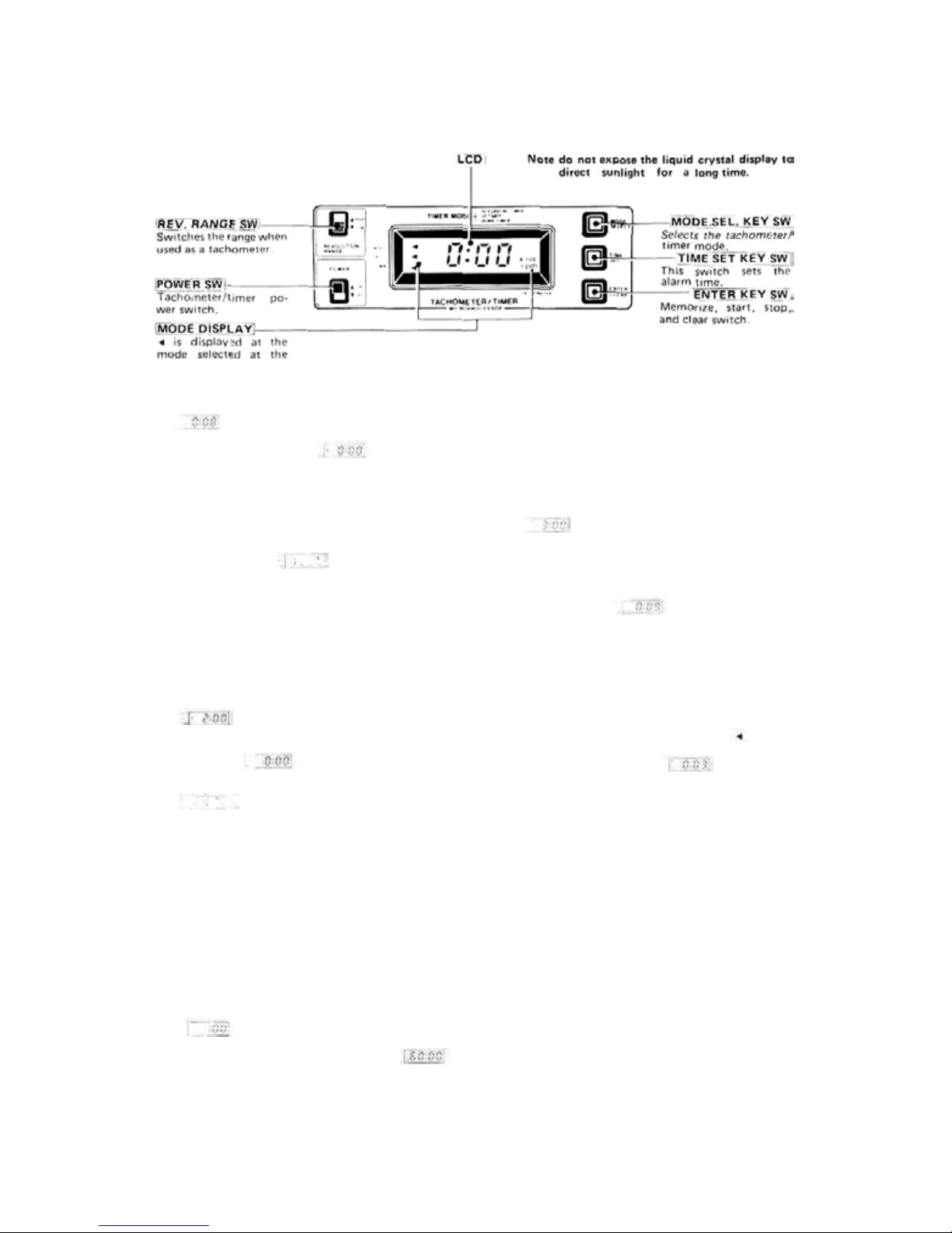
Fig.
MODE SEL K EY SW.
23
2 UP TIMER
Set the tachometer/timer POWER switch to ON.
key switch at the upper right-hand corner one time.
The display changes to , and the UP
TIMER mode is selected. When the ENTER key
switch at the bottom right-hand corner is pressed, a
beep is head and the timer starts and th e second
digit of the display changes every second. A beep is
produced every minute to indicate the passage of
time. To stop counting, press the ENTER key
switch again. The usage tim e i s displayed on t he display. For example, S means that 12 minutes
05 seconds had elapsed. The UP TIMER mode can
be used as a second stop watch. To clear the dis-
10
play, press the ENTER key switch again.
is displayed. Next, press the MODE.SEL
ALARM SETTING
The alarm can be set with the TIME SET key. Clear
the display, by pressing the ENTER key, then press
the TIME SET key twice.
two minutes was set. Next, press the ENTER key
once to memorize this two minutes The display
changes to and is memorized. Start the
timer by pressing the ENTER key. The display
changes every second. When the display reaches
a second, to indicate that two minutes have
elapsed. Thereafter the timer continues to count
up to 60 minutes. If the TIME SET key is pressed
and held for two seconds or longer when memorizing the alarm time, the time is set in five minute
steps and the set alarm times are memorized until
the power is turned off or reset. If the timer is
started without setting the time after the display
has been cleared, the previously set alarm time
remains effective. An arbitrary alarm time up to
59 minutes can be set.
appears on the display indicating that
5 1 fhe timer keeps ten times, every once
second from 10 seconds before the end of the
count-down, the same as the UP TIMER.
TIME AND ALARM SETTING
Set the time and alarm with the TIME SET key,
the same as the UP TIMER. To set the alarm to
at the display, clear the display by
pressing the ENTER key, then press the TIME
SET key three times. Next, memorize this time
by pressing the ENTER key again. The display
begins to count down in seconds. When the display begins to count down in seconds. When the
display reaches the timer begins to
keep every second to indicate that three minutes
have elapsed. If the TIME SET key is pressed
and held for two or more seconds, the time is set
in five minute steps, the same as th e UP COUNTER, and the alarm can be set to any desired
time up to 33 minutes.
4) INTEGRATING TIMER
Set the tachometer/timer POWER switch and the
transmitter power switch to ON. The blinks,
counting begins, and the elapsed time is displayed
in minutes. For example, indicates that
three minutes have elapsed. If the transmitter
power swi tch is set to OF F, counting stops. When
the transmitter power switch is turned back on,
counting continues. The integrating timer function can be started and stopped as long as the
tachometer/timer POWER switch is on even if
another mode is selected with the MODE.SEL
key. This can be used to monitor the transmitter
operating time If the ENTER key is pressed in
the INTEGRATING TIMER mode, the old integrating time is cleared and a new count begins.
This can be used to forecast the remaining
battery capacity and other applications.
Nicd
(3 DOWN TIMER
Set the tachometer/timer POWER switch to ON
and press the MODE S EL key twice.
appears on the display to indicate that
the DOWN TIMER mode was selected. Next,
press the ENTER key. The timer keeps.
appears on the display, and the display begins to
count down every second. The timer keeps every
28 Tachometer sensor connector
The tachometer sensor connectstothis
described in the preceding item.
When this connector and charging
not in use, cover them with the rubber-backed cover
supplied.
connector as
connector [29] are
Page 13

29 Charging and DSC (Direct Servo
1
Controller) connector
This connector is used as both the internal Nicad
battery charging connector and the DSC con-
nector.
Always charge the battery before use.
•Connect the DIN connector of the FBC-8B(2) charger
to the transmitter charging connector and the 3P con-
nector to the receiver/servo NR-4J battery, and plug
the charger int o a 120 V AC outlet as shown in Fig. 24.
The battery can a lso be charged through t he DSC-CHG
cord by installing the CHG adaptor t o the charger as
shown in Fig. 24. The NR-4J receiver/servo Nicad bat-
tery can be charged while inside the aircraft.
•Normally charge the battery for about 15 hours.
When the battery
has
not
been
used
for some
time,
discharge it 2 to 3 times before charging.
(Leaving the battery discharged for a long time will
lower the battery capacity and shorten the battery
life.)
•The
transmitter
and
receiver
Nicad
batteries
can
be
charged simultaneously or independently.
•A fully charged transmitter battery can be used for
about 10 flights of 10 minutes each. The receiver and
servo NR-4J Nicad battery can be used for about 4
flights when used as a common power supply with the
rate gyro and for about 6 flights when a separate rate
gyro power supply is used.
Notes:
(1) First, connect to TX Nicd and red lamp goes on
(2) Then, connect to RX Nicd after connecting,
L,E,D, changes color from red to greenish red
(orange) which indicates that both TX and RX
Nicds are being charged.
In
case
of
(3)
separate charging,
be: RX Nicd - Green T X Nicd - Red
L.E.D,
color
will
•The
direct
servo
control
nals from the transmitter directly to terminal C of
the receiver through a wire and controls the servos
without turning on the transmitter. It is extremely
convenient when ftying on the same band during
competitions, etc.
•Make the connections shown in Fig. 24. Connecting ihe special DSC-CHG cord w ith tab to receiver
terminals C and installing it to the side of t he aircraft
fuselage for convenience.
•Whe n the DIN connectorofthe DSC cord is connected to th e DSC connector 29, th e power to the
encoder inside the transmitter is turned on. Se; the
transmitter power switch to OFF.
•When not using the DSC. disconnect the DIN connector.
•To operate the servos, turn on the receiver and
servo switches.
system connects the
sig-
1
Page 14

30 Power switch
Transmitter lock-type power switch. To turn the switch
on and off, pull the knob forward and set it to the desired position.
31 Antenna
Strong 1m 10cm telescoping antenna. Extend the antenna to its f ull height when using the transmitter. The
antenna will lock in place with a click when pulled up
to
its full height.
32 Level meter
•This meter indicates the transmitter battery voltage
and output power (power mete r).
•When the antenna [31] is fully extended and the power
switch [30] is set to ON, the pointer should deflect
the whi te zone.
•If the transmitter RF module [35] is removed, the
level meter
switch [30] is set to ON.
• If the meter pointer deflects to the red zone, indicating that the Nicd battery voltage is low. the range of
the radiowaves will become shorter and the tachometer/timer
meter pointer deflects to the boundary between the
white and red zones, recharge the battery.
pointer
will
not
deflect
even
[27]
battery alarm [5] will operate. If the
if
the
power
33 Rudder button
•While this button is being pressed, the rudder moves
to the deflection angle preset at trimmer [17] on the
trimmer panel at the back of the transmitter. After
the time set a t trimmer [18] elapses, the rudder servo
returns to the neutral position. This is convenient
when making 540" turns.
•The
rudder
servo
left and
right
throw
can
be
set
trimmer [17] . When fail safe switch [19] is set to the INH
position, the rudder button [33] becomes inoperative.
When the fail safe switch is set to the RUD.REV
position, the rudder button becomes operative.
with
34 Hovering memory switch
•This switch turns the memory function which memorizes the rudder mixing hovering point on and off.
When it is set to OFF, the revolution mixing knobs
[17] and [18] become inoperative.
•When this switch is set to ON when hovering,
position of the throttle lever [3] is memorized.
•The revolution mixing up knob
mixing down knob [18] can be independently adjusted
and set from the throttle lever 3 .
•Mixing can be adjusted within this range with the High
revolution mixing up knob
17
Throttle lever hovering posi
tion (Position at which the
hovering memory switch 36
was
set
to
ON.)
[17]
and revolution
Mixing can be adjusted with-
in this range with the revolu-
tion mixing down knob 18
[
Fig.
the
25
35 Transmitter RF module
Change this module t o switch frequency among
different bands.
to
Transmitter
crystal
Fig.
26
36 FS set button
This pushbutton switch is used when setting the fail
safe servo position.
FS.SET
Fjg, 27 signals to the receiver.
When this button is pressed when the
function select switch
mer panel [38] at the back of the transmitter is set to the FS ALL or FS
SELECT position and the transmitter
sticks are set to the desired servo positions, the transmitter memorizes those
servo positions and simultaneously
Since this data is automatically transmitted every 60 seconds thereafter,
pressing the button at every flight is
unnecessary. After the servo position
data has been se t, set sw itch [35] to the
OFF position to prevent erroneous
setting.
During fail safe data transmission, lamp
[A] of monitor lamps
mentarily and transmission of the data
is then confirmed.
[35]
[24]
goes out mo-
on the trim-
Page 15

37 Back cover
To operate the trimmers and switches on the trimmer
panel [38] , remove this cover as shown in Fig. 28.
Remove the back cover by pulling stoppers in
the direction of arrows.
Fig.
28
38 Trimmer panel
Switch and adjust the trimmers and switches on this
panel with the small flat blade screwdriver supplied.
A Ailerons
1. Ailerons dual rate trimmer
This trimmer sets the aileron deflection
angle when the aileron dual rate switch
[14] is set to the ON position.
The deflection angle is adjustable from
40% to 100% of the total travel. When
the dual rate switch is set to ON, the
servo throw can be set to an arbitrary
angle smaller than that when the dual
rate switch is OFF (normal) as shown
in Fig. 30. Use the throw matched to the helicopter and maneuvers
be performed.
2. LINEAR-VTR switch
This switch switches the travel linearity
of the aileron servo when the aileron
dual rate switch
tion.
•When this switch is set t o the LINEAR position, servo tracking is directly
proportional to the deflection of the
transmitter stick as shown by curve
of
Fig.
30.
•When this
(Variable Trace Ratio) position,
maximum servo throw is the same
LINEAR shown in Fig. 32. However,
Fig.
31
Fig. 32 shows the servo tracking operation when
dual r at e sw itc h is O F F and when switch is set
to
the VTR position.
to
servo tracking is the same as the dual
rate switch ON up to about 80% of the
total travel. Servo tracking then increases abruptly up to the same throw
as
dual rat e OFF. T h i s tracking method
resembles
easy to use.
Servo tracking can be set
within this range wi t h the
dual rate trimmer.
[14]
is in the O FF posi-
switch is set to the VT R
exponential operation and is
B
the
as
13
Dual rate switch OFF
(Switch 2 in LINEAR position)
When the dual rate switch
is ON, the servo throw can
be adjusted (within this
range) with the dual rate
trimmer,
FIG 30
When the dual rat e switch is
set to ON, operation is the
same as dual rate ON at
LINEAR.
Fig.
32
Page 16
B Pitch
A Inverted flight low-side trimmer
B Inverted flight high-side trimmer
• The inverted flight function
can be turned on and off
with the [c] inverted flight
FS
switch on the trimmer
panel at t he back of t he s et .
INVERT: Inverted flight
INH
• When the [C] switch is in the
INVERT (function ON) position, normal flight - inverted flight switching can
be performed with the [26]
Inverted flight ON-OFF
swi tch at the side top corner of th e transmitter.
* When the [26] s witch is
pushed back, normal flight
is selected. At this time,
the pitch can be adjusted
with trimmers [3 , 4 , 5,
6 , and 7] as usual. When
C Inverted flight
FS switch
Fig.
33
14
the [26] switch is pulled
forward, inverted flight is
selected. At this time, the
pitch control servo, elevator servo, and rudder servo
are reversed and the pitch
control servo low-side and
high-side throws can be ad-
justed
function ON
: Inverted flight
function OFF
with trimmer A and
B.
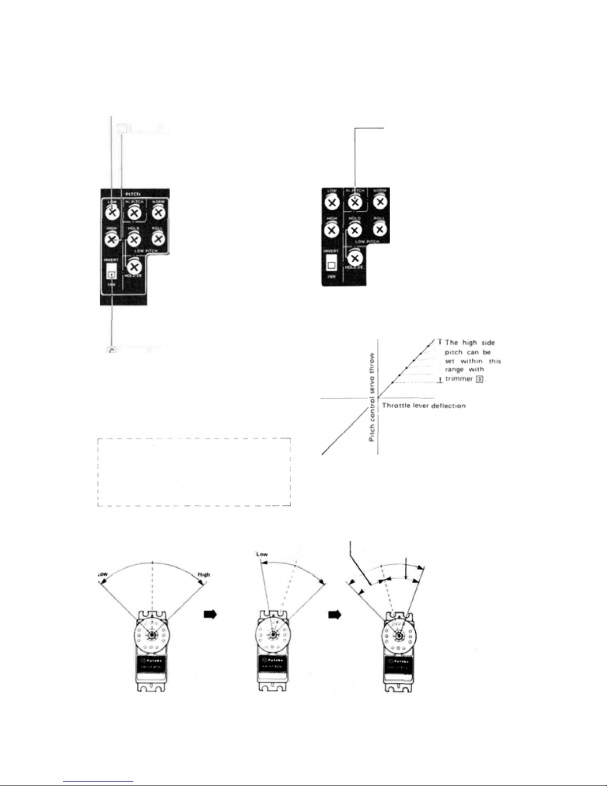
3 High side pitch trimmer.
Adjusts the high side pitch
from about 60% of the full
throw of the pitch control
servo as shown in Fig. 35.
Whe n the [C] inverted flight FS switch and [26]
Inverted flight ON-OFF switch are switched,
the A inverted flight low-side trimmer and
inverted flight high-side trimmer operate the
pitch control servo (servo connected to channel
6 of the receiver) as shown in the figure.
Fig.
34
Throttle lever
neutral
When switch [C] is set
to the INH position,
the pitch cont rol servo
operates normally.
B
Throttle lever
neutral
When the [C] switch
is in the INVERT position and the [26]
switc h is pushed back
(INVERT OFF)
[NORMAL FLIGHT]
Can be adjusted and set over this range with
trimmer B
Can be adjusted and set over
lever
this
range
with
Low
When
is in the INVERT position and the [26]
switch is pulled forward (INVERT ON)
(INVERTED FLIGHT]
High High
Throttle
neutral
trimmer A
the [C]
Fig.
35
switch
Page 17

Fig.
5
37
4. Normal pitch trimmer
Adjusted to match normal
flight.
5. This trimmer sets the low
pitch (minus pitch) when the
throttle hold switch
ON. It is adjusted to the
auto-rotation pitch.
6. This trimmer adjusts the low
pitch (minus p itch) when the
idle up [2] switch
It is used during rolls, etc.
7. Hold delay trimmer. This
trimmer adjusts the delay
time the pitch servo operates
when the throttle hold
switch
[23]
operating time of 0 to
2 seconds can be set.
8. This trimmer sets the
9. Idle up 1 point trim-
is set to ON. An
throttle servo stop point
when the throttle hold
switch
[23]
The stop point can be
set as described in the
throttle hold swit ch
section on on page 6.
When the trimmer is
turned clockwise, the
throttle servo moves to
the slow side.
mer. For a description
of this trimmer,
page 5 and Fig.
When the trimmer is
turned counterclockwise, the idle point
moves to th e low side.
[23]
[21]
is ON.
about
is set to ON.
see
10.
[23]
12. Throttle hold switch
fail safe switch
•When this switch is set to
the T.HOLD position,
is
14. Idle up 2 switch [21] fail safe switch
•When this switch is set to the IDLE2 side, the idle
up 2 function operates and the ID LE UP 2 monitor lamp comes on.
•When this switch is set to the INH side, the idle up
2 function does not operate even if the idle up 2
switch
[21]
is set to ON.
the throttle hold function operates and the
TH.HOLD monitor lamp
comes on.
• When this switch is set
the INH side, the throttle
hold function does not
operate even if the throttle hold switch
to
ON.
13 Idle up 1
fail safe switch
• When this switch is set to
the IDLE1 position, the
idle up 1 function operates and the IDL E UP I
monitor lamp comes on.
• When this switch is set
the INH side, the idle up
1 function does not
operate even if the idle
up 1 switch
ON.
switch [19]
[19]
[23]
to
[23]isset
to
is set to
1
D. Rudder
15. Rudder servo acceleration amount trimmer
•When hovering is stable, but the tail yaws a little
during takeoff, reduce the acceleration with this
trimmer until the tail no longer yaws.
10. This trimmer adjusts
Fig.
38
11. Idle up 2 point trim-
the idle up amount of
the throttle servo when
the idle up 2 switch
[21]is set
idle up amount can be
set as described in the
idle up 2 switch
section on page 5 and
in Fig. 11. When the
trimmer is turned counterclockwise, the idle
up amount decreases.
mer. For a description
of this trimmer, see the
page 5 and Fig. 11.
When the trimmer is
turned
wise, the idle up point
moves to t he low side.
to
ON. The
counterclock-
[21]
Fig.
40
•The
acceleration
fers with fixed pitch helicopters. The acceleration
amount can be set to a maximum of amount 50% by
turning this trimmer clockwise and to a minimum of
0% by turning this trimmer
counterclockwise.
16 Revolution mixing com-
pensation trimmer
The revolution mixing
(pitch control —> rudder
mixing) can be set in the
direction in which the mix-
ing amount decreases as
shown in Fig. 41 with this
trimmer.
amount
dif-
Page 18

16
Rudder servo
Settable within
this range by
trimmer [16] .
Fig. 41
17. This trimmer sets the
rudder servo throw and
direction when the rudder
button [33] is set to ON
(pressed). The servo throw
can be adjusted up to the
total travel.
18. Rudder time trimmer
This trimmer
the rudder servo stops at a
fixed deflection when the
rudder button [33] is pressed. A time from 0 to
about 3 seconds can be set.
19.Rudder button fail safe
Fig.
42
22. Revolution
trimmer [15] d irection switching and function OFF
switch
•When the main rotor turns clockwise, set this switch
to the R position. If the main rotor rotates counterclockwise, set this switch to the L position. (The
linkage may als o be reversed.)
•When the switch is set to the
revolution
turned off.
are
[17]
[17]
and [18]
switch
When this switch is set to
the RUD.REV position,
the rudder button operates. When it is set to the
INH side, the rudder but-
ton becomes inoperative.
20. Rudder dual
This trimmer adjusts the
rudder servo throw when
the
rudder dual rat e sw it c h
[16]
is
same functions as the aileron dual rate trimmer [1]
described on page 13.
221 LINEAR <->VTR switch.
This switch has the same
functions as the aileron
LINEAR <-> VTR switch
described on page 13.
and
[18]
and
and acceleration [15] functions
sets
the
time
rate
trimmer
set
to ON. It
acceleration
center position, the
has
mixing
the
E. Elevator
23. Elevator dual rate trimmer
This trimmer adjusts t he elevator servo throw when
the elevator dual rate switch [15] is set to ON. It has
the same functions as the aileron dual rate trimmer
[1] described on page 13.
24. LINEAR <-> VTR
This switch has the same
functions as the aileron
LINEAR <-> VTR switch
described on page 13.
25. Thi s s wit ch is used to select
aileron dual rate and elevator dual rate simultaneous
ON-OFF or separate ONOFF.
• When th i s switch is set to the
lower position, the aileron
dual rate switch [14] and
elevator dual rate switch
can be turned on and off
separately.
•When this switch is set
Fig.
44
F.
2nd
ATV
ATV is the abbreviation of Adjustable Travel Volume.
It is a device which allows independent a djustment of
the servo left and right (up and down) throw without
affecting the neutral position. Because of the engine
torque, precision of the model, and for other reasons,
the radius of left and right turns is always different
even if the left and right steering throws are perfectly
matched. The A T V is most convenient when lef t tu r ns
are good, but right turns are to sharp. In this case, left
and right turns of the same radius can be easily made
by reducing the servo right throw slightly. The aileron
and elevator 2nd ATV is the conventional trimmer
type ATV.
Aileron [26]
right
Aileron [27]
left
When the ATV trimmer is turned clockwise,
the throw increases. When it is turned counter-
clockwise, the throw decreases.
the COMB position, the
aileron and elevator dual
rates can be turned on and
off simultaneously with the
aileron dual rate switch
Set it to the position you
like best.
[28 Elevator
up
[291
Elevator
down
Fig.
45
[14].
[2]
[15]
to
Page 19

G. Cyclic Corrective Pitch Mixing (optional)
7
CCP mixing is performed after the helicopter corrective pitch and cyclic pitch control systems are electrically mixed. Since direct linkage from the servo to the
swash plate is possible by using CCP mixing, the model
can be made lighter by eliminating the intermediate
mechanism. Linkage rattle is also minimized.
30 CCPM switch
1 and 2 turn MIX ON-OFF
and switch the pitch direc-
Fig.
46
•When mounting the servos in the fuselage, mount
the CH1 servo (aileron servo) at the right side facing
the front and the CH6 servo (pitch servo) at the left
side facing the front.
•Set the CH2 (elevator) up and down directions with
the reversing switch. Next, set CH2 elevator to pitch
operation and set the switching and pitch direction
wi th CCPM SW 1 and 2.
•Check if the high, low,
elevator up
operation.
•Set aileron CH1, elevator CH2, pitch CH6, ATV, and
2nd ATV to maximum.
•Set the CCPM switch from OFF to 1 or 2 (ON).
When the CCPM switch is set to ON, th e CH1, CH2,
and CH6 servos throw is automatically set to 50% of
the total travel.
• The C H1 and CH6 deflection width is set so that the
left and right throws of the two servos at each ATV
are the same.
• Adjust the aileron left and right throws using the
2nd AT V when CH1 and CH6 operate with mixing
ON. (CH1 and CH6 can be adjusted simultaneously.)
•Check the aileron direction when CH1 & CH6
operate. Use the reversing switches to correct
aileron direction.
•The CH2 deflection
2nd
When mixing is used, the swash plate is moved up
down. Use a coaxial swash plate.
Since the servo throw is about one half of the total
travel, so that the servo horn throw must be adjusted
to
make larger at the servo horn side.
and down directions are correct by pitch
ATV.
tion when the CH2 (elevator) servo is operated as
the pitch servo.
aileron left and right, and
the
can be adjusted with ATV or
and
CH1: Reverse
CH6:Normal
CH2: Reverse
CCPM: (2)
CH1 solid line indicates reverse
CH1 dotted line in-
dicates normal
Fig.
47
CH1: Normal
CH6: Reverse
CH2: Normal
CCPM: (2)
CH6 solid line indicates reverse
CH6 dotted line indicates normal
When CH2 servo is
behind the main
rotor shaft
When the CH2 servo is in front of the main rotor
shaft, CCPM ( 1 ) and the horn rod are indicated by
the dotted lines.
When the CH2 servo
is in front of the
main rotor shaft,
CCPM (1) and the
horn rod are indicated by the dotted
lines.
Swash plate
When
CH2
Fig.
ser-
48
Cl-12 \''vo is mounted
', at the right as
\\ viewed from
'.'' the rear.
1
Page 20

H. Servo reversing switches
These switches reverse the direction of the servos.
They are very convenient when connecting the linkage.
Fig.
Rudder
Throttle
Elevator
Aileron
NORM position
: Forward
REV position
: Reverse
CH8 switch
channel
CH7 lever channel
CH6 pitch control
CH5 switch channel
49
I. ATV/FS button
•These two pushbutton switches are used for servo
deflection angle setting of ATV, FS or HOLD function; servo test start & stop; reset; battery FS memory
set,
etc.
•USING AT V (Aileron ATV
taken as an example)
1 First, set switch [K] [35] to the AT V side.
2 Next, set CHANNEL
1 (aileron) position.
3 Set the transmitter and receiver power switches to
ON, and check the operation of the servos.
4 Set the aileron stick for full right rudder, hold it in
that position, and s et the aileron right throw to the
desired angle by
5 To set aileron left, hold the aile ron stick in the full
left position and set the servo throw with buttons
[33] and [32]
(ATV can be adjusted in 64 steps. ATV can be continuously varied by pressing and holding the button f or more than 1.5 seconds.)
6 For th e other channels,
CHANNEL SELECT switch [J] [34] and operate
ATV.
7 At the end of adjustment, set switch [K] [35] to the
center OF F position and set switch [J] [34] to OFF
position.
8 This ATV function is memorized
switch is set to off , the AT V function
transistor Nicd is fully discharge.
9 When clearing the ATV, set switch [35] to RESET
and switch [34]
and [33] simultaneously. ATCs of a ll channels are
cleared and servos deflect their 100% angle.
pressing
.
to
position 2 and
SELECT switch
buttons [33] and [32]
select
the
channel
even if the power
press
[J] [34]
to the
.
with
the
is lost if the
buttons [32]
18
[32]This
pushbutton
1 Making the ATV servo deflection angle larger.
2 Turning the FS function on.
3 Starting the servo test.
—[33] This pushbutton sw i tc h is used when:
1
Making the ATV servo deflection angle smaller.
2 Turning the HOLD function on.
3 Stopping the servo test.
When button [32] and [33] are pressed at the same time,
reset or battery FS memory setting is possible. At this
time, lamp [ A] of monitor lamps [24] goes out momentarily so that setting can be monitored.
switch
is
used
when:
Fig.
ATV SETTING
Press button [32] and [33] while
holding the aileron stick in the
full position.
Switch switches [J] [34] and [K] [35]
51
HOW TO USE FS (Fail Safe)
(Throttle channel as an example.)
1 First, set switch [K] [35]toFS SELECT.
2 Set the transmitter and receiver power switches
ON, and check the movement of each servo.
3 Next, while switching the channel select switch [34]
from 1 to 8 in order, set the channels to be used
with FS, with button [32] and set the channels to
be used with HOLD, with button [33]. In this example, set 3 (throttle) to FS with button [3 2 ] .
4 Set the throttle lever to the slowest position, and
press
the FS
set
transmitter.
5 The 1 — 4 above set low throttle for the FS
function. After setting FS function, turn switch
[35] and [34]
transmitter power switc h to OFF.
button
to
OFF. Test
[36]on the
fail
safe
back
by
of
turning
the
to
the
Page 21

Each servo moves to the neutral position except
the throttle servo which moves to the slow position
that was just set.
6 Pail safe for all channels can be set with one touch
by setting the sticks and switches of the all channel
to any predetermined position
button [36] one time.
7 The FS function can be set for all channels and any
servo deflection angle in this manner. When using
FS in all channels the function select switch must
be set to the FS A LL position.
8 Since this FS function is memorized by the trans-
mitter which transmits the data every 60 seconds,
even when the receiver power sw itch is set to OFF,
resetting is unnecessary.
9 After those settings, set switch [35]
vent erroneous setting.
10 When button [36] is pressed twice, setting FS in
flight, etc., the servo position of the second is
memorized in FS and transmitted.
11 To clear the preset FS information, set switch [35]
to reset position switch [34] to position 1 and press
buttons [32] and [33] simultaneously. FS of all the
channels is cleared and all the servos move to the
neutral position.
and
pressing the FS
to
OFF-to pre-
FS function/HOLD function
The FS function is turned on with button [32] and
the
HOLD
previously described.
function
FS (Fail safe function)
FS is a function which moves the servo of each channel to a position preset on the transmitter when no
radio waves are received by the receiver from the
transmitter or when continuous strong noise is received for about one second or longer. The set operates
by the hold mode in one second and then, by the FS
mode. When the noise or interference disappears and
normal radio waves are received in approximately one
second, FS is released.
HOLD (Hold function)
HOLD is a function which stops all the servos specified by
HOLD
command immediately before the erroneous signal
was received.
When the noise, interference, etc. disappears and
normal radio waves are received, HOLD is released.
Set the FS function and HOLD function as you like.
•The
operation of the
ting the transmitter and receiver power switches to
ON.
•When switch [35] is switched to TEST-A, the servos
move half-side first and then, come back to neutral
and repeat the other-half from channel 1 to channel
8. (Channel select switch [34] to TEST-ALL position
at this time.) The servos set by the channel select
switch do not operate. (If set to 5, the landing gear
servo does not operate.)
is
turned
(by
button [33] to the
servos
can
on
with
button [33]
be checked by
last
as
correct
set-
•When
switch [35]
operate linearly over their full travel. (Channel select
switch [34] in TEST-ALL position at this time.) Only
the servos set at the channel select switch are oper-
ated.
•
The
servo
is
stopped
test
by
pressing
is
started
is
switch
button [33].
Fig.
to
TEST-B. all
by pressing
52
the
button [32]
servos
BFS MEMORY SETTING
1 BFS (Battery fail safe function) is a function which
moves the throttle servo to a preset position as set
by the FS when there is only a small amount of
power left in the receiver Nicd battery. (If not
set, the throttle servo will be set to medium slow
automatically.)
2 The BFS setting method is the same
usage method previously described.
3 To release the throttle servo from the preset posi-
tion
set
by BFS and
throttle lever in the slow direction. When the
throttle lever reaches a certain point, BPS will be
released and the throttle servo can be controlled
for 36 seconds.
4 Setting this throttle lever point is called BFS
memory setting, and is done a s follows:
•First, set switch [35] to BFS MEMO.SET and set
switch [3 4] to position [3] (throttle channel.).
• Next, while watching the movement of the servo,
set the throttle lever to the desired position (between slow and medium s low recommended) and
press buttons [32] and [33] simultaneously. This
completes BFS memory setting.
•This
memory allows
position, slowtohigh.
•Lamp
[A]
of
the
monitor
BFS
[35]
point where BFS is released, this allows BFS to
be checked.
•When there is little power left in the receiver
Nicd battery, the throttle servo automatically
stops at the position set by BFS, BFS is released
when the throttle lever is moved to the memorized point. Throttle can th en be controlled for 36
seconds by throttle lever
•When
immediately lower the throttle lever to release
BFS. then quickly land.
Function setting can be confirmed by means of lamp
[A] of m onitor lamps
1 When switch
When lamp [A] is on, HOLD and
off,
FS.
2 When switch [35] set to ALL FS, off .
3 When switch [35] se t to ATV and button [32] or [33]
pressed, blink.
regain
control, lower the
setting
the throttle to any
lamps [24]
status
comes
[24].
is at FS SELECT
goes
out
during
when lamp
as the FS
out
at
the
flight,
[A] is
and
19
Page 22

J Channel select switch
•This
switch
selects
FS, when used in conjunction with item [1] ATV/FS
button previously described. It is also the select
switch for servo test and th e switch which selects the
channel to be by switch [35] RESET.
Fig.
53
the channel
[34] Channel select switch
to
be
set
by
ATV
or
K Function select switch
•This
switch
selects
ATV,
FS,
servo
test,
BFS memory setting as described at [I] ATV/FS
button.
• Normally set it to OFF.
1FS ALL
Switch to this position when setting fail safe for all
channels, FS is described in the "HOW TO USE
FS" section.
2 FS
3
SELECT
This position allows setting of fail safe and hold as
described in the "HOW TO USE FS" section.
ATV
This position allows setting ATV as described in
the "HOW TO USE ATV" section.
reset,
and
4 TEST A
Relationship among channel select switch number,
servo and reset.
At
switch [35]
No.
ATV, TEST A.B
1
Aileron
Elevator
2
Throttle
3
4
Rudder
Channel 5 switch
5
Channel 6 pitch
6
7
Channel 7 knob
Channel 8 switch
8
20
RESET &
TEST ALL
OFF
FS
SELECT,
All the servos are
operated at servo
test.
Usually set to this OFF position.
At switch [35]
RESET
FS (fail safe)
ATV
BFS memory
FS,
ATV,
memory are reset
simultaneously.
and BFS
This position allows servo
"SERVO TEST" section.
5 TEST B
This position allows servo test B as described in the
"SERVO TEST" section.
6 BFS MEMO SET
Switch to this position when setting the BFS release
point
as
MEMORY SETTING" section.
7
OFF
Normally
described in the "BATTERY
set to this position.
test A as described in the
FS
35 Function select switch
39 Trainer cord socket
40 Trainer switch
Push on/self-off switch. The transmitter connected
by the trainer cord (M-TC) operates and when it is
OFF, your-own transmitter only operates.
Connect the transmitters with the trainer cord (MTC-FM, purchased separately) as shown in Fig. 55.
When the switch is in the ON (push) position, the
student's transmitter operates and whe n the switch
is in the OFF position, the instructor's transmitter
Operates. The transmitter at which the trainer
switch is operated on-off becomes the inst ruct or's.
Instructor transmitter
(Power switch ON and transmitter operating)
Fig.
54
Page 23

RECEIVER AND SERVOS
1
FS (Fail safe) and HOLD functions
•The HOLD function holds all the servos
sition immediately before a bad set of signal is
received. When normal radio waves arrive, or the
interference disappears, hold is released.
•The
FAIL
SAFE
preset position set at the transmitter, one second
after interference is received. When the interference
disappears, FAI L SAFE is released.
Although already described in the transmitter section,
FS
servo of all the channels to the position preset at the
transmitter when continuous strong noise is received
set operates in the hold mode during the one second
the noise or interference is received.
(fail
by the receiver for about one second or longer. The
function
safe)
moves the
is a function
which
at the
servos
moves
po-
to
the
B.F.S, (battery fail safe) function
The B.F.S, locks the throttle channel only in the position preset by FS when there is very little power left
in the receiver and servo side Nicd battery. (If nothing
is set, the throttle channel becomes medium slow.)
The throttle channel can be released and operated for
36 seconds by moving the throttle stick in the slow
direction. After 36 seconds, th e set reenters the B.F.S.
mode. When the set enters the B.F.S, state, immediately land the aircraft.
•Connect
tery firmly as shown in Fig. 57. Then extend
the transmitter and receiver antennas to their
full length.
•Set the transmitter power switch to ON, then
set the receiver switch to ON. The servos stop
near the neutral position. Operate the transmit-
ter sticks and check that each servo follows the
movement of the stick.
•Connect the pushrod to each servo horn, then
check if the direction of travel of each servo
matches the direction of operation of its transmitter stick. If the direction of servo travel is
opposite the desired direction, switch the servo
reversing switch.
•Operate each servo to its full stroke and check
if the pushrod binds or is l oose. Unreasonable
force
for the horns, but will also cause the battery to
run down quickly. Always make the stroke of
the
receiver,
servo
switch,
and
bat-
applied to the servo horns is not only bad
a
each control mechanism somewhat larger than
the full stroke (including the trim component)
of the servo horn. Adjust the servo horns so
they move smoothly even when the trim lever
and stick are operated simultaneously in the
same direction.
•Be alert for noise.
This set has noise rejection circuits, however,
noiseless parts are recommended.
•When installing the switch harness, cut a rectangular hole somewhat
larger
than the
full
stroke of the switch, and install the switch so it
moves smoothly from ON to OFF. Install the
switch inside the fuselage and attach a piece of
wire to the switch so it can be turned on and
of f fr om the outside. Install the switch where it
will not be exposed to engine oil, dust, etc.
•Even though the receiver antenna may
appear
to be to o long, do not cu t or bundle it.
•Install the servos securely. Tighten the mounting screws until the rubber damper is slightly
If
the
screws
are
too
tight,
crushed.
the cushion-
ing affect of the rubber damper will be lost.
•The
crystal
can
be
changed
from the outside
of the receiver case. Always use the Futaba
transmitter/receiver matched crystal set to
change the band.
•
A spare
servo
horn
is
supplied
with
the
set.
Use this horn as needed.
•Use extension cords as needed.
•Wrap the receiver in sponge rubber. Waterand dust-proof the receiver by placing it in a
plastic bag and wrapping a rubber band around
the mouth of the bag. Do the same with the
receiver/servo battery.
•Use the rubber bands wrapped around the re-
ceiver to hold the servo and switch leads.
•After mounting is complete, recheck each part,
then check the transmitting range by making
the transmitter antenna as short as possible, extending the receiver antenna to its full length,
and operating the transmitter from a distance
of 20m to 30m from the receiver. The move-
ment of each servo should follow the movement of each transmitter stick.
2
Page 24

PCM RECEIVER FP-R118GP
Antenna wire
Receiver, servo switch, an d battery
connections
Antenna
wire
AEC-3
Extension cord
22
Crystal
Fig. 5 6
Error lamp
• System checking can be performed with this lamp.
•When the receiver and servo side N icd is connected and this LED is on, radiowaves are not being
received from the transmitter, check to be sure
the frequency is correct.
the lamp being on.
•When strong noise has been received, or the
radiowaves from the transmitter are intermittently interrupted, this lamp will blink.
This usually is not a problem.
Checkingispossible by
Remove the receiver crystal
pulling it in this direction.
by
PCM receiver
FP R118GP
Power switch
SWH-5 (R4-SWJ)
Charging connector
Receiver crystal
Fig.
58
NR-4J
Pay careful attention to the
connector polarity.
Fig.
59
Page 25

Aileron servo
2
Elevator servo
3
Throttle servo
4
Rudder servo (When
gyro is used, this servo
connects to the receiver
through the rate gyro.)
5.
Landing gear servo, or rate
gyro output switching
connector
6
Pitch control servo
8SSHP
a rate
4 servos
Fig.
57
23
Connected servo (rudder servo
for helicopter) neutral position
trimmer. (This trimmer is
operative even when the
control box power switch is
to OFF.)
Connects to
receiver CH5
(Gyro output
switching)
Gyro output
polarity switch
Control amp
set
Gyro body
Gyro output trimmer
Control box
Five battery pack 6V connector Motor regulated
power supply. (Insert the jumper connectors
when the power supply is shared with the receiver.)
(C) connector Red Jumper connector
Page 26

•General adjustments
Make the basic fuselage linkages and adjustments according to the helicopter manufac-
turer's assembly and adjustment instructions.
1. Check the direction of operation of each servo. If
the servo rotates in the wrong direction, switch the
setting of the pertinent servo reserving switch.
2. Set the idle up [1] switch
[21]
and throttle hold switch [23] to OFF (to the
opposite side).
3. Set the hovering pitch lever [6] and hovering throttl e knob [22] to about the center of the scale.
4. Check the left and r ight (up a nd down) throw of
each servo. If the throw is wrong, correct it with
the ATV trimmer and by changing the hole position of the servo horn, etc.
(5 Set the throttle lever
um slow position and set the hovering memory
switch [34] to ON.
Set the compensation setting amount to 0 by
turning the hovering mix compensation setting
trimmer [16] on the trimmer panel at the back of
the transmitter.
6 Set the revolution mixing up knob [17] to about
division 5 and the revolution mixing down knob
[18] to about division 7.
7. Check the pitch control -> rudder mixing direction.
24
If the direction is wrong, correct it with switch [22]
on the trimmer panel on the back of the transmitter.
8. Recheck the operating and mixing directions of
each servo, and set the hovering memory switch
to
OFF,
[34]
9. Check the
o Pull throttle when throttle lever in high position
o Set the ATL (Adjustable Throttle Limiter) to the
10 Turn the normal pitch trimmer [4] (high side pitch
trimmer [3] at the pitch trimmer [B] on the
trimmer panel at the back of the transmitter and
set the pitch control high side trimmer [13] to th e
maximum (upper) position. Set for maximum
pitch control servo throw when t he throttle lever
is operated over i ts fu ll stroke. Set the maximum
pitch width and set the pitch control high side
trimmer lever [13] to about the center.
engine and throttle linkage.
Zero throttle when throttle lever in maximum
slow position and throttle trim in maximum slow
position.
maximum limit. This is very convenient because
the high side does not change even if the slow
side is adjusted.
[19],
idle up [2] switch
[3]
to about the center medi-
11. Start the engine. After needle adjustment, hover
the helicopter, trim the ailerons and e levators, and
make the ma in rotor pitch larger during the next
hovering with the fuselage linkages. Then trim with
the hovering throttle knob [22] and pitch control
trimmer [6] . Adjust the throttle lever position at
hovering to 50% to 55% of its full stroke.
12. Trim
18 Rate gyro output adjustment (when FP-G152
the rudder by adjusting the linkage
rudder is in the neutral position when hovering.
13 After adjusting all the trim levers, hover and set
the hovering memory switch [34] to ON. The
memorized hovering point remains memorized
even when the transmitter power is turned of f. It
is cleared when the hovering memory switch [34] is
set
to
OFF.
14
If the helicopter slips to the right when hovering,
increase the mixing amount by turning the revolution
mixing down
helicopter slips to the left. turn the knob counterclockwise.
15 If the helicopter slips to the left when climbing
from hovering, turn the revolution mixing up
knob [17] clockwise. If the helicopter slips to the
right, turn the knob counterclockwise.
16 Next adjust the acceleration amount with trimmer
[15] of the rudder trimmers [D] on the trimmer
panel at the back of the transmitter. Although it
depends on the helicopter, it should have some
effect because of the interaction with the rate
gyro output. For fixed pitch helicopters, a pitch
of about 0 is usually suitable.
17 Adjust the normal pitch trimmer [4] of the pitch
trimmers [B] on the trimmer panel of the ideal
pitch at takeoff. Although it depends on the
helicopter, a pitc h of about 0 is usually suitable.
used)
• Hovering
Set the rate gyro control box scale to about 40%
to 80% of full scale, depending on the helicopter.
Increase the gyro output within the range at
which the tail does not swing back and forth.
• Maneuvering
Set the rate gyro control box to about 30 to 50%
of full scale, depending on th e helicopter. Adjustment within the range at which the tail does not
swing during high speed level flight is suitable.
19. Adjust the pitch control high side tr im lever [3] so
the pitch is reduced during high speed le vel flight
so that the main rotor does not load the engine.
When flying in a strong wind, increase the pitch
slightly with this lever. Adjust to the conditions
for t he time of day while flying.
side
knob
[18]
clockwise.
so the
If the
Connect the linkage so the main rotor pitch
variation width is somewhat larger than that
recommended by the helicopter manufacturer.
Page 27

AIRCRAFT ADJUSTMENTS
•Revolution Mixing Compensation Adjustment
When high speed level flight is performed with a helicopter, the tail rotor reverse torque required is small,
however the high side revolution mixing amount is
large, the fuselage will veer to the right. The power
loss by the tail rotor becomes large. (Opposite when
the main rotor rotates counterclockwise.)
If only the mix amount "up side" is reduced at the
high side about 70% of the throttle stick at this time,
maneuverability also improves and the power loss is
also reduced.
Rudder servo
•IDLE UP 1 ADJUSTMENT
1 Hover and check the throttle lever hovering posi-
tion.
2 Stop the engine, set the throttle lever to the hover-
ing position, and set the idle up 1 knob [20] to
division 10 (maximum). Adjust the idle up point
up and down with trimmer [9] of the throttle
trimmers
ter. Make this adjustment so that the throttle servo
does not operate when switch [19] is turned ON and
OFF. Idle up is maximum at this point.
3 When the idle up 1 switch [19] is set to ON, the
throttle servo operates up to the position set at the
idle up 1 knob
4 Set the idle up 1 knob
and set the throttle lever to maximum slow.
5 Next, set switch [19] to ON and turn knob [20] slowly
clockwise. While slowly accelerating the engine, set
the rotor speed to the same speed as when hovering.
6 With this setting, the change in the main rotor and
tail rotor speed from takeoff to hovering is small,
the change in the effect of the rate gyro and servos
is also small, and aerobatics are extremely easy.
[C]
on the trimmer panel at th e transmit-
[20]
.
[20]
to 0, start the engine,
Throttle servo
25
1. Fly in level flight at full speed.
2 When the speed does not increase at high speed
flying, or when the helicopter swings to the right,
when the speed does not increase while the
helicopter rises vertically, etc., the revolution
mixing amount is probably excessive.
3 Adjust the compensation setting amount with
trimmer [16] and set it so th a t the revolution mixing
amount is reduced at throttle lever maximum.
4 The compensation setting amount should normally
be about 3 ~ 4 of Fig. 60 for fuselage system
and 4 ~ 5 tor frame system.
5 Fly at full speed again to adjust the trimmer [16]
maximum for highest acceleration at high
and vertical moving up.
6 Since the set value depends on the diameter and
shape of t he tail rotor, adjust repeatedly for maximum linearity and power.
Fig.
60
speed
The idle up amount can
be set within this range
with knob
[20].
Idle up point
can be set with
trimmer [9].
Fig.
61
Page 28
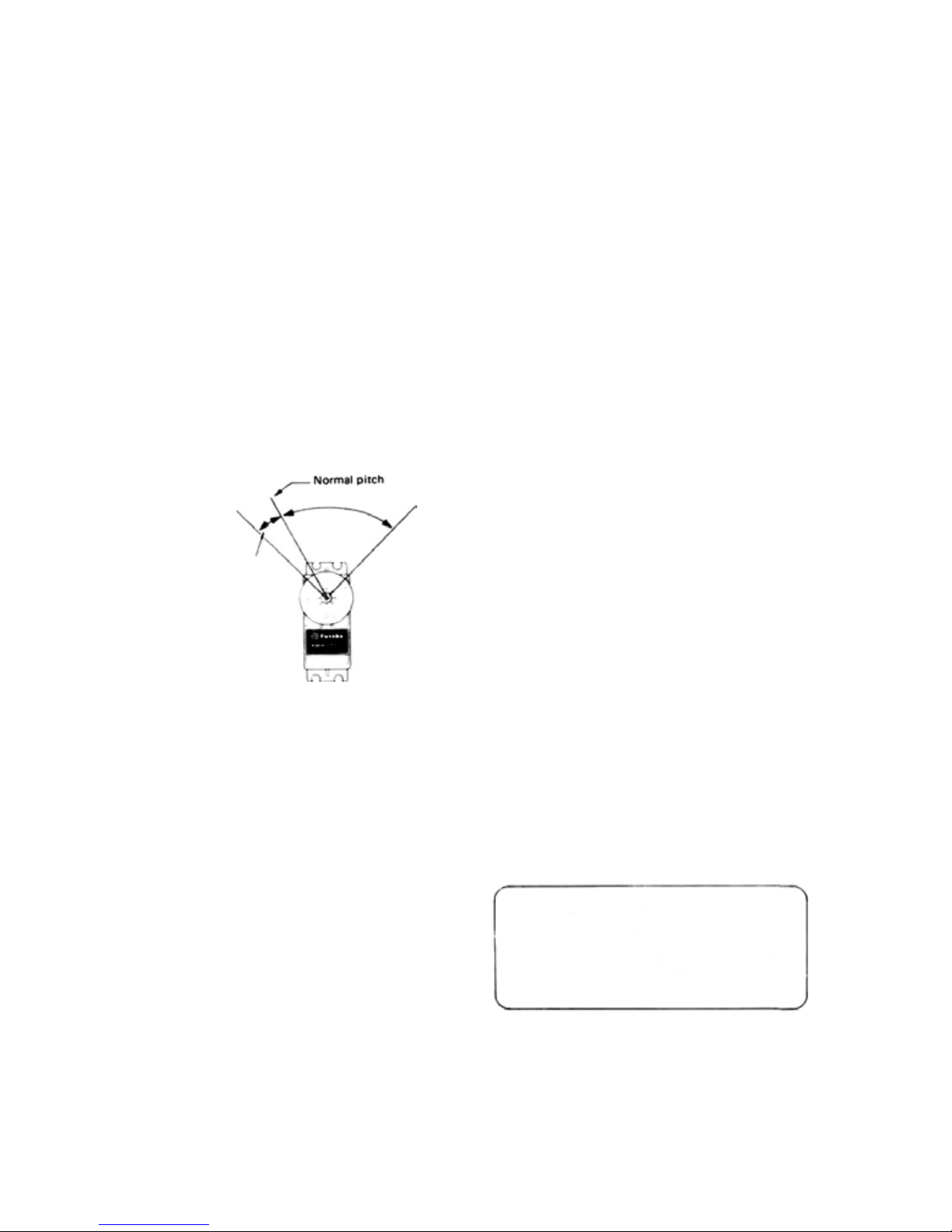
•IDLE UP 2 ADJUSTMENT
1. When the idle up 2 switch [21] is set to ON, the
idle up amount (throttle servo stop position) can
be adjusted with trimmer [10] of the throttle trimmers [C] on the trimmer panel at th e back of the
transmitter. The low side pitch can be adjusted
with trimmer [6] of the pitch trimmers [B] on the
trimmer panel on the back of the transmitter.
2 When trimmer [10] is
applied. (See Fig. 61.)
3 Set the idle up 2
patterns.
4 Adjust the low side pitch to match rolls and other
dynamic pattern with trimmer [6].
When trimmer [6] is
turned clockwise and
switch
[21]
26
position, the pitch
increases at the minus
side.
is in the ON
turned clockwise, idle up is
point trimmer [11] for dynamic
Pitch control servo
Fig.
62
4. Adjust trimmer [8] so the engine stops (throttle
fully closed) when entering auto-rotation and when
switch
[23]
slightly open) during practice.
5 Adjust the maximum pitch when switch
to
ON with the ATV button.
The pitch servo moves to the
ATV button without regard to the
pitch control high side trim lever
6 Throttle hold delay adjustment
Set the hold delay trimmer [7]
wise
• Next, perform auto-rotation. When the drop is
fast the instant throttle hold is applied, turn the
hold delay trimmer [7] and set it for a constant
drop.
•Set
required time. Normally, about 0.7 second. This
is about 30% t o 40% by trimmer position.
7 When performing auto-rotation using hold delay,
set the throttle lever to maximum slow, then im-
mediately turn on throttle hold switch
• If y ou are not familiar with auto-rotation, use
the set with the hold delay trimmer [7] turned
fully counterclockwise to 0 hold delay.
is in the ON position and idles (throttle
position set at the
[13].
to the 0 position.
the
hold
delay
trimmer [7]
full counterclock-
to
[23] is set
position of the
the
minimum
[23].
• Rudder button adjustments
1 When the rudder button [33] is pressed, the rudder
servo moves in the direction and to the angle
trimmer [17] of the rudder trimmers
at
trimmer panel at the back of th e transmitter.
2. The tim e the rudder is operated can be set with
rudder time trimmer [18] on the trimmer panel at
the back of the transmitter.
3 Set
the rudder
angle matched to 540* for stall turns and other
spinning maneuvers.
servo
throwtothe
direction and
set
[D] on the
the
•Throttle hold and throttle hold delay
adjustment for auto-rotation
1. When the throttle hold switch [23] is set t o ON, the
throttle circuit is disconnected from the throttle
lever and only pitch control can be performed with
the lever.
2. The auto-rotation pitch can be adjusted with trimmer [5] of the pitch trimmers [B] and the auto-
rotation throttle servo stop position can be adjust-
ed with trimmer [8] of the throttle trimmers
on the trimmer panel at the back of the transmitter.
3. Adjust trimmer [5] for a pitch of about minus 2
when switch [23] is ON and the throttle lever is in
the maximum position. (This pitch differs somewhat with the helicopter.)
[C]
[Fail safe switches]
After you have become completely familiar with your
set, set switches 12, 1 3, 14 , 19 and C on the trimmer
panel at the back of the transmitter to the ON position. When first using your set, practice with the
switches in the OFF (INHIB) position.
Page 29

FP-T8SSHP INVERTED FLIGHT SPECIFICATIONS
HANDLING PRECAUTIONS
• When the [C] inverted flight FS switch at the rear panel t rimmers is switched to the INVERT position, normal fl igh t <-> inverted flight switching,can
be performed with the Inverted flight ON-OFF switch.
• Note that the cyclic corrective pitch mixing
flight function are not performed simultaneously.
* When the [30] CCPM switch and [C] inverted flight FS switch are set to
ON, the CCPM function has priority.
(optional) function and inverted
FP-T8SSHP INVERTED FLIGHT SPECIFICATIONS
TRIMMER PANEL
[A] Inverted flight low-side trimmer
B] Inverted flight high-side trimmer
27
Fig. 63
[C] Inverted flight FS switch
30 CCPM switch (optional)
Page 30

• The inverted flight function can be turned on and off with the [C] inverted flight FS switch on the trimmer panel
at
the back of the set.
* INVERT: Inverted flight function ON
•When the [C] switch is in the INVERT (function ON) position, normal flight <-> inverted flight switching
INH : Inverted fligh t function OFF
performed with the [26] Inverted flight ON-OFF switch at the side top corner of the transmitter.
* When the [26] switch is pushed, normal fli ght is selected. At this time, th e pitch can be adjusted with trim-
mers [3, 4 5, 6, and 7] as usual. When the [26] switch is pulled, inverted flight is selected. At this
time, the pitch control servo, elevator servo, and rudder servo are reversed and the pitch control servo lowside and high-side throws can be adjusted with trimmer [A] and [B].
When the [C] inverted flight FS switch and [26] Inverted flight ON-OFF switch are switched, the
[A] inverted flight low-side trimmer and [B] inverted flight high-side trimmer operate the pitch
control servo (servo connected to channel 6 of the receiver) as shown in the figure.
Throttle lever
neutral
can be
Fig. 64
28
When switch [C] is set to
the INH position, the pitch
control servo operates normally.
When the [C] switch is in
the INVERT position and
the [26] switch is pushed
(INVERT OFF)
[NORMAL FLIGHT]
Can be adjusted and set
over this range with trim-
mer [B]
Can be adjusted and set
over
this range
mer [A]
When the [C] switch is in
the INVERT position and
the [26] switch is pulled
(INVERT ON)
[INVERTED
with
FLIGHT]
trim-
Page 31

INVERTED FLIGHT PREPARATIONS
• Set t he [C] inverted flight FS switch on the trimmer
panel at th e back of th e se t t o the INVERT position.
• At this time, pitch control servo, elevator servo, and
rudder servo forward <-> reverse switching can be
performed with the [26] switch and normal <-> inverted flight switching can be performed.
• Whe n the [26] switch is pulled (inverted flight func-
tion ON) when the [3] throttle lever is in the neutral
(center) position, the neutral position of the pitch
control servo moves to the plus side (pitch HIGH
side at t he rear panel).
•
When
connecting
specifications, always set the [C] switch to the
INV ERT position.
• Then adjust the set so that normal flight is normal.
the linkage
with
the inverted
flight
FLIGHT
• Pe rf or m normal flight and adjust the pitch.
• After adjustment, switch from normal
inverted flight.
There are various methods of changing from normal
flight to inverted flight. One method is to enter
inverted flight by making a half roll from straight
flight.
* First, make a half roll from straight horizontal
flight at an altitude of about 30m and when the
helicopter is exactly on its back, turn on the inverted flight function by pulling the [26] switch
back.
If
the throttle lever remain high at thi s time, the
*
posture of the helicopter will change suddenly.
Shifting to inverted flight can be performed
smoothly by lowering the throttle lever to about
medium slow.
* Learn the [26] switch switching timing,
lever operating setting, etc. by practicing normal
flight < - > inverted flight switching repeatedly.
• Next, switch from inverted straight flight to inverted
hovering.
* Lower the altitude by slowly lowering the throttle
lever.
flight to
throttle
• After adjusting normal flight, adjust inverted flight.
* Before flight, set the [26] switch to the back posi-
tion (inverted flight function ON) and set the
throttle lever to maximum slow, then set the mini-
mum pitch at inverted flight with the [A] trimmer.
* Next, set the throttle lever to maximum high and
set the maximum pitch at inverted flight with the
[B] trimmer.
* The [A] and [B] trimmers can be adjusted only
whe n the [26] switch is in the back (inverted flight
function ON) position.
* Since the [6] hovering pitch lever and [13] pitch
control high side trimmer lever control the pitch
control servo even at inverted flight, they can be
adjusted to the optimum pitch.
* At this time, when the helicopter descends slug-
gishly and the main rotor speed drops even when
the throttle lever is lowered, return to normal
flight, then land and lower the lowest pitch of
the main rotor at inverted flight with the [A] trimmer.
* Set th e [6] hovering pitch lever, etc. so that the
main rotor speed at inverted hovering and normal
hovering is about the same.
* If the difference it too large, readjust the linkage.
Finally, check the high side pitch.
* Try setting the throttle lever to maximum high at
inverted hovering.
* If the main rotor speed drops at this time, lower
the high side pitch with the [13] pitch control high
side trim lever, then land and correct the [13] lever
portion with the [B] trimmer.
(Correct with the [B] trimmer so that the [13]
lever
position
verted flight.)
is
the
same
at normal
flight
and in-
29
Page 32
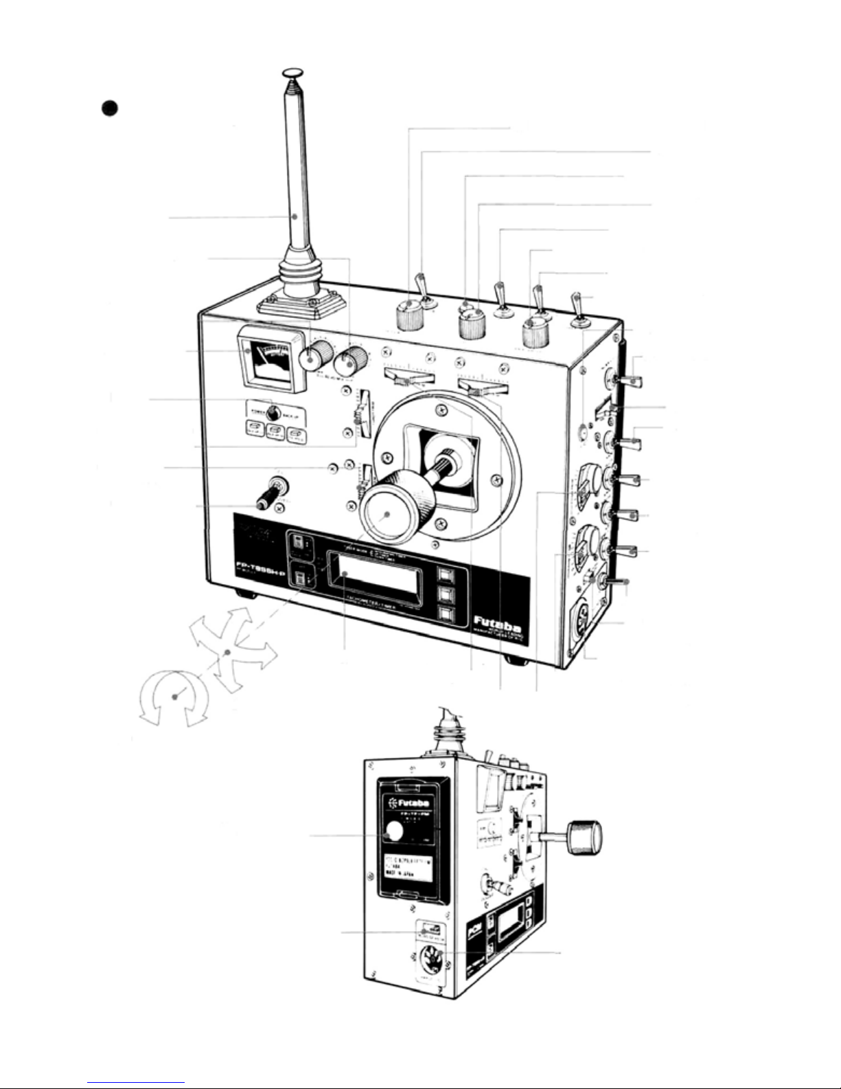
TRANSMITTER
CONTROLS
22 Hovering throttle ratcheted knob
8 CH8 switch
33 Rudder button
31 Antenna
17 Revolution mixing up side
ratcheted knob
18 Revolution mixing
down side
ratched knob
32 Level meter
24 Monitor
lamps
11Throttle
lever w/ATL
10 Elevator
trim lever
30 Power switch
4 Rudder
25 Rotative open
trim
1 Aileron
2 Elevator
gimbal stick
27
Tachotimer/timer
12 Rudder trim lever
9 Aileron trim lever
7 CH7 Knob
21 Idle up 2 switch
20 Idle up 1 ratcheted knob
19 Idle up 1 switch
23 Throttle hold switch
36 FS set buttons
26 In
verted
ON/OFF
switch
3 Throttle
15 Elevator
dual rate
switch
14 Aileron dual
rate switch
16 Rudder dual
rate switch
5 CH5 switch
(rate gyro output
switching)
40 Trainer switch
34 Hovering
memory switch
39 Trainer cord socket
6 Hovering pitch lever
13 Pitch control high side trim
lever (CH6)
Fig.1
flight
30
35 Transmitter
RF module
28 Tachometer
sensor connector
29
Charger & DSC
connector
Page 33

TRANSMITTER CONTROLS
Stick all of the packed non-slip pads at
the positions desired by the customer.
Non-slip pad
Fig.
2
A Ailerons
BPitch
CThrottle
DRudder
E Elevators
G CCPM switch
(optional)
F
2nd
H Servo reversing
ATV
I ATV/FS
buttons
38 Trimmer
37 Back cover
switches
J Channel
selector
K Function
select switch
panel
Fig.
31
3
Page 34

SPLINED HORNS
The splined horns allow shifting of
the servo neutral position at the
servo horn.
Setting and shifting the neutral
position
a) Angle divisions
Fig.
65
1) The splined horn has 25 segments. The amount of change
per segment is; 360 : 25 - 14.4"
2) The minimum adjustable angle
is determined by the number of
arms or number of th e holes in
the shaft. For four arms, the
minimum adjustable angle is:
360
25X4
:
Number of divisions
=3.6
b) Effect
Baseline A
Fig.
66
To shift the holes center line "o the
right (clockwise) relative to baseline
A, shift arm 2 to the position of
arm 1 and set it to the position
closest to baseline A.
(Example] For a four arm horn.
the angular shift per segment is
14.4° The shift to the right is 90"
-
(14.4 x 6)
To shift the same angle in the opposite direction, use the opposite
arm number.
3.6°
Fig.
67
For a six arm horn, turn the arm
counterclockwise and set arm 2 to
the position of arm 1. The adjustable
angle is 60° - (14.4 x 4) = 2.4°.
Arm 3 shift 4.8° to the right, arm 6
shifts 2.4° to the left. and arm 4
sh if t s 7.2° to the right and left.
Fig. 68
The following splined horns are optional.
HORN A
HORN B
HORN C
HORN D
HORN E
HORN F
Fig.
69
32
Futaba
Frequencies (FOR U.S.A.)
•The
sets can be changed among bands (1)~(6) on
the 27MHz band only.
• However, a 27MHz band set cannot be changed
to 72MHz band, and vice versa.
• Therefore, always attach the correct frequency
flag to the end of the transmitter antenna. Each
frequency band ha s its own des i gn at ed color, as
stated above. The f req uency flag is intended for
identificantion purposes.
• Also change the frequency flag when frequency
is changed.
• Futaba paired crystals are precisely matched.
Always use a Futaba crystal set (transmitter,
receiver) when changing the frequency.
• It is illegal to change crystals of transmitter on
the 72-75MHz bands in the U.S.A.
Digital
frequency
Proportional
of
Futaba
digital
proportional
Frequency Channel No. Flag Color
26 27MHz • Aircraft/Car/Boat
26 995 Brown
27.
045
27.
095
27.
145
27.
195
27.255
72/75MHz • Aircraft only "Shared
72.030
72.080
72.160-
72.240
72.320-
72.400
72.550
72.590
72.630
72.670
72.
710
72.
750
72.
790
72.830
72.870
72.910
72.960'
75.640
75
MHz
Car & Boat only
75430
75470
75510
75550
75.590
75670
75.7)0
75.750
75.790
75B30
75fl70
53MHz • Aircraft/Car/Boat • FCC Amatuer License Required
53.1
00
53.
200
53.
300
53.400
53.500
53.600
53.
700
53.800
Red
Orange
Yellow
Green
Blue
12
Brown-Red ITop Flaq/Ribbon-Bottom
White/Brown
White/Blue
White/Red
White/Purple
White/Orange
38
Orange/Grey
Yellow/Black
40
Yellow/Red
42
44
Yellow/Yellow
Yellow/Blue
46
Yellow/Grey
48
Green/Black
50
G'een/Red
52
54
Green/Yellow
G'een/Blue
56
White/Yellow
While/Green
Blue-Red (Top Flag'Ribbon-Bottom
62
64
Blue-Yellow
66
Blue-Blue
68
Blue-Grey
70
Purple-Black
74
Purple-Yellow
Purple-Blue
76
Purple-Grey
78
80
Grey.Black
82
Grey-Red
84
Black/Brown
Bl
ack
/Red
Black/Orange
Black/Yellow
Black/Green
Black/Blue*
Black/Purple* *Not generally in use*
Black/Grey* '
Flag/Ribbon)
Flag/RibbonI
Page 35

FP-S130 EXPLODED VIEWS
No.
1.
Upper case FCS 30
Middle case FCS 30
2.
Bottom case FCS 30
3.
4.
Ballbearing S04130
Potentiometer I39995
5.
VR drive plate S02753
6.
Motor S91243
7.
Motor pinion S02461
8.
1s t gear FGS30
9.
2nd gear FGS30
10.
3rd gear FGS30
11.
Final gear FGS-30
12.
2nd shaft S02481
13.
14.
Intermediate shaft S02480
Spacer washer 0.3T S02486
15.
Seal ring S90415
16.
17.
0-nng S90426
Servo horn D FSH-6W
18.
Horn mouting screw F SH- 41
19.
Printed wiring board S130 AS1220
20.
Lead wi r e packing S90045
21.
S130 3PB-WRB-300 FPC-8M
22.
Screw 0-nng S90410
23.
Case mounting screw J50085
24.
S130 Nameplate S60101
25.
Part Name Part No.
Your NEW FUTABA Digital Proportional R/C system is guaranteed against defacts in
workmanship and material for 180 days from the date of purchase when the attached
registration card is returned to us within ten days of purchase.
This Guarantee is null and void if the R/C system has been improperly handled,
damaged in a crash, or tampered with and does not cover the replacement of plastic
housings or electronic components damaged due t o the use of improper voltages.
When service is required, please take your 'uipment to your local authorized service
station or ship it directly to us. All postage, shipping, and insurance changes must be
paid by the user.
GUARANTEE
Page 36

To insure prompt service, please follow the instructions given below.
FACTORY REPAIR SERVICE
1. Charge the batteries for at least 18 hours prior to shipment.
2. Return the system only. Not your complete installation. Remove the servos from their
mounts and remove the foam padding from the receiver.
3.
Plugs or other modifications
factory standard at your expense.
4. Carefully pack all components individually, using sufficient packing material to prevent
damage during shipment.
5. Include a brief but thorough e xplanation of all problems and service required and tape it to
the back of the transmitter Place a label describing the function of the servo on each servo.
6. Be sure to include your full address and tel. No.. zip code inside the box as well as on the
outside.
7. Include a packing list of all items being returned, and double check to make sure that all
items are packed.
8.
Upon receipt of
(over $25 00 only) will be sent to you- Your equipment will then be repaired and returned
to you upon rece ipt of payment or C O.D. (cash),
This factory repair service applies only 10 the continental U.S.A., Hawaii, and
your
which
equipment
interfere
with
factory
test
procedures
al
the Futaba factory, an estimate
will
be
relumed
of
the
cost
of repair
to
 Loading...