

FUSION-TEC HR58APA, HR58APB Installation Instructions Manual
INSTALLATION INSTRUCTIONS
FUSION-TEC™/LV1000
Free Cooling Unit System
FUSION-TEC™
Wall-Mount Air Conditioner
Models:
HR58APA
HR58APB
LV1000-100 Lead/Lag Controller
NOTE: LV1000 Controller is required for operation when
multiple HR58AP* units are used.
Bard Manufacturing Company, Inc.
Bryan, Ohio 43506
www.bardhvac.com
Manual : 2100-674
Supersedes: NEW
Date: 6-2-17
Page 1 of 42

CONTENTS
List of Necessary Materials/Tools ....................6
Site Preparation ...................................................7
Model Identification .......................................... 7
New Shelter Installation vs. Retrofit Installation .. 7
Minimum Clearance .......................................... 8
Clearance to Combustibles ................................ 8
Wall-Mount Unit Mounting ..............................10
Mounting the Units ......................................... 10
Supply Air Grill Installation .................................... 10
Wall-Mount Unit Wiring ...................................16
Main Power Wiring .......................................... 16
Unit Voltage Wiring ......................................... 17
Preliminary Start Up .........................................19
Running in Stand Alone (Orphan) Mode ............ 19
LV1000 Controller Installation ........................20
LV1000 Controller .......................................... 21
Mounting the LV Controller ........................ 21
Installing Remote Indoor
Temperature/Humidity Sensor(s) ................ 22
FIGURES AND TABLES
Figure 1 FUSION-TEC Model Nomenclature ........... 7
Figure 2 Dimensions ............................................ 9
Figure 3 Prefilling Traps on Indoor Drain Pan
Hoses
Figure 4 Hanging Front Access Panel to Allow
Access to Control Panel
Figure 5 Fold-Out Diverter .................................. 12
Figure 6 Downward Curved Diverter Blades .......... 12
Figure 7 View of Installed Grille .......................... 12
Figure 8 Mounting Instructions ........................... 13
Figure 9 Electric Heat Clearance ......................... 14
Figure 10 Wall Mounting Instructions ....................14
Figure 11 Wall Mounting Instructions ....................15
Figure 12 Common Wall Mounting Installations ......15
Figure 13 Wire Routing ........................................17
Figure 14 WIRING: VAC Supply Wiring
Landing Points .....................................17
Figure 15 Adjusting the 230/208 VAC
Transformer ..........................................18
Figure 16 Cool and Heat Setpoints ........................ 19
Figure 17 Typical LV1000 Component Location ......20
Figure 18 LV1000 Fused Power Supply Terminal ....21
Figure 19 Remote Indoor Temperature/Humidity
Sensor Installation ................................22
Figure 20 Additional Remote Sensor Installation ....23
Figure 21 Communication Wiring (Daisy Chain) ......25
Figure 22 Communication Wiring (Alt. Method) ......25
Figure 23 Placement of Communication Filters ......26
Figure 24 Communication Wiring: Termination
at the Controller ...................................27
Figure 25 Communication Wiring: Termination
at the First Wall-Mount Unit ..................28
Figure 26 Communication Wiring: Termination
at Additional Wall-Mount Units ..............29
....................................................
.........................
11
11
Additional LV1000 Connections ................. 24
Communication Wiring .............................. 25
LV1000 Supply Wiring .............................. 30
System Set Up ....................................................34
TEC-EYE Hand-Held Diagnostic Tool ................ 34
Setting Up Wall-Mount Units for Operation ....... 35
1. Address Each Wall-Mount Unit .............. 35
2. Execute a Run Test on Each Unit ........... 36
3. Clear Unit Alarm Logs ........................... 36
Setting Up LV1000 for Operation ..................... 36
4. Set LV Controller Timezone and
Date/Time ............................................ 37
5. Configure Sensors................................. 38
6. Enter Total Number of Units .................. 39
7. Verify Units are Online .......................... 40
8. Clear Controller Alarm Logs ................... 40
9. Complete Installation ............................ 40
Additional Information ....................................41
Figure 27 LV1000-100 Controller Supply Wiring ....30
Figure 28 Controller Grounding Posts ....................30
Figure 29 WIRING: LV1000 Wiring Diagram...........32
Figure 30 WIRING: HR58AAP* Wall Unit
Wiring Diagram.....................................33
Figure 31 TEC-EYE Connection to Unit Control ......34
Figure 32 TEC-EYE
Figure 33 Changing Unit Setup Values ..................35
Figure 34 Changing Economizer Control Type .........36
Figure 35 Executing Run Test ...............................36
Figure 36 Clearing Unit Alarm Logs ....................... 36
Figure 37 LV1000 Controller Display/Interface .......37
Figure 38 Changing Timezone ...............................37
Figure 39 Setting Controller Date and Time ............37
Figure 40 Configuring Indoor Humidity 1 Sensor ....38
Figure 41 Configuring Indoor Humidity 2 Sensor ....38
Figure 42 Configuring Indoor Humidity 3 Sensor ....38
Figure 43 Configuring Indoor Temp 1 Sensor ..........39
Figure 44 Configuring Indoor Temp 2 Sensor ..........39
Figure 45 Configuring Indoor Temp 3 Sensor ..........39
Figure 46 Entering Total Number of Units ..............40
Figure 47 Verifying Units .....................................40
Figure 48 Clearing LV1000 Alarm Logs .................40
Figure 49 Adjusting Sensor Offset Value ................41
Figure 50 Restoring Factory Default Settings..........41
Table 1 Clearance Required for Service Access
and Adequate Condenser Airflow ..............8
Table 2 Minimum Clearance Required to
Combustible Materials ............................8
Table 3 Electrical Specification .........................16
Table 4 LV1000-100 Terminal Block Index .........31
Table 5 LV1000/TEC-EYE Passwords (Default) ....34
Table 6 Unit Status Messages ...........................42
Table 7 LV1000 Status Messages ......................42
TM
Display and Interface ............34
Manual 2100-674
Page 2 of 42
GENERAL INFORMATION
Free Cooling Unit System
This Bard Free Cooling Unit System is composed of
FUSION-TEC wall-mounted air conditioners matched
with an LV1000 lead/lag controller. The wall mounts
are specifically engineered for telecom/motor control
center rooms.
NOTE: The LV1000 lead/lag controller and FUSION-
TEC wall-mount units are designed specifically
to work together. The controller cannot run
other Bard models or other brands of systems,
nor can other controllers run the FUSION-TEC
wall-mount units. They are a complete system,
and must be used together.
Wall-Mount Air Conditioner Units
The FUSION-TEC units operate on VAC power.
units will supply 100% of rated cooling airflow in free
cooling mode with ability to exhaust the same amount
through the unit itself without any additional relief
openings in the shelter.
Each of these units are fully charged with refrigerant
and may have optional auxiliary heat.
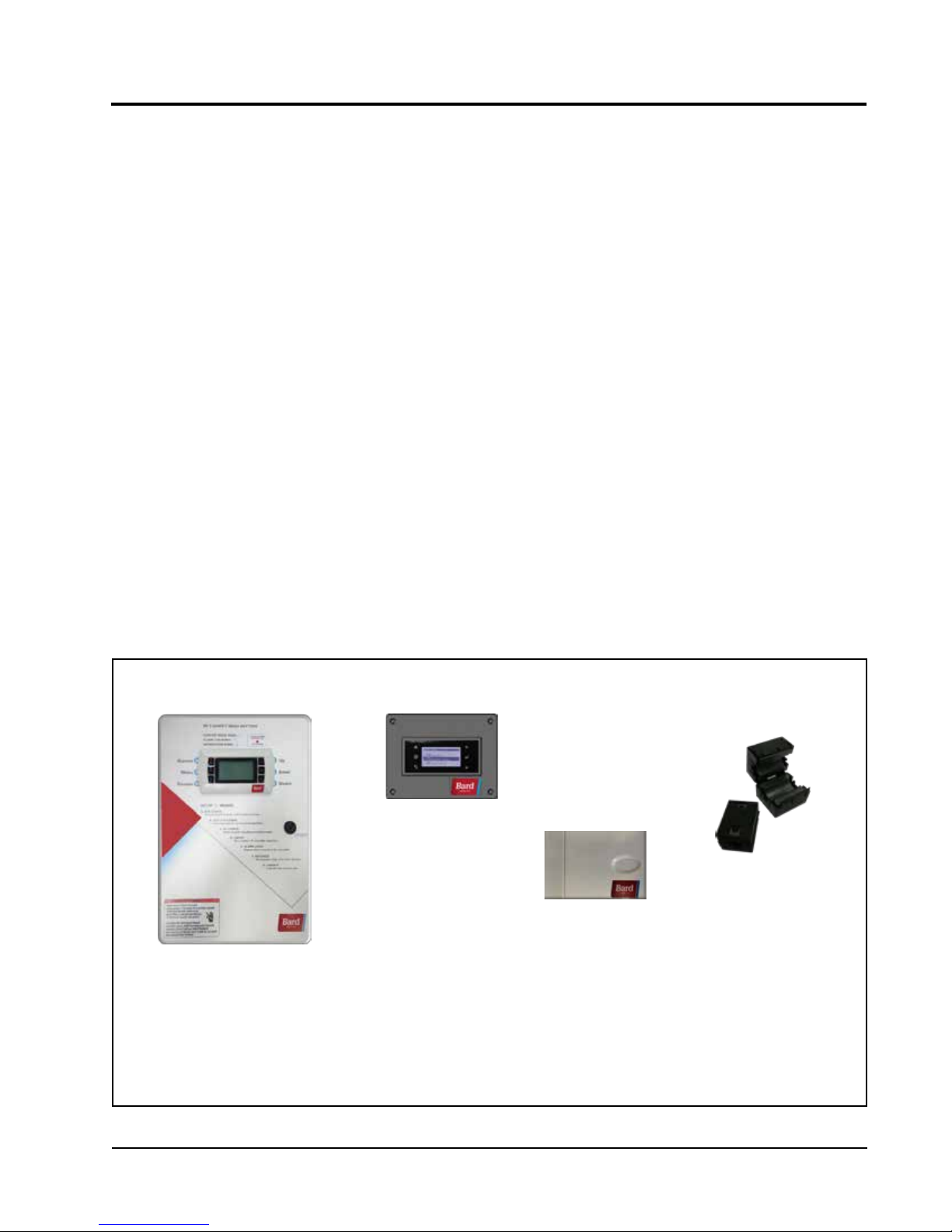
The
Controller
LV1000 controller and accessories included shown
below.
General
The equipment covered in this manual is to be installed
by trained, experienced service and installation
technicians.
The refrigerant system is completely assembled and
charged. All internal wiring is complete.
The unit is designed for use without duct work. Flanges
are provided for transition from unit to wall grilles. A
field-supplied wall sleeve may be necessary between
the supply and return flanges and grilles.
These instructions explain the recommended method
to install the air cooled self-contained unit and the
electrical wiring connections to the unit.
These instructions and any instructions packaged with
any separate equipment required to make up the entire
air conditioning system should be carefully read before
beginning the installation. Note particularly any tags
and/or labels attached to the equipment.
While these instructions are intended as a general
recommended guide, they do not supersede any national
and/or local codes in any way. Authorities having
jurisdiction should be consulted before the installation
is made. See Additional Publications on page 4 for
information on codes and standards.
LV1000 Series
TEC-EYETM Hand-Held
Diagnostic Tool
Bard P/N 8301-059
LV1000 Series
Programmable Logic
Controller
Remote Temperature/
Humidity Sensor*
(with 35' shielded cable)
Bard P/N 8403-079
* One remote temperature/humidity sensor and 35' of 5-wire shielded cable with drain are included with
the LV1000 controller. Up to two additional remote temperature/humidity sensors can be purchased and
installed. Temperature-only sensors (Bard P/N 8301-058) may be used instead of the additional temperature/
humidity sensors, but will also need to be purchased separately. Temperature-only sensors require fieldsupplied 2-wire shielded cable with drain.
Communication
EMI Filters
Bard P/N 8301-055
Manual 2100-674
Page 3 of 42

Sizing of systems for proposed installation should be
based on heat loss and heat gain calculations made
according to methods of Air Conditioning Contractors of
America (ACCA). The supply flange should be installed
in accordance with the Standards of the National
Fire Protection Association for the Installation of Air
Conditioning and Ventilating Systems of Other Than
Residence Type, NFPA No. 90A, and Residence Type
Warm Air Heating and Air Conditioning Systems, NFPA
No. 90B. Where local regulations are at a variance with
instructions, installer should adhere to local codes.
Shipping Damage
Upon receipt of equipment, the cartons should be
checked for external signs of shipping damage. If
damage is found, the receiving party must contact
the last carrier immediately, preferably in writing,
requesting inspection by the carrier’s agent.
These units must remain in upright position at all
times.
Additional Publications
These publications can help when installing the
furnace. They can usually be found at the local library
or purchased directly from the publisher. Be sure to
consult the current edition of each standard.
ANSI Z535.5 Definitions:
DANGER: Indicate[s] a hazardous situation which, if
not avoided, will result in death or serious injury. The
signal word “DANGER” is to be limited to the most
extreme situations. DANGER [signs] should not be used
for property damage hazards unless personal injury risk
appropriate to these levels is also involved.
WARNING: Indicate[s] a hazardous situation which,
if not avoided, could result in death or serious injury.
WARNING [signs] should not be used for property
damage hazards unless personal injury risk appropriate
to this level is also involved.
CAUTION: Indicate[s] a hazardous situation which, if
not avoided, could result in minor or moderate injury.
CAUTION [signs] without a safety alert symbol may be
used to alert against unsafe practices that can result in
property damage only.
NOTICE: [this header is] preferred to address practices
not related to personal injury. The safety alert symbol
shall not be used with this signal word. As an
alternative to “NOTICE” the word “CAUTION” without
the safety alert symbol may be used to indicate a
message not related to personal injury.
National Electrical Code ...................... ANSI/NFPA 70
Standard for the Installation of Air Conditioning
and Ventilating Systems ...................ANSI/NFPA 90A
Standard for Warm Air Heating
and Air Conditioning Systems ............ANSI/NFPA 90B
Load Calculation for Residential Winter
and Summer Air Conditioning ............. ACCA Manual J
For more information, contact these publishers:
Air Conditioning Contractors of America (ACCA)
1712 New Hampshire Ave. N.W.
Washington, DC 20009
Telephone: (202) 483-9370 Fax: (202) 234-4721
American National Standards Institute (ANSI)
11 West Street, 13th Floor
New York, NY 10036
Telephone: (212) 642-4900 Fax: (212) 302-1286
American Society of Heating, Refrigeration and Air
Conditioning Engineers, Inc. (ASHRAE)
1791 Tullie Circle, N.E.
Atlanta, GA 30329-2305
Telephone: (404) 636-8400 Fax: (404) 321-5478
National Fire Protection Association (NFPA)
Batterymarch Park
P. O. Box 9101
Quincy, MA 02269-9901
Telephone: (800) 344-3555 Fax: (617) 984-7057
Manual 2100-674
Page 4 of 42
!
WARNING
!
WARNING
Electrical shock hazard.
Have a properly trained individual perform
these tasks.
Failure to do so could result in electric shock
or death.
!
WARNING
Fire hazard.
Maintain minimum 1/4" clearance between the
supply ange and combustible materials.
Failure to do so could result in re causing
damage, injury or death.
Heavy item hazard.
Use more than one person to handle unit.
Failure to do so could result in unit damage or
serious injury.
!
CAUTION
Cut hazard.
Wear gloves to avoid contact with sharp
edges.
Failure to do so could result in personal injury.
Manual 2100-674
Page 5 of 42
LIST OF NECESSARY MATERIALS/TOOLS
Additional hardware and miscellaneous supplies are needed for installation. These items are field supplied and must
be sourced before installation. This list also includes tools needed for installation.
List of Materials/Tools
• Personal protective equipment/safety devices/ antistatic wrist straps
• SGR-5W Supply Grille and RGR-5W Return Grille
• Field-fabricated sleeves (if necessary)
• Bottom mounting bracket #113-140 (optional)
• Fasteners sufficient for mounting the units such as
5/16" diameter anchor/lag bolts
• 7/8" diameter washers
• Fasteners appropriate for the shelter wall
construction to attach the controller to the wall
• Commercial grade outdoor silicone sealant
• Miscellaneous hand and power tools and jobsite or
shop materials
• Lifting equipment with the necessary capacity and
rigging to safely move/install the systems
• Water to prime drain traps
• Electrical supplies
- Various size circuit breakers for the shelter AC
breaker box (see Table 3 on page 16)
- High-voltage wire of various gauges
(see Table 3)
- 16 gauge minimum, 14 gauge maximum
power wire to connect controller to shelter
power source
- 5-wire, 18 gauge shielded cable with drain
for remote temperature and humidity sensors
(2-wire, 18 gauge shielded cable with drain for
temperature-only sensors)
- Communication wire: 2-wire, 18 gauge,
shielded with drain
- 18 gauge non-shielded wire for connecting
smoke detector, hydrogen detector and/or
generator, if applicable, to controller
-
- Miscellaneous electrical supplies including
CAT 6 Ethernet cable of field-determined length
(for remote communication, if applicable)
rigid/flexible conduit and fittings, 2" x 4"
junction boxes (one per temperature/humidity
sensor), wire connectors and supports
The following is required and must be sourced prior
to installation of these units.
• One (1) 5A circuit breaker for the shelter DC
power plant (for the controller)
Circuit breakers for Emerson Network Power (ENP)
power plants (used in most telecomm shelters built
today) are available directly through the following
distributors:
• Emerson Network Power: 440.288.1122
• Master Electronics: 888.473.5297 or
www.onlinecomponents.com
Emerson Network Power (ENP) Part Number
• 5A circuit breaker: P/N 101598
Always confirm the application before ordering.
Manual 2100-674
Page 6 of 42
SITE PREPARATION
Model Identification
Identify the specific model using the model
nomenclature information found in Figure 1 and
the model/serial tag found on the unit. See Figure
2 on page 9 for dimensions and critical installation
requirements.
New Shelter Installation vs. Retrofit
Installation
These installation instructions cover both new shelter
installations and retrofit installations. Each installation
FIGURE 1
FUSION-TEC Wall-Mount Unit Model Nomenclature
HR 58 A P A 0Z E P X X X X
UNIT SERIES
MAXIMUM SENSIBLE CAPACITY
58 – 5 Ton 2 Stage Step Capacity
REVISION
A – Revision Level
CONTROL LOGIC AND CLIMATE OPTIONS
0Z – O kW with Circuit Breaker
01 – 1.5 kW with Circuit Breaker
05 – 5 kW with Circuit Breaker
5 – Internal and External Cabinet Component Coating, Coated Evaporator Coil, Coated Condenser Coil
P – Programmable Logic Board
VOLTS & PHASE
A – 230/208/60/1
B – 230/208/60/3
MZ – O kW with Circuit Breaker and Inverter
M1 – 1.5 kW with Circuit Breaker and Inverter
M5 – 5 kW with Circuit Breaker and Inverter
E – Factory-Installed Economizer (All Units)
P – MERV8 Disposable Pleated Filter
X – Copper/Aluminum Evaporator Coil, Copper/Aluminum Condenser Coil
4 – Condenser Section Component Coating, Coated Evaporator Coil, Coated Condenser Coil
X – Standard accessories including airflow sensor, dirty filter sensor, pressure transducers, crankcase heater
S – All standard accessories plus additional Bard Guard
is unique and may require special accommodations and
modifications. Although Bard Manufacturing follows a
long-established tradition of manufacturing equipment
using industry standard dimensions for building
penetration, it is occasionally necessary to move or
enlarge supply and return openings when replacing
non-standardized equipment in a retrofit application.
IMPORTANT: All retrofit installations require any
existing supply and return grilles be removed and
discarded. This is a counterflow unit and requires
specified grilles to ensure proper system performance.
ELECTRIC HEAT
VENT PACKAGE
FILTER
COLOR AND CABINET FINISH
X – Beige Baked Enamel Finish
1 – White Baked Enamel Finish
4 – Buckeye Gray Baked Enamel Finish
5 – Desert Brown Baked Enamel Finish
8 – Dark Bronze Baked Enamel Finish
PLACEHOLDER
X – Future Use
COIL AND UNIT COATING OPTIONS
1 – Coated Evaporator Coil
3 – Coated Evaporator Coil, Coated Condenser Coil
2 – Coated Condenser Coil
ACCESSORIES AND CONTROLS OPTIONS
TM
security features and security frame
Manual 2100-674
Page 7 of 42
Minimum Clearance
Counter flow wall-mount air conditioner models have
a removable lower front service panel that allows
access to the control panel, blower, compressor, circuit
breakers and heat strip. There is a hinged access panel
on both sides for filter change and evaporator coil
service.
The upper side panel is removable to allow access
to condenser fan, condenser coil and filter drier. The
design allows for installations to place units within
close proximity without complicating maintenance and
repair.
To maintain full serviceability, side-by-side installations
require 15" of clearance between units.
The condenser discharge air exits through the top
of the unit. Although this reduces the potential for
recirculation, it is still critical to system performance
that any obstruction, shrubbery or structure adhere to
minimum clearances listed (see Table 1).
For overhangs not exceeding 12" from exterior wall,
minimum allowable clearance from top of unit
to bottom of overhang should be no less than 5".
For overhangs greater than 12" from exterior wall,
minimum allowable clearance from top of unit to
bottom of overhang should be no less than 10".
Clearance to Combustibles
The unit itself is suitable for 0" clearance, but the
supply air flange requires a minimum of 1/4" clearance
to combustible material. However, it is generally
recommended that a 1" clearance is used for ease of
installation and maintaining the required clearance
to combustible material. See Figure 8 on page 13 for
details on opening sizes.
!
WARNING
Fire hazard.
Maintain minimum 1/4" clearance between the
supply ange and combustible materials.
Failure to do so could result in re causing
damage, injury or death.
TABLE 1
Clearance Required for Service Access and Adequate Condenser Airflow
Model Side(s)
HR58 15" 5" 10"
Discharge (Top)
Overhang 12" or less
Discharge (Top)
Overhang
Exceeding 12"
TABLE 2
Minimum Clearances Required to Combustible Materials
Model Supply Air Flange Cabinet
HR58 1/4" 0"
Intake (Base) Front of Unit
15" from
Snowline
36" 24"
Shelter
Equipment from
Supply Grille
Manual 2100-674
Page 8 of 42
2° Pitch
Rain Hood
Access Panel
Condenser
Built In
Service Port
Cover
K
N
D
7.125
I
1.500
C
A
H
J
L
M
Side Wall
Mounting
Brackets
(Built In)
Top Rain
Flashing
Shipping
Location
Q
R
E
B
B
.500
P
Q
Q
Q
O
MIS-3894
HR58
UNIT
Side View
Front View
Electric
Heat
Back View
F
W
G
Circuit
Breaker
Disconnect
Filter
Access
Panel
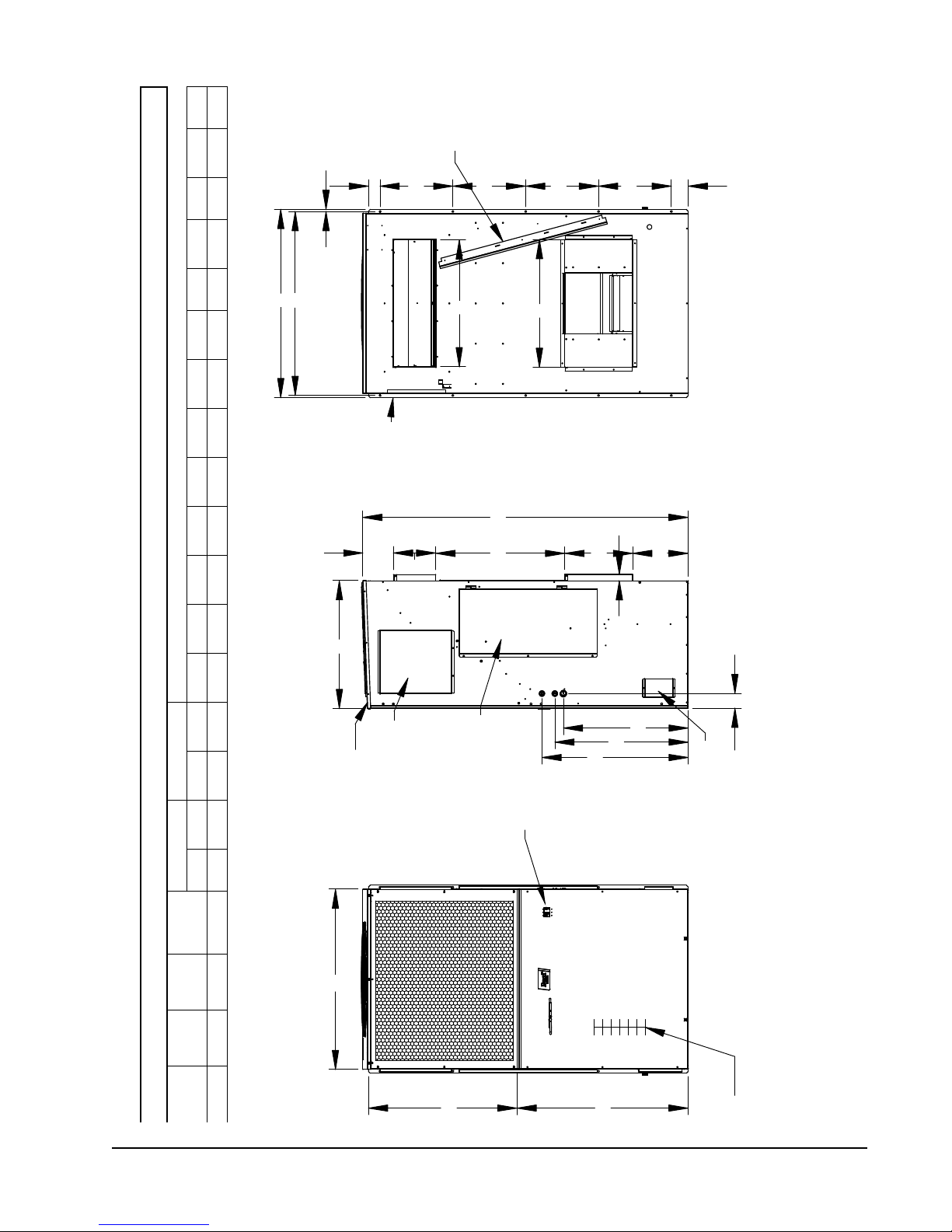
FIGURE 2
A B C B E F G I J K L M N O P Q R
(H)
(D)
(W)
Return Supply
Height
Depth
Width
HR58 42.00 30.00 76.00 9.88 29.88 14.25 29.88 44.00 40.00 34.13 30.00 29.13 13.00 31.13 34.13 3.50 43.00 2.69 17.00 3.88
Model
Dimensions of Basic Unit for Architectural and Installation Requirements (Nominal)
All dimensions are in inches. Dimensional drawings are not to scale.
Sizes:
.875" (2)
Knockout
1.093" (1)
Manual 2100-674
Page 9 of 42
WALL-MOUNT UNIT MOUNTING
Mounting the Units
!
WARNING
Heavy item hazard.
Use more than one person to handle unit.
Failure to do so could result in unit damage or
serious injury.
NOTE: It may be best to spot some electrical knockouts
(such as those located on the sides of the
wall-mount unit) before units are mounted and
access is unavailable or limited (see Figure 2 to
locate pre-punched knockouts).
Two holes for the supply and return air openings must
be cut through the wall as shown in Figure 8 on page
13. On wood frame walls, the wall construction must
be strong and rigid enough to carry the weight of the
unit without transmitting any unit vibration. All walls
must be thoroughly inspected to ensure that they are
capable of carrying the weight of the installed unit.
In retrofit (unit replacement) installations, the openings
cut for the original equipment may not line up exactly
with needs of this installation. Modifications may need
to be made, such as increasing or decreasing the size
of the wall cutouts. The existing bolt placement may
not line up in which case the original bolts would need
to be removed or cut away.
These units are secured by full-length mounting
brackets built into the cabinet on each side. An
optional bottom mounting bracket (purchased
separately) is available, but not required.
The unit itself is suitable for 0" clearance, but the
supply air flange requires a minimum of 1/4" clearance
to combustible material. However, it is generally
recommended that a 1" clearance is used for ease of
installation and maintaining the required clearance
to combustible material. See Figure 8 for details on
opening sizes.
IMPORTANT: When removing the shipping pallet from
beneath the wall unit, do not loosen or remove any of
the screws from either side of the unit.
1. Locate and mark lag bolt locations on both sides
and location for optional bottom mounting bracket,
if desired (see Figure 8).
NOTE: Top rain flashing is attached to back of unit
for shipping purposes. Be sure to remove this
flashing before installing unit.
2. If desired, hook top rain flashing under back bend
of top.
3. Position unit in opening and secure with fasteners
sufficient for the application such as 5/16" lag/
anchor bolts; use 7/8" diameter flat washers on
the lag bolts. It is recommended that a bead of
commercial grade outdoor silicone sealant caulk be
placed behind the side mounting flanges.
NOTE: Opening and removing the filter access door
from each side may make fastening unit to wall
easier.
4. Secure optional rain flashing to wall and caulk
around entire unit (see Figure 8).
5. For additional mounting rigidity, the return air
and supply air frames or collars can be drilled
and screwed or welded to the structural wall itself
(depending upon wall construction). Be sure to
observe required clearance if combustible wall.
6. Four plastic drain hoses extend from the condenser
and evaporator drain pans. The drain hoses are
secured to fittings mounted to the unit base.
NOTE: At the time of installation, Bard highly
recommends prefilling of the traps on both of
the indoor drain pan hoses to ensure proper unit
drainage at start. The water traps can easily
be seen with the front service panel removed.
To fill traps, pour water into both sides of
evaporator drain pan until the drain hoses are
visibly full (see Figure 3).
A unique feature of the FUSION-TEC is the ability to
hang the front service panel on the unit in a position
that allows full access to the control panel (see
Figure 4) while the unit remains fully functional for
troubleshooting and testing. To do this, remove the
panel and hook top lip of panel into bottom channel
of control panel. For added front panel stability, use
several of the screws that were removed to temporarily
connect the panel to the unit.
Manual 2100-674
Page 10 of 42
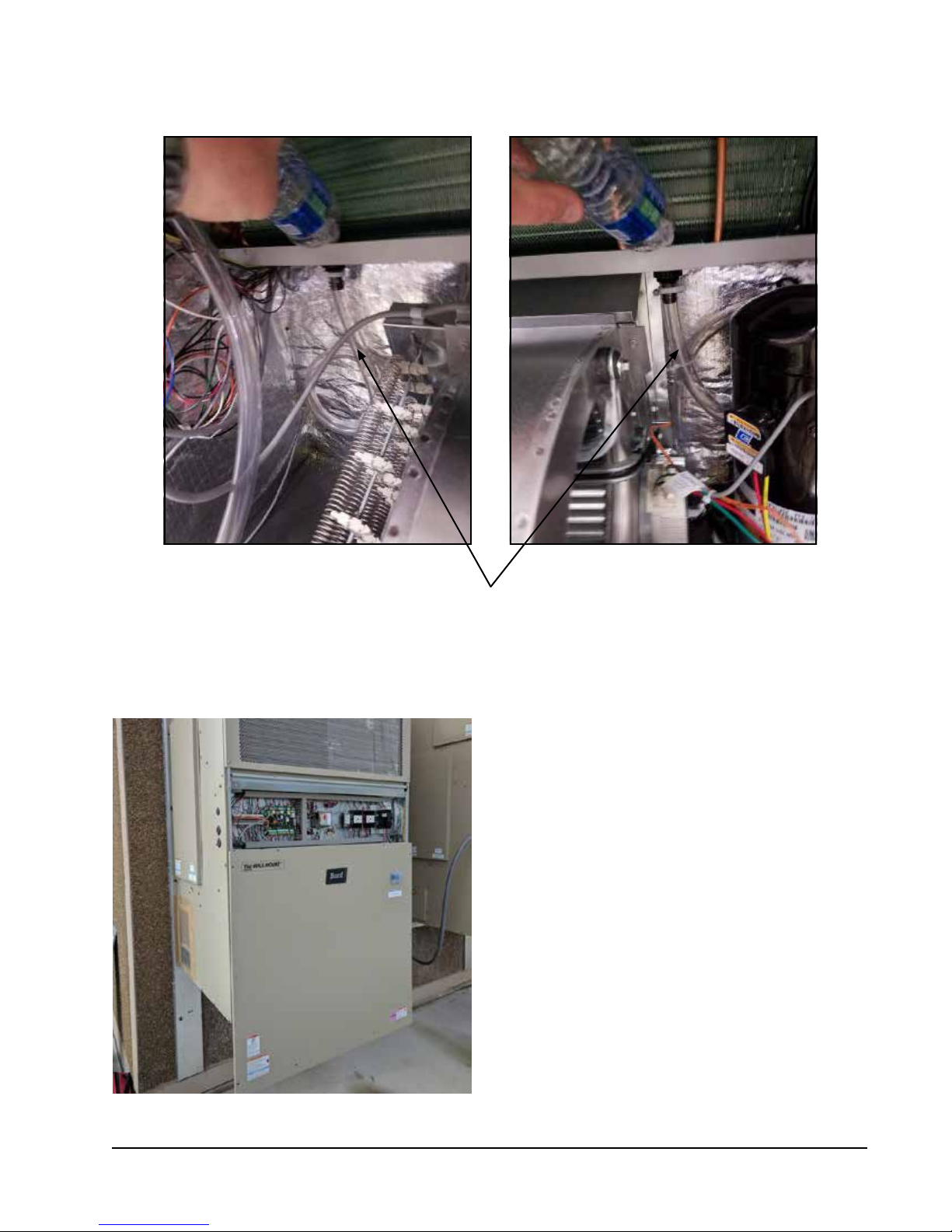
FIGURE 3
Prefilling Traps on Indoor Drain Pan Hoses
Evaporator Drain Pan Left Side Drain Hose Evaporator Drain Pan Right Right Drain Hose
Pour water into evaporator drain pan directly above left and right drain
fittings until coiled drain tubes in blower section are visibly full.
FIGURE 4
Hanging Front Access Panel to Allow
Access to Control Panel
Manual 2100-674
Page 11 of 42
Supply Air Grill Installation
Bard model SGR-5W grille is custom designed for
utilization with Bard wall-mount unit HR58AP for
optimizing the air flow pattern and distribution to
minimize recirculation issues, and optimizing airflow
patterns within the shelter. It is engineered to ensure
that the distributed air is forced in a downward and
outward direction to eliminate obstructions and such
from causing the distributed air from stratifying close
to the unit and getting drawn back into the return air
opening. With the optimized air pattern, the shelter
should experience distributed air at the opposite end of
the room.
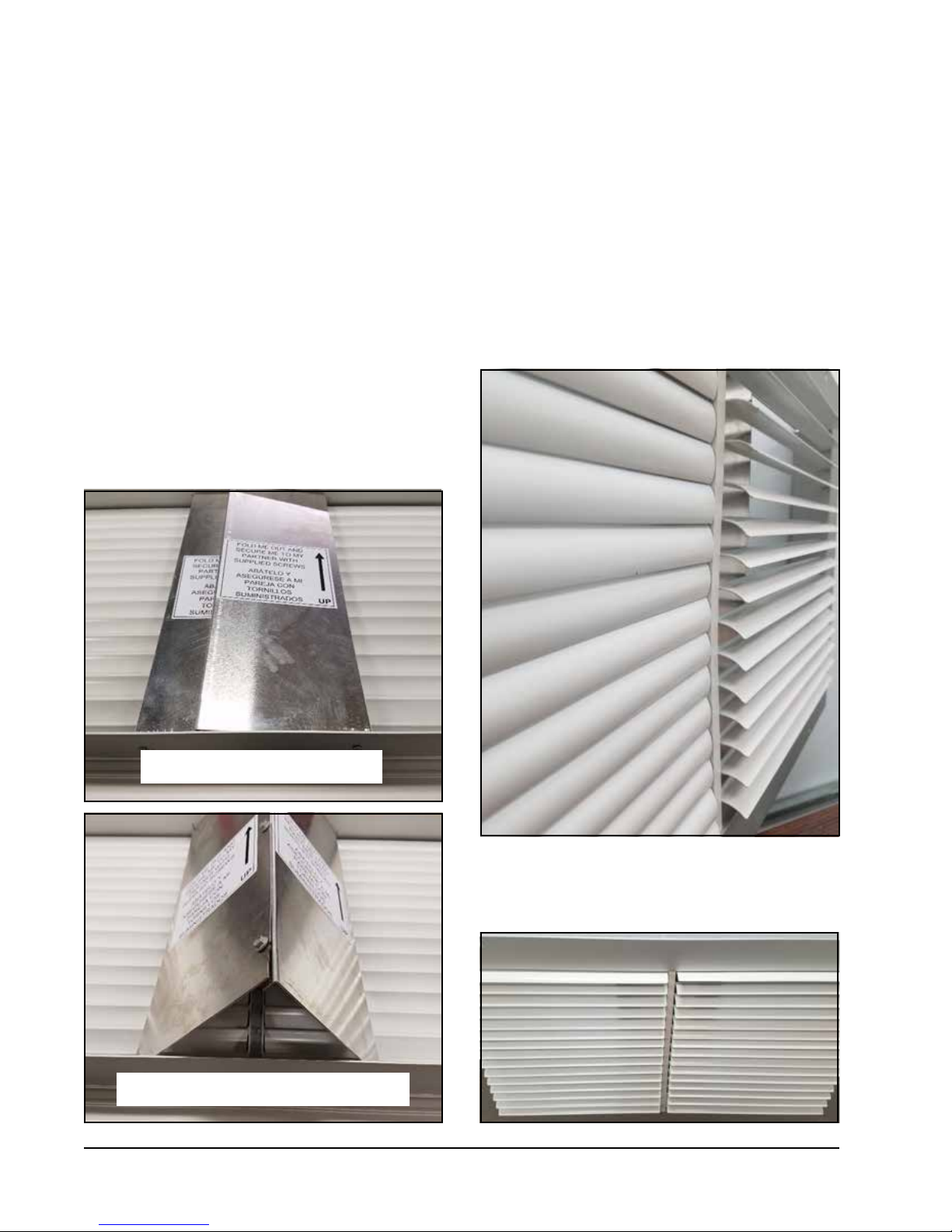
To accomplish this, the grille has two special features:
1. The grille has a specialty fold-out diverter on
the backside of the grille that directs the supply
airflow in an outward pattern, thereby eliminating
the potential for the obstruction of supply air if
FIGURE 5
Fold-Out Diverter
equipment would be directly mounted in front of
the unit. The rear deflectors must be folded out and
secured by the installer with the supplied screws
(see Figure 5).
2. The grille is also equipped with downward curved
diverter blades to ensure a smooth and efficient
means of directing the air pattern in a downward
pattern, and away from being drawn back into
the return air opening. The curved diverter blades
are shipped in the flat position and need to be
folded out to between 75-90° (best tuned to each
individual structure). See Figures 6 and 7.
FIGURE 6
Downward Curved Diverter Blades
Rear deflectors as shipped
Rear deflectors raised and secured together
Manual 2100-674
Page 12 of 42
Diverter blades as shipped (left), and after raising (right)
FIGURE 7
View of Installed Grille (as seen from above)
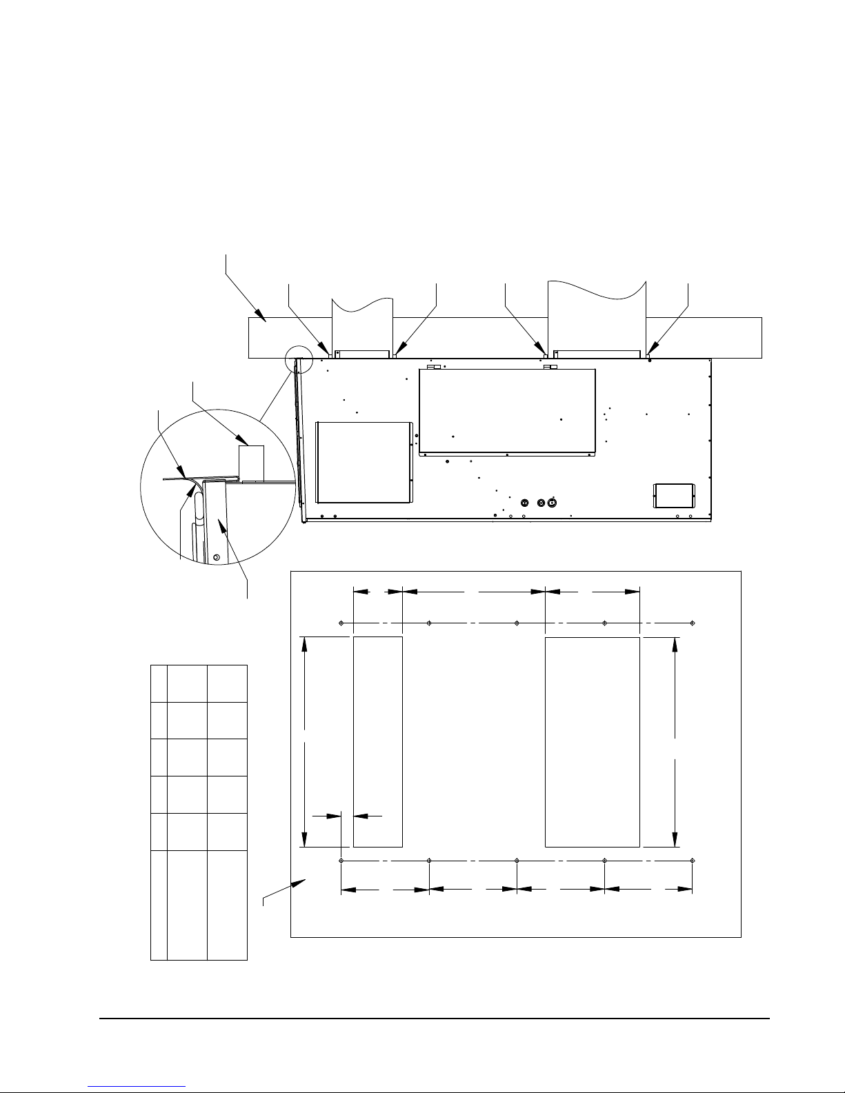
MIS-3898
Wall Structure
During Installation
Foam Air Seal To Support Rain Flashing
Rain Flashing
Supplied
FIGURE 8
Mounting Instructions
Entire Length Of Top
Of Calking Along
Seal With Bead
Foam Seal
Foam Seal
Air
Return
Foam Seal
Supply Air
Opening
Foam Seal
NOTES:
IT IS RECOMMENDED THAT A BEAD OF
SILICONE CAULKING BE PLACED BEHIND
THE SIDE MOUNTING FLANGES AND UNDER
TOP FLASHING AT TIME OF INSTALLATION
Right Side View
"
B
E
16.25
Top Of Unit
A B C D E
32 12 5 1/2 2 29
30 1/2 10 1/2 6 1/4 2 3/4 29 3/4
WALL
MATERIALS
COMBUSTIBLE MATERIALS
FROM COMBUSTIBLE
CLEARANCE FROM
MAINTAIN 1/4" MIN.
REQUIRED DIMENSIONS TO
MAINTAIN 1" MIN. CLEARANCE
REQUIRED DIMENSIONS TO
A
A
Return Air Opening
Supply Air Opening
D
Wall Opening and Hole Location View
17"
17"
17"
17"
Manual 2100-674
Page 13 of 42
 Loading...