

Fusion PowerPlant PP?CM40, PowerPlant PP?CM65, PowerPlant PP?CM525, PowerPlant PP?CMST1 User Manual
Page 1

POWERPLANT
COMPONENT SPEAKER MODELS
PP−CM40, PP−CM525, PP−CM65, PP−CMST1
Page 2

2
FUSION CULTURE
There’s no point doing something if no one notices. We’ve always believed
the way to make things happen is by getting noticed. From our product, to our
demo cars to our events, FUSION is about making some noise.
And now you’re about to. Step out of the shadows. Announce you’ve
arrived in a world where the old limits are left behind. Where technology is
creatively combined with the latest in product innovation. Where new levels
of entertainment are delivered with outstanding performance and quality. Our
development team evolve distinctively different products; subwoofers, amplifiers,
speakers and peripherals that redefine what can be done in car audio.
Leave the old behind and push the limits of what can be achieved in car audio.
Make some noise.
For more information about FUSION Car Audio visit our website at www.fusioncaraudio.com
or email technical@fusionelectronics.co.nz
POWERPLANT
Explore the limits of car audio and PowerPlant will get you there. Fusion PowerPlant delivers
accurate clear sound reproduction with real power. Push sound further than it’s gone before,
confident that PowerPlant products have been engineered, designed and manufactured to
ensure consistent and reliable performance
To optimise your Fusion experience, we recommend you have your FUSION product installed by
an Authorised FUSION Dealer. Please read the warranty policy, keep your purchase receipt and
original packaging.
If after reading this manual you still have questions regarding this product, please contact
Technical Customer Services via email technical@fusionelectronics.co.nz
Page 3

3
RECORD YOUR PRODUCT DETAILS HERE:
MODEL NUMBER _______________________________ DATE OF PURCHASE______________________
AFFIX RECEIPT HERE
WARNING! Audio Systems can produce sound levels over 1
35dB. Continuous exposure to sound
pressure levels over 100dB may cause permanent hearing loss!
Please watch for emergency vehicles as warning signals may not be heard. USE COMMON SENSE!
TABLE OF CONTENTS
• COMPONENT SPEAKER FEATURES. . . . . . . . . . . . . . . . . . . . . . . . . . . . . pg 4
• SPEAKER THEILE/SMALL PARAMETERS . . . . . . . . . . . . . . . . . . . . . . . . .pg 4
• SPEAKER DIMENSIONS PP-CM40 . . . . . . . . . . . . . . . . . . . . . . . . . . . . . .pg 5
•
SPEAKER DIMENSIONS PP-CM525 . . . . . . . . . . . . . . . . . . . . . . . . . . . . .pg 7
• SPEAKER DIMENSIONS PP-CM65 . . . . . . . . . . . . . . . . . . . . . . . . . . . . . .pg 9
• SPEAKER DIMENSIONS PP-CMSTI . . . . . . . . . . . . . . . . . . . . . . . . . . . . .pg 11
• INSTALLATION . . . . . . . . . . . . . . . . . . . . . . . . . . . . . . . . . . . . . . . . . . . .p
g 13
• WIRING . . . . . . . . . . . . . . . . . . . . . . . . . . . . . . . . . . . . . . . . . . . . . . . . . .pg 14
• WOOFER AND MIDRANGE INSTALLATION. . . . . . . . . . . . . . . . . . . . . . . .pg 15
• TWEETER INSTALLATION . . . . . . . . . . . . . . . . . . . . . . . . . . . . . . . . . . . .pg 16
• X-OVER INSTALLATION . . . . . . . . . . . . . . . . . . . . . . . . . . . . . . . . . . . . . .pg 17
•
WIRING DIAGRAM 2-WAY X-OVER . . . . . . . . . . . . . . . . . . . . . . . . . . . . . .pg 18
•
WIRING DIAGRAM 3-WAY X-OVER . . . . . . . . . . . . . . . . . . . . . . . . . . . . . .pg 18
• TECH TIPS . . . . . . . . . . . . . . . . . . . . . . . . . . . . . . . . . . . . . . . . . . . . . . .pg 19
• TROUBLE SHOOTING . . . . . . . . . . . . . . . . . . . . . . . . . . . . . . . . . . . . . . .p
g 20
Page 4

4
COMPONENT SPEAKER FEATURES
PowerPlant Component Speaker Systems feature an industrial cast basket with a protective
finish, green top and bottom plate and a light-weight polypropylene cone complimented by a
soft dome tweeter. The PowerPlant Component Speaker Systems provide style and great sound
reproduction for the car audio specialist.
Component Parameters PP-CM40 PP-CM525 PP-CM65 PP-CMST1
Max Power Rating (Watts)
1
20 150 180 180
Rms Power Rating (Watts)
40 50 60 60
Compliance (Cms)
50
3.3 722.1 676.3 676.3
Cone Area (Sd)
5.67 8.99 1
3.68 13.68
D.C.coil Resistance (Re)
3
.3 3.3 3.3 3.3
Electrical Q (Qes)
0.89 0.61 0.7
3 0.73
Force Factor (Bl)
3
.57 4.2 4.48 4.48
Free Air Resonance (Fs)
94 67 55 55
Frequency Response
65Hz –
21kHz 57Hz – 21kHz 52Hz – 21kHz 52Hz – 21kHz
Impedance (Nominal)
4 4 4 4
Mechanical Excursion
8 9 1
2 12
Mechanical Q (Qms)
5.4 7.97 7.04 7.04
Sensitivity: (dB) (1w/1m)
88 91 91 91
Total Loudspeaker Q (Qts)
0.77 0.57 0.66 0.66
Magnet Structure
7.
3 10.9 1
2.6 12.6
SPEAKER THEILE/SMALL PARAMETERS
X-Over
2 Way Passive Butterworth X-Over Network
12dB/Octave
Adjustable 3 point Tweeter level
High Pass: 3.0 kHz
Low Pass: 4.5 kHz
Page 5
5
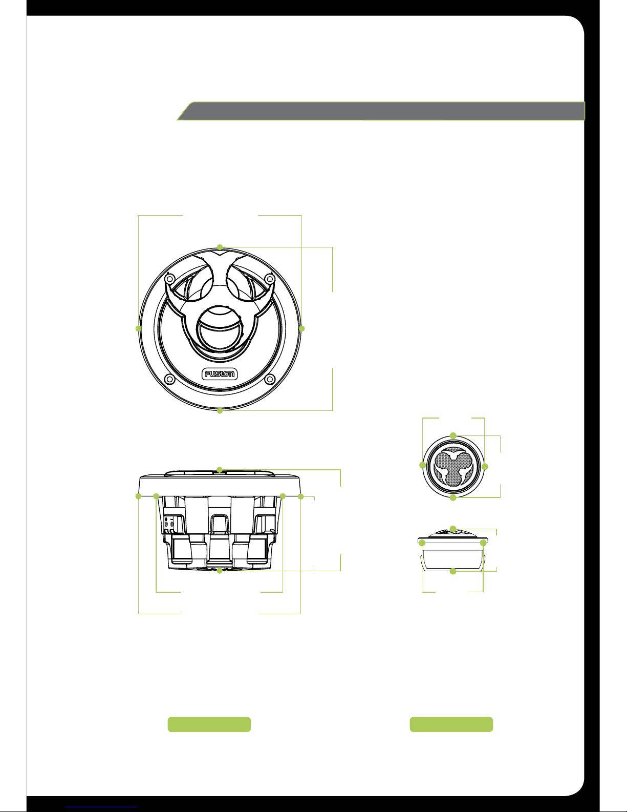
TWEETER
WOOFER
SPEAKER
PP-CM40
DIMENSIONS
128mm (5 -1/16")
128mm (5 -1/16")
79mm (3-1/8")
59mm (2-5/16")
128mm (5 -1/16")
100mm (3 -15/16")
51mm
(2")
51mm
(2")
51mm
(2")
32mm
(1-1/4")
Page 6
6
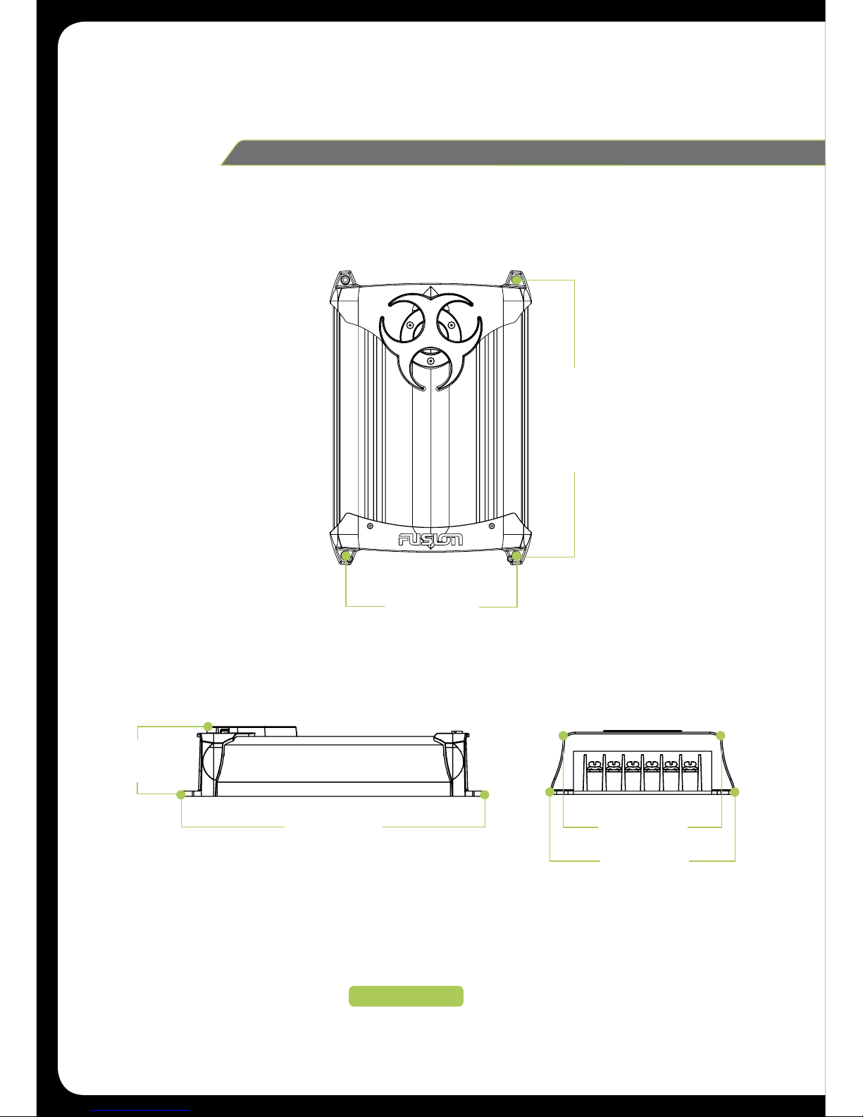
X-OVER
X-OVER
PP-CM40
DIMENSIONS
92mm (3-5/8")
IN+ IN- W+ W- T+ T-
92mm (3-5/8")
107mm (4-1/4")
175mm (6-7/8")
162mm (6-3/8")
40mm
(1- 9/16")
Page 7
7
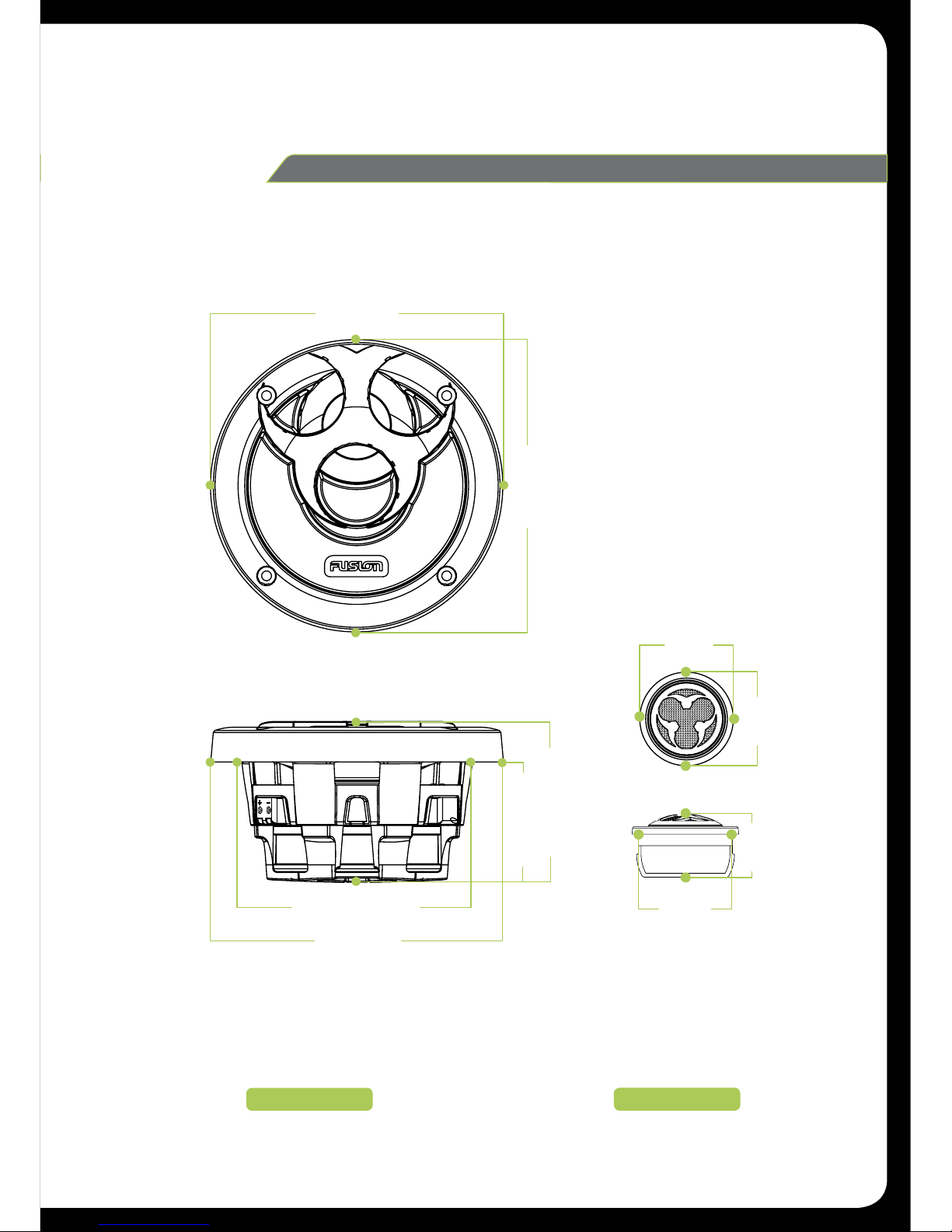
SPEAKER
PP-CM525
DIMENSIONS
TWEETER
WOOFER
152mm (6")
152mm (6")
84mm (3-5/16")
63mm (2-1/2")
152mm (6")
122mm (4-13/16")
51mm
(2")
51mm
(2")
51mm
(2")
32mm
(1-1/4")
Page 8

8
X-OVER
PP-CM525
DIMENSIONS
X-OVER
92mm (3-5/8")
IN+ IN- W+ W- T+ T-
92mm (3-5/8")
107mm (4-1/4")
175mm (6-7/8")
162mm (6-3/8")
40mm
(1- 9/16")
Page 9

9
SPEAKER
PP-CM65
DIMENSIONS
TWEETER
WOOFER
176mm (6-15/16")
176mm (6-15/16")
89mm (3-1/2")
67mm (2-5/8")
146mm (5-3/4")
176mm (6-15/16")
51mm
(2")
51mm
(2")
51mm
(2")
32mm
(1-1/4")
Page 10

10
X-0VER
PP-CM65
DIMENSIONS
X-OVER
92mm (3-5/8")
IN+ IN- W+ W- T+ T-
92mm (3-5/8")
107mm (4-1/4")
175mm (6-7/8")
162mm (6-3/8")
40mm
(1- 9/16")
Page 11

11
SPEAKER
PP-CMST1
DIMENSIONS
TWEETER
WOOFER
176mm (6-15/16")
176mm (6-15/16")
89mm (3-1/2")
67mm (2-5/8")
146mm (5-3/4")
176mm (6-15/16")
51mm
(2")
51mm
(2")
51mm
(2")
32mm
(1-1/4")
Page 12

12
SPEAKER & X-OVER
PP-CMST1
DIMENSIONS
WOOFER
X-OVER
128mm (5 -1/16")
128mm (5 -1/16")
79mm (3-1/8")
59mm (2-5/16")
128mm (5 -1/16")
100mm (3 -15/16")
51mm
(2")
51mm
(2")
51mm
(2")
32mm
(1-1/4")
92mm (3–5/8")
107mm (4–1/4")
92mm (3-5/8")
175mm (6-7/8")
162mm (6-3/8")
40mm
(1-9/16")
IN+ IN- W+ W- M+ M- T+ T-
Page 13

13
INSTALLATION
Before any wiring and installation is performed, FUSION recommends you first plan the complete
installation. Look at wiring routing, speaker location and fitment. Please re-check the installation
at completion.
A front stage and stereo image can be achieved by proper speaker placement. Speakers need to
be positioned on an axis with the listener. Ideally speakers should be situated in locations where
the sound produced is directed to the occupants of the vehicle.
In some circumstances modification to the speaker location may be required. FUSION
recommends a location with sufficient air volume for the speaker to work within its frequency
range. If the air volume is too small there could be lost low frequency notes. FUSION speakers
are designed for optimal sound reproduction across the full audible spectrum – the human ear is
most sensitive to amplitude, pitch, clarity and linearity in the
375Hz to 3 Khz bandwidth.
INSTALLATION WARNING
1: Ensure the vehicle 12 volt lead is removed from the battery before any equipment is
connected.
2:
Investigate the vehicles gas tanks, brake lines and electrical wiring locations before you begin
installation.
3:
Attach the product securely to the vehicle to prevent damage in the event of an accident.
4:
Ensure all wiring is protected to avoid damage or pinching of the cables.
Page 14

14
WIRING
Before any connection is made to the amplifier or source unit, make sure that you turn the audio
system off. Failure to do so could result in either the stock system or new FUSION product
being damaged. FUSION will not warranty damaged speakers due to incorrect installation.
When wiring the FUSION speakers, ensure that the wires are away from sharp objects and that
rubber grommets and insulated bungs are used when wiring through door jams and any other
steel panels. FUSION recommends using the supplied speaker wire for installation. Do not use
wire thinner than the specific wire supplied.
Ensure that when connecting the wires to the speakers and audio system, the terminals and
connections are protected from the vehicles chassis and shorting to each other. If the wires short
together or touch the vehicle chassis, the audio system could be damaged.
When wiring the source and FUSION speakers, ensure you keep the polarity correct. To
successfully do this, wire the positive speaker output from the source unit or amplifier to the
positive of the speaker in the desired location. Do the same with the negative. If you follow this
step then the audio system will be in phase. The result of an out of phase system is lack of bass,
as the left and right, front and rear speakers are opposing audio signals and cancellation occurs.
Page 15

15
1: Check clearance around the mounting area before
installation ensuring that the area is free from
obstruction and there is adequate depth for the
woofer.
2: Using the supplied mounting template, mark the
correct diameter on the mounting surface.
3: Use a suitable cutting tool to remove the marked
surface and drill four holes for the screws to pass
through.
4: Ensure correct polarity before connecting the
speaker terminals to the source unit or amplifier
using the speaker cable provided.
5: Insert speaker and grill into the speaker mounting
hole and affix the speaker with the screws and
mounting hardware provided.
Note: If a stock location is used, the grill frame will
not be required.
WOOFER & MIDRANGE INSTALLATION
Note: Ensure the audio system is off during installation of FUSION product. Once the installation
is complete FUSION recommends that you turn the volume of the source unit up slowly to prevent
damaging the speakers. Please recheck the complete installation prior to turning the audio system
on.
Page 16

16
TWEETER INSTALLATION
TWEETER (surface/angle mount)
FUSION offers three choices of mounting styles
to accommodate the varying requirements for
on and off axis mounting positions. The most
important goal for tweeter placement is the
need to keep an un-obstructed path on axis to
approximately 4" below the rear vision mirror.
The reason for this is to enhance the perception
of centre image. When mounting, make sure
there is no wiring behind the mounting surface,
use the tweeter mount that enables the best
sound focus and use this as the template for
drilling the mounting holes. If using the double
sided adhesive pad, clean all surfaces down
with isopropyl alcohol or some other residue free
cleaner and stick the tweeter down. Ensure it
does not obstruct either car door from closing.
Run the wiring back to the x-over.
TWEETER (flush mount)
First check that the tweeter can be flush mounted
into the surface you have chosen, especially
with regards to depth. Mark out a 51mm hole
and cut this out. Having a hole saw will greatly
improve the tidiness and the integrity of the hole.
Assemble the rear mount with the spring clamp
and press through from the rear of the mounting
surface, then bayonet the front plate and the
rear mount together as shown in the flush mount
illustration. Run the wiring back to the x-over.
SELECTABLE TWEETER GAIN SWITCH
The FUSION x-over comes with a selectable
gain switch. This allows the tweeter volume to be
adjusted +/-
3 dB (half or double volume).
Page 17

17
X-OVER INSTALLATION
X-OVER INSTALLATION
1:
FUSION x-overs are manufactured specifically for use with the FUSION full range component
system. Use of any other crossover may result in damage to one or more of the components.
2:
The x-over is designed for installation under the vehicle dash, under the rear parcel shelf or in
the trunk of the vehicle. They should not be located where they are subject to moisture, such
as a leaky door. If possible locate the x-overs closer to the speakers than the amplifier.
3:
Remove the x-over bottom plate to gain access to the connecting screws (do not attempt to
pry the bottom plate off).
4:
Use the x-over to mark the mounting holes. Make sure there is sufficient clearance on the
other side of the mounting surface and that the mounting surface is perfectly flat to avoid
damage to the x-over.
5:
Drill four 1/8" pilot holes for the screws and wire the x-overs.
6:
Cut the pre-run speaker cable to the correct length. Connect the cable to the x-over, ensure
the correct polarity.
7:
Refit the x-over bottom plate and screw into position.
8:
Adjust the tweeter level at the opposite end of the wire connection block, –3, 0, +3dB.
INSTALLATION TIPS
1:
To avoid confusion, mark the opposite ends of each cable in the same manner, but mark the
second cable differently from the first. (A good idea is to mark the + and – ends of the left
tweeter cable with one piece of electrical tape and both the + and – ends of the left woofer
have two pieces of electrical tape).
2:
For doors, route the cabling through the factory cable harnesses or existing holes, where
possible. If drilling holes, file the burred edges and install rubber grommets to protect the
wires against abrasion. For the rear of the vehicle, route cables along the door sills, lifting and
replacing the carpet as required. You may have to remove the rear seat (depending on your
vehicle configuration) to route cables to the rear.
Page 18

18
+
+
2-WAY X-OVER
PP-CM40, PP-CM525, PP-CM65
WIRING DIAGRAM
3-WAY X-OVER
PP-CMST1
WIRING DIAGRAM
Page 19

19
TECH TIPS
In order to achieve accurate stereo imaging in your vehicle some basic principles should be
applied. Designing a system around the principles of front stage and rear fill will enable the
listener to perceive a stereo image in the front of them. The rear fill is the result of sound
reflecting off the rear windshield and other surfaces which then travels to the listener.
A front stage image can be achieved by proper speaker placement. Speakers need to be
positioned on an axis with the listener, which means speakers in doors may not always be the
best location since you are relying on how well their off axis dispersion is.
It must be understood that one speaker alone cannot reproduce the humans ear’s audible
bandwidth of
20Hz-20kHz. There is a critical bandwidth which is a three octave range centred
around 1kHz. This bandwidth starts at 375Hz. This is where the human ear is most sensitive to
amplitude, pitch, clarity and linearity.
Basic tools required: In any installation these basic tools may be required. For custom type
installations, additional tools maybe necessary.
• Electric drill
• Flat blade screwdrivers
• Crimping tool
• Electrical tape
• Phillips screwdriver
• Wire strippers
• Utility knife, sabre saw, jigsaw, nibbler
• Silicon sealant
Page 20

20
TROUBLE SHOOTING
Before you contact your FUSION dealer or service centre, FUSION requires that you do some
simple trouble shooting to help to diagnose the problem.
If the FUSION speaker has been installed by a professional installation company, then
we recommend that you return to the company so the technician can assess the problem
and advise.
No sound:
Check all connections from the source unit and amplifier to the speaker, tweeter and x-over
terminals.
System lacks in bass:
1:
Check the connections from the source unit/amplifier to the x-over and speakers. Ensure
the positive wire from the source is connected to the positive of the x-over and speaker.
2:
Ensure the speakers are mounted firmly to the mounting surface.
System lacks in high frequencies:
1:
Check polarity.
2:
Check tweeter connections on the x-over.
3:
Check the bass/treble control settings on the source unit.
Distorted sound:
1:
Check all wiring.
2:
Check that it is not the surrounding panels of the vehicle rattling. Check connections from
the source to the x-over and speaker.
Page 21

21
NOTES
Page 22

22
NOTES
Page 23

23
YOU CAN HELP PROTECT THE ENVIRONMENT!
Please remember to respect the local regulations:
Hand in the non-working electrical equipment
to an appropriate waste disposal center
PUBLISHED BY FUSION ELECTRONICS LIMITED:
© Copyright
2006 by FUSION Electronics Limited.
All rights reserved. Specifications and design are
subject to change without notice.
NOTES
Page 24

Specifications and design are subject to change without notice.
 Loading...