

Page 1
ENCOUNTER
PERFORMANCE
PERFORMANCE
AMPLIFIER MANUAL
PF-1802 PF-4001D PF-4004
PF-8003D PF-8001D
Page 2
22
Version 2.1
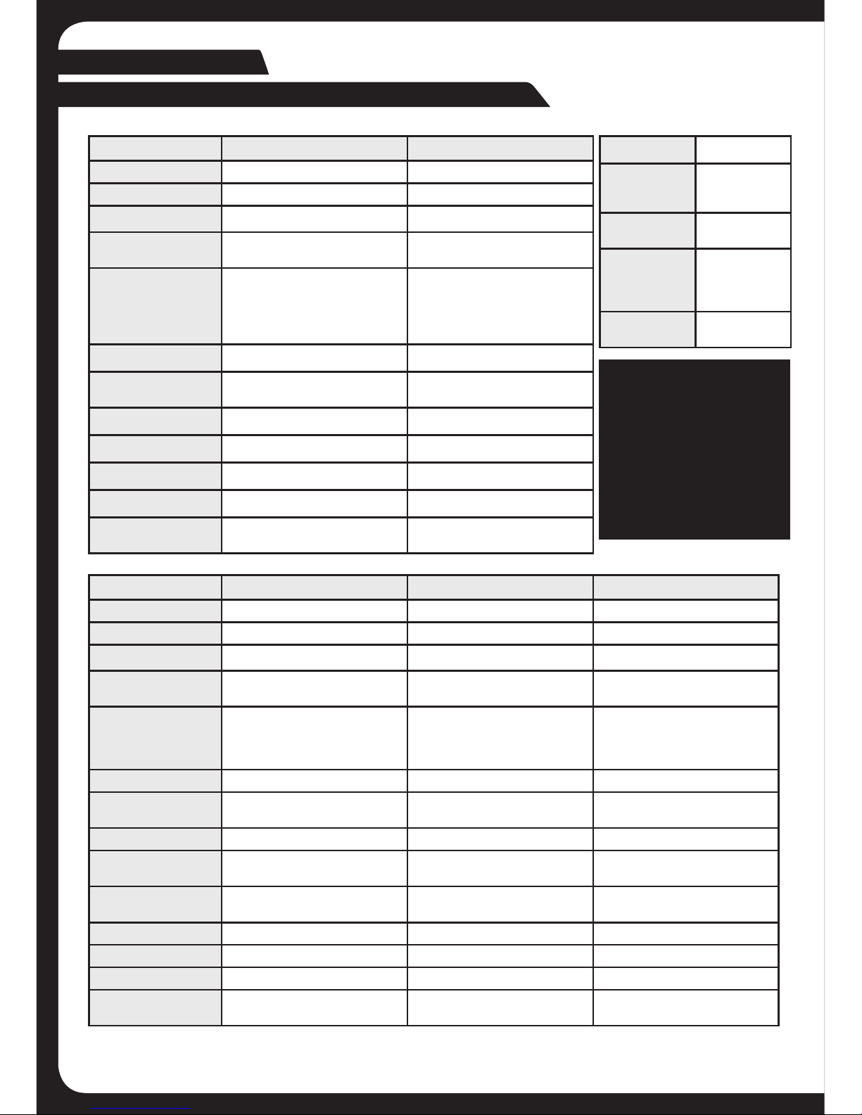
PF-1802 (2 Channel) PF-4004 (4 Channel)
Class Class-AB Class-AB
Power 1200 Watts 2400 Watts
Frequency Response 20Hz - 20kHz 20Hz - 20kHz
Dimensions 246mm (9-11/16”) x 200mm
(7-7/8”) x 51mm (2”)
386mm (15-3/16”) x 200mm
(7-7/8”) x 51mm (2”)
RMS Power Ratings 65W x 2 @ 4 Ohms 1% THD+N
90W x 2 @ 2 Ohms 1% THD+N
180W x 1 @ 4 Ohms Bridged 1%
THD+N
80W x 4 @ 4 Ohms 1% THD+N
100W x 4 @ 2 Ohms 1% THD+N
200W x 2 @ 4 Ohms Bridged 1%
THD+N
Signal to Noise Ratio >50 dB >50 dB
High and Low Pass
Crossover
12dB per Octave 12dB per Octave
Bass Boost @ 45Hz 0 - +18dB N/A
Crossover Range 50Hz – 400Hz 50Hz – 400Hz
Low Level Input Range 0.35 Volts to 10 Volts 0.35 Volts to 10 Volts
High Level Input Range 1 Volt to 30 Volts 1 Volt to 30 Volts
Minimum load
impedance
2 Ohm stereo and 4 Ohm bridged 2 Ohm stereo and 4 Ohm bridged
PF-4001D (Monoblock) PF-8001D (Monoblock) PF-8003D (3 Channel)
Class Class-D Class-D Class-D
Power 1600 Watts 3200 Watts 2400 Watts
Frequency Response 10Hz - 250Hz 10Hz - 250Hz 10Hz - 20kHz
Dimensions 236mm (9-1/4”) x 200mm (7-
7/8”) x 51mm (2”)
306mm (12”) x 200mm (7-7/8”) x
51mm (2”)
306mm (12”) x 200mm (7-7/8”) x
51mm (2”)
RMS Power Ratings 250W x 1 @ 4 Ohms 1% THD
400W x 1 @ 2 Ohms 1% THD
500W x 1 @ 4 Ohms 1% THD
800W x 1 @ 2 Ohms 1% THD
Link Mode (Two PF-8001D)
1600W x 1 @ 4 Ohms 1% THD
Front 90W x 2 @ 4 Ohms
150W x 2 @ 2 Ohms 1% THD+N
Sub 230W x 1 @ 4 Ohms
500W x 1 @ 2 Ohms 1% THD+N
Signal to Noise Ratio >50 dB >50 dB >50 dB
High and Low Pass
Crossover
12dB per Octave 12dB per Octave 12dB per Octave
Subsonic Filter 12dB per Octave 12dB per Octave 12dB per Octave
Low Pass Crossover
Range
50Hz – 250Hz 50Hz – 250Hz 50Hz – 250Hz
Subsonic Crossover
Range
10Hz – 40Hz 10Hz – 40Hz 10Hz – 40Hz
Bass Boost @ 45Hz 0 to +18dB 0 to +18dB 0 to +18dB
Low Level Input Range 0.35 Volts to 10 Volts 0.35 Volts to 10 Volts 0.35 Volts to 10 Volts
High Level Input Range 1 Volt to 30 Volts 1 Volt to 30 Volts 1 Volt to 30 Volts
Minimum load
impedance
2 Ohm 2 Ohm and 4 Ohm in Link mode 2 Ohm
AMPLIFIER SPECIFICATIONS
NOTE:
PERFORMANCE
AMPLIFIER SERIES
HAVE A MINIMUM
LOAD IMPEDANCE
OF
2 OHM PER
CHANNEL
4 OHM BRIDGED
General
Power
Requirements
+12 V DC
(negative
ground)
Operating
Voltage
10.5 – 16V
Minimum
RecommendedPower/Ground
Cable Size
4 Gauge (AWG)
Recommended
inline fuse size
4 Gauge Cable
- 80A
ENGLISH
Page 3
3
AMPLIFIER INSTALLATION
INSTALLATION WARNINGS
1. Ensure the +12V lead is disconnected from the battery before you connect any new
equipment.
2. Ensure that the amplifier mounting location and holes will not interfere with the gas tank,
brake lines or electrical wiring.
3. Ensure the amplifier is securely fastened to the vehicle to prevent the amplifier moving and
causing damage in the event of an accident.
4. Ensure all wiring is protected from sharp objects and from pinching or crushing which
could result in damage to the audio system.
5. Ensure the mounting location has sufficient air flow around the amplifier. If the amplifier is
mounted in an enclosed space a 3” fan with ducting should be used to assist with cooling.
6. Do not mount any amplifier on a subwoofer enclosure as extended exposure to vibration
may cause damage to the amplifier.
7. Ensure you use the minimum recommended gauge wire/cable or larger for all amplifier
connections.
8. Appropriate mounting is very important for prolonged life expectancy of any amplifier.
Select a location that provides protection from moisture. Keep in mind that an amplifier
should never be mounted upside down. Upside down mounting will compromise heat
dissipation through the heat sink and could engage the thermal protection circuit.
CONNECTION
Ensure the audio system is turned off before making any connections to the amplifier,
speakers or source unit. Failure to do so could result in permanent damage to the audio
system.
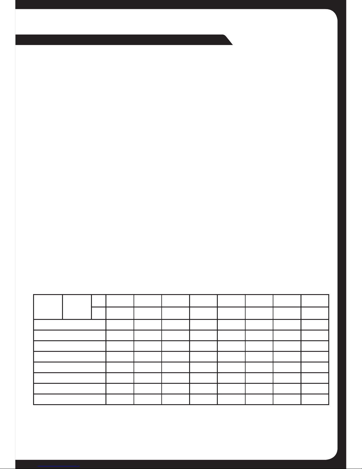
Ensure the correct gauge cable is used for all connections; consult the cable calculator
diagram below for the correct gauge cable for your installation.
TOTAL
AMPS
CABLE
LENGTH
>
M 0 - 1 1 - 2 2 - 3 3 - 4 4 - 5 5 - 6 6 - 7 7 - 9
FT 0- 4 4 - 7 7 - 10 10 - 13 13 - 16 16 - 19 19 - 22 22 - 28
0 - 20 14 12 12 10 10 8 8 8
20 - 35 12 10 8 8 6 6 6 4
35 - 50 10 8 8 6 4 4 4 4
50 - 65 8 8 6 4 4 4 4 2
65 - 85 6 6 4 4 2 2 2 0
85 - 105 6 6 4 2 2 2 2 0
10 5 - 12 5 4 4 4 2 0 0 0 0
125 - 150 2 2 2 0 0 0 0 0
The above chart shows cable gauges to be used, if no less than a 0.5 volt drop is acceptable.
If aluminium wire is used, the gauges should be of an even larger size to compensate. Cable
gauge size calculation takes into account terminal connection resistance.
Page 4
44
1 3
2
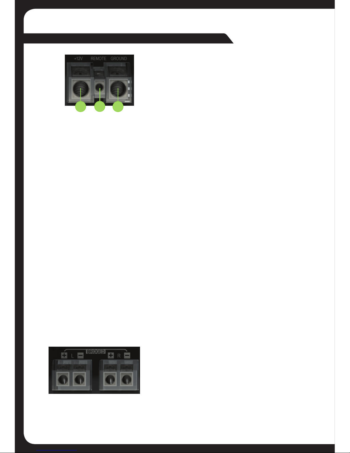
AMPLIFIER CONNECTONS
1. +12V POWER
Ensure ALL other cable connections are
completed before connecting this cable to the
battery. FUSION amplifiers should be connected
directly to the 12v battery terminal using the
appropriate gauge cable. Start at the vehicles
battery and run the cable through to the
amplifier. FUSION recommends the use of rubber
grommets when passing any cable through metal
panels to avoid sharp corners or panels that could
cut through the insulation of the cable.
PF-1802 PF-4001D PF-4004
PF-8003D PF-8001D
PF-1802
Avoid running any cables near engine components or heater cores. An inline fuse or circuit
breaker MUST be used within 30cm (12”) of your battery; this will prevent the potential risk of
a fire caused by a short in your power cable (see specifications table for recommended inline
fuse / circuit breaker ratings). Connect the other end of your power cable to the battery, but
remember to leave the fuse out or circuit breaker off until all other cable connections are
made.
2. REMOTE TURN ON
This connection turns the amplifier on and should be connected to the “Remote turn on” wire
from the Head Unit. If one is not available, a switched +12v source must be used, such as a
power antenna wire or ACC +12v.
If you are using high level (speaker) inputs and a remote turn on wire is not available, then the
amplifier “Auto Turn On” feature can be used instead of this wire. Set the “Auto Turn On” switch
to audio.
3. GROUND
Connect the Ground/Earth cable for your amplifier first. Ensure that the location is a good
source of ground (preferably the chassis / floor pan). Investigate the area you wish to use
to ensure it is free from wiring, vacuum lines, brake and fuel lines. Use either a wire brush or
sandpaper to expose bare metal, this will provide a high current contact for your ground
connection. Use the same gauge cable for the ground cable as you did for the power cable.
Secure the ground cable to the ground point with a bolt, star washer and nut. Apply some
neutral cure silicon to the bolt and bare metal to prevent possible water leaks and rust.
Connect the other end of your ground cable to the
amplifier.
4A. SPEAKER OUTPUT CONNECTION
Ensure the correct polarity is observed when
connecting speakers/subwoofers.
2 Ohm minimum speaker impedance for stereo
operation (per channel)
4 Ohm minimum speaker impedance for Bridged
operation.
Page 5
5
SUBWOOFER + SUBWOOFER -
MINIMUM
4 OHM
MASTER SLAVE
+ -
RCA
INPUT
+
-
PF-4004
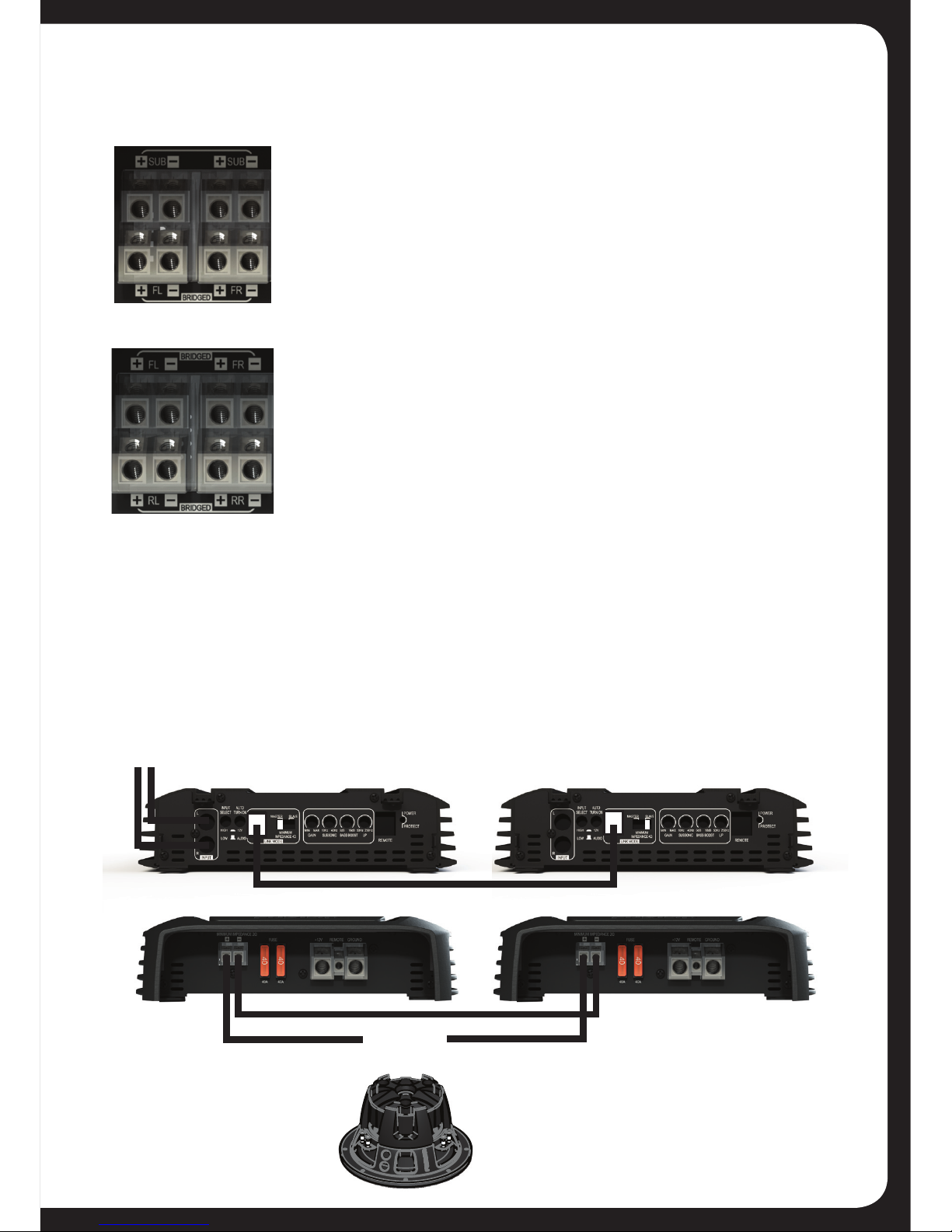
4B. INTERNALLY LINKED OUTPUT (PF-8003D) COILS IN PARALLEL
The PF-8003D amplifier provides dual output connections for
the subwoofer to simplify wiring when using two
subwoofers or a dual voice coil subwoofer. Both positive and
negative subwoofer terminals are internally connected or
linked in parallel. For dual coil (2 x 4 Ohm) or two single coil (4
Ohm) subwoofers, connect each coil to a positive and negative
terminal. For a standard single coil subwoofer connect to
either positive and either negative terminal.
4C. BRIDGED CONNECTION (PF-1802, PF-8003D
AND PF-4004)
By connecting a speaker or subwoofer to the positive terminal
of one channel and the negative of the other channel, you are
combining the output of two channels into one. This gives you
higher output levels as noted in the specifications but you
must observe the minimum load impedance as failure to do so
will result in damage to the amplifier.
PF-8003D
LINK MODE (PF-8001D)
This allows two PF-8001D amplifiers to be bridged to produce double the output power @ 4
Ohms. Do not connect a lower impedance speaker load as this could cause damage to the
amplifier and void the products warranty. The PF-8001D amplifier must be installed and linked
with the supplied Data cable. The amplifier that has the RCA input connected from the source
(head) unit must be set to “Master”. This amplifier has control of all settings and the second
amplifier must be set to “Slave”. The subwoofer must be wired following the diagram below and
the minimum speaker impedance is 4 Ohms.
Page 6
66
5
17
PF-1802
PF-4001D
5
6
7
7
16
16
16
8
8
15
17
14
10
17
5
10
12
13
13
13
15
14
14
17
15
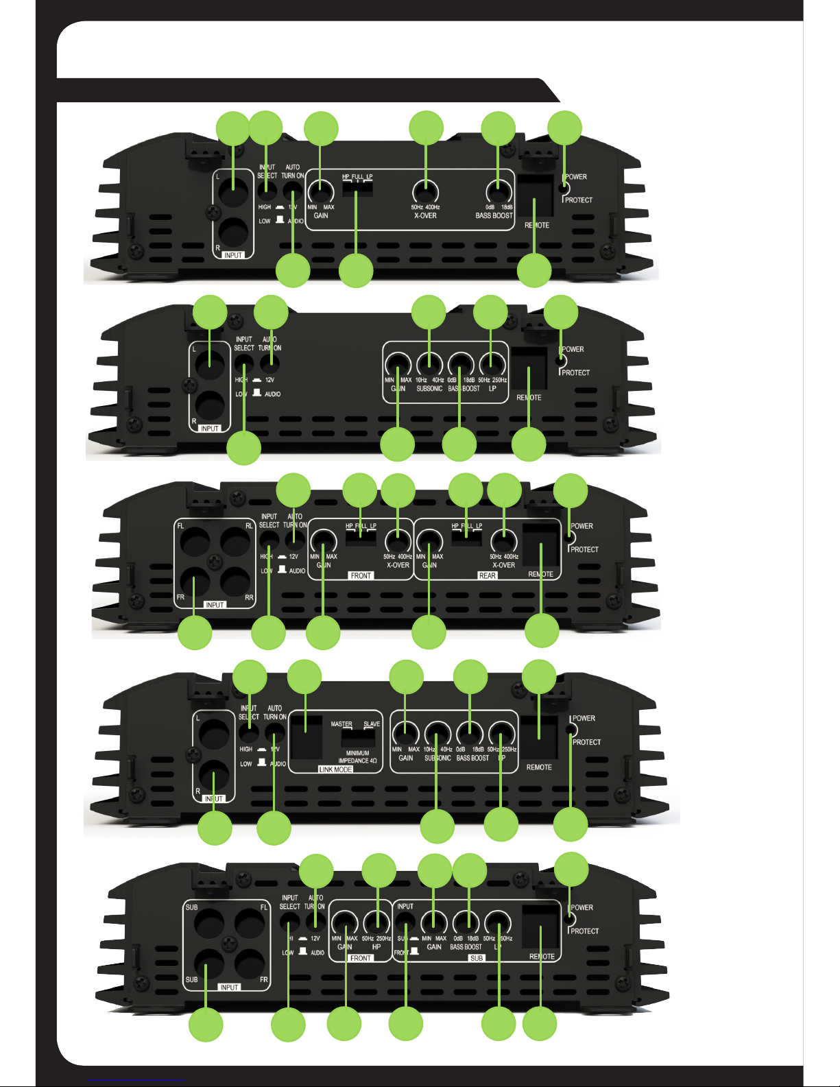
AMPLIFIER CONTROLS
7
PF-8001D
11
14
15
5
PF-4004
15
16
7
11
11
8
7
5
12
16
7
9
15
7
13
10
PF-8003D
14
17
Page 7

7
5. LOW LEVEL RCA INPUTS FRONT-REAR-SUBWOOFER
Choose the correct length RCA cables to connect the RCA outputs of the source/head unit,
to the input connectors of the amplifier. Run the RCA cables on the opposite side of the vehicle
to the power cable and vehicle wiring loom. Avoid the electric fan motor and wiring. Ensure you
follow the correct balance. (L Left = White or Black. R Right = Red).
6. LINK MODE (PF-8001D ONLY)
This function allows two PF-8001D amplifiers to be installed and linked with the supplied Data
cable. Refer to page 5 for more information
7. GAIN/LEVEL CONTROL (FRONT-REAR)
This control is used to match the input level of the amplifier to the output level of your head
unit. We recommend the method below, as failure to follow these steps may damage the audio
system.
1. Turn the amplifier Gain to zero
2. Turn the volume of the head unit to ¾ and the bass and treble to zero
3. Adjust the amplifier Gain/Level control until the desired maximum volume is achieved
without distortion.
4. Make fine adjustments to tune your install.
8. X-OVER (PF-1802 AND PF-4004 ONLY)
This is the adjustable frequency range setting for the two filter options - High Pass and Low
Pass.
9. HIGH PASS CROSSOVER FILTER
When a subwoofer is used in the system, this feature is designed to filter out all low bass
frequencies that only subwoofers should produce. See specification table for adjustable
frequency range. Set the crossover switch (11) to HP.
10. LOW PASS CROSSOVER FILTER
Ensure the crossover frequency is set at 100Hz or below. This feature must be used with a
subwoofer to filter out all mid to high frequencies that only full range speakers should produce.
See specification table for adjustable frequency range. Set the crossover switch (11) to LP.
11. HIGH PASS - FULL RANGE - LOW PASS CROSSOVER SWITCH
High Pass
See Note 9
Full Range
Set the crossover switch to full range, this setting is for large speakers (e.g. 6 X 9”) or
speakers when a subwoofer is not included in the system. The amplified audio signal is not
filtered so the full range audio signal is sent to the speakers.
Low Pass
See Note 10
Page 8

88
12. SUBSONIC FILTER (PF-4001D AND PF-8001D ONLY)
This is a variable control that filters out all subsonic bass frequencies below the set point.
These are fequencies that are not audible. These frequencies can damage subwoofers. See
specification table for adjustable frequency range.
13. BASS BOOST (PF-1802, PF-4001D, PF-8001D AND PF-8003D)
This control adjusts the bass boost at 45Hz, from 0 to +18dB. Start from 0 and slowly
increase to the desired level. Use this control with extreme care as failure to do so may result
in damage to the subwoofers.
14. REMOTE
This connection should be used with the optional remote control
(CA-RLC13 - sold separately) to adjust the bass level from any location
within the vehicle.
15. INPUT SELECT
This function switches the amplifier input between Low level (RCA
cable) and High level (speaker wire) connection. Where possible RCA
(Low Level) connections are preferable.
High
The High setting is selected when the FUSION CA-HIC13 High Level
adaptor (sold separately) is used to connect a full range signal from
the source (head) unit speaker connections to the amplifier. Simply connect the speaker wires
to the input connections observing polarity and then connect the FUSION CA-HIC13 to the RCA
inputs on the Amplifier.
Low
The Low setting is for RCA connection from the source (head) unit to the amplifier. Connect the
RCA interconnects to the appropriate Line Out connectors on the source (head) unit and
connect to the RCA inputs of the Amplifier.
This is the preferred installation method, as this provides a higher quality audio signal.
16. AUTO TURN ON
Auto Turn on switch = 12V
Select when a remote turn on wire is connected from the source (head) unit “remote wire”
output or a 12V switched supply is used. Eg power antenna wire or ignition Accessory position.
This is required when using the Low Level connection via RCA interconnects. It is optional when
using High level inputs.
Auto turn on switch = AUDIO
This feature is available with the High Level input only and the (FUSION CA-HIC13 sold
separately). The amplifier will turn on when the source (head) unit is powered on and Audio
signal is supplied via the speaker wires to the amplifier. The remote turn on wire is not required
in this installation.
FUSION recommends the use of the remote wire output from the headunit when available.
15 16
Page 9

9
17. POWER / PROTECT LED
1. When illuminated Green, indicates normal operation. Amplifier is powered on with no
faults detected.
2. When illuminated Red, indicates the amplifier is in protection mode / fault state.
See troubleshooting section on page 10.
CUSTOM INSERT
Supplied with your Performance series
amplifier is a custom insert panel created
from polycarbonate plastic. If replacing
your insert with a customised design, ensure you replace with a similar material.
Dimensions: Each insert is 1mm
(0-116”) thick and 62mm (2-7/16”)
wide. Insert lenths are shown below:
PF-1802 = 183mm (7-3/16”),
PF-4001D = 173mm (6-13/16”), PF-4004 = 323mm (12-11/16”),
PF-8001D & PF-8003D = 243mm (9-9/16”).
SUBWOOFER CONNECTION DIAGRAMS
Page 10

1010
PUBLISHED BY FUSION ELECTRONICS LIMITED: © Copyright 2013 by FUSION Electronics Limited.
All rights reserved. Specifications and design are subject to change without notice.
YOU CAN HELP PROTECT THE ENVIRONMENT! Please remember to respect the local
regulations: Hand in the non-working electrical equipment to an appropriate waste disposal
center.
TROUBLESHOOTING
PROBLEM POSSIBLE REASON SOLUTION
Amplifier not
switching on. LED
= OFF
(not ‘Red or
Green’)
• No +12V to power wire • Check fuses and connections to battery
• No power to remote wire • Check Remote Turn ON connection(s) to
head unit
• Fuse broken • Replace fuse with correct type and
amperage
• No Ground connection • Check ground cable is correctly connected
to the amplifier and vehicle / body chassis
Amplifier not
working, status
LED = Red
• Amplifier too hot • Move amplifier to vented area
• Turn head unit down
• Speaker wires shorted • Check that there are no speaker wires
shorted to another wire or to the vehicle
chassis
No sound
LED = Green
• RCA Signal • Check RCA connection to head unit
• Gain control not set up • Ensure you have set up the amplifier gain
level control
• Head Unit • Check head unit volume level
• Amplifier • Check all power, remote on and ground
connections
• Speakers • Check speakers are correctly connected.
• Check speakers for wire shorts
+
-
POSITIVE
NEGATIVE
+
-
DUAL 2 OHM VOICE COILS WIRED
IN SERIES = 4 OHM
+
-
+
-
DUAL 2 OHM VOICE COILS WIRED
IN SERIES = 4 OHM
2 X 4 OHM CONFIGURATION
WOOFERS IN PARALLEL = 2 OHM
+
-
+
-
POSITIVE
NEGATIVE
+
-
DUAL 4 OHM VOICE COILS WIRED
IN SERIES = 8 OHM
+
-
+
-
DUAL 4 OHM VOICE COILS WIRED
IN SERIES = 8 OHM
2 X 8 OHM CONFIGURATION
WOOFERS IN PARALLEL = 4 OHM
+
-
Page 11

11
Version 2.1
PF-1802 (2 voies) PF-4004 (4 voies)
Classe Class-AB Class-AB
Alimentation 1 200 W 2 400 W
Réponse en fréquence de 20 Hz à 20 kHz de 20 Hz à 20 kHz
Dimensions 246 mm (9-11/16”) x 200 mm (7-7/8”)
x 51 mm (2”)
386 mm (15-3/16”) x 200 mm (7-7/8”)
x 51 mm (2”)
Puissances nominales
RMS
65 W x 2 à 4 ohms 1 % THD+N
90 W x 2 à 2 ohms 1 % THD+N
180 W x 1 à 4 ohms avec pontage 1 %
THD+N
80 W x 4 à 4 ohms 1 % THD+N
100 W x 4 à 2 ohms 1 % THD+N
200 W x 2 à 4 ohms avec pontage 1 %
THD+N
Rapport signal/bruit >50 dB >50 dB
Filtres passe-haut et
passe-bas
12 dB par octave 12 dB par octave
Amplification des
basses à 45 Hz
de 0 à +18 dB N/D
Plage de coupure de 50 Hz à 400 Hz de 50 Hz à 400 Hz
Plage d'entrée de basse
puissance
de 0,35 V à 10 V de 0,35 V à 10 V
Plage d'entrée de haute
puissance
de 1 V à 30 V de 1 V à 30 V
Impédance de charge
minimale
2 ohms stéréo et 4 ohms avec pontage 2 ohms stéréo et 4 ohms avec pontage
PF-4001D (monobloc) PF-8001D (monobloc) PF-8003D (3 voies)
Classe Class-D Class-D Class-D
Alimentation 1 600 W 3 200 W 2 400 W
Réponse en fréquence 10Hz - 250Hz 10Hz - 250Hz 10Hz - 20kHz
Dimensions 236 mm (9-1/4”) x 200 mm (7-7/8”)
x 51 mm (2”)
306 mm (12”) x 200 mm (7-7/8”) x
51 mm (2”)
306 mm (12”) x 200 mm (7-7/8”) x
51 mm (2”)
Puissances nominales
RMS
250 W x 1 à 4 ohms 1 % THD
400 W x 1 à 2 ohms 1 % THD
500 W x 1 à 4 ohms 1 % THD
800 W x 1 à 2 ohms 1 % THD
Mode liaison (deux PF-8001D)
1 600 W x 1 à 4 ohms 1 % THD
Avant 90 W x 2 à 4 ohms
150 W x 2 à 2 ohms 1 % THD+N
Subwoofer 230 W x 1 à 4 ohms
500 W x 1 à 2 ohms 1 % THD+N
Rapport signal/bruit >50 dB >50 dB >50 dB
Filtres passe-haut et
passe-bas
12 dB par octave 12 dB par octave 12 dB par octave
Filtre subsonique 12 dB par octave 12 dB par octave 12 dB par octave
Plage du filtre passe-bas de 50 Hz à 250 Hz de 50 Hz à 250 Hz de 50 Hz à 250 Hz
Plage du filtre subsonique de 10 Hz à 40 Hz de 10 Hz à 40 Hz de 10 Hz à 40 Hz
Amplification des basses
à 45 Hz
de 0 à +18 dB de 0 à +18 dB de 0 à +18 dB
Plage d'entrée de basse
puissance
de 0,35 V à 10 V de 0,35 V à 10 V de 0,35 V à 10 V
Plage d'entrée de haute
puissance
de 1 V à 30 V de 1 V à 30 V de 1 V à 30 V
Impédance de charge
minimale
2 Ohm 2 ohms et 4 ohms en mode liaison 2 ohms
SPÉCIFICATIONS DE L'AMPLIFICATEUR
REMARQUE :LA SÉRIE
D'AMPLIFICATEURS
PERFORMANCE
PRÉSENTE UNE
IMPÉDANCE DE CHARGE
MINIMALE DE 2 OHMS
PAR VOIE 4 OHMS AVEC
PONTAGE
Généralités
Exigences
d'alimentation
+12 V CC
(masse négative)
Tension de
fonctionnement
de 10,5 à 16 V
Section minimale
recommandée
du câble
d'alimentation/
masse
5,2 mm (4 AWG)
Dimension
recommandée
pour les fusibles
en série
Câble 5,2 mm
- 80 A
FRANÇAIS
Page 12

1212
INSTALLATION DE L’AMPLIFICATEUR
AVERTISSEMENTS LIÉS À L'INSTALLATION
1. Assurez-vous que le fil +12 V soit déconnecté de la batterie avant de connecter tout nouvel
équipement.
2. Assurez-vous que l'emplacement et les orifices de montage de l'amplificateur n'entrent pas en
conflit avec le réservoir d'essence, les durits de freinage ou le faisceau électrique.
3. Assurez-vous que l'amplificateur soit solidement fixé au véhicule afin d'éviter qu'il ne se déplace et
provoque des dégâts en cas d'accident.
4. Assurez-vous que tous les fils soient tenus à distance des éléments tranchants et ne soient pas
pincés ou écrasés, ce qui pourrait endommager le système audio.
5. Assurez-vous que l'emplacement de montage permette une circulation d'air suffisante autour de
l'amplificateur. Si l'amplificateur est monté dans un espace clos, un ventilateur de 3 pouces muni
d'un conduit d'aération doit être utilisé afin d'assister le refroidissement.
6. Ne montez pas un amplificateur sur le caisson d'un subwoofer, car une exposition prolongée aux
vibrations pourrait l'endommager.
7. Assurez-vous d'utiliser un fil/câble d'une section au moins égale à la section recommandée pour
toutes les connexions de l'amplificateur.
8. Un montage approprié est très important pour l'espérance de vie d'un amplificateur. Sélectionnez
un emplacement qui le préserve de l'humidité. Souvenez-vous qu'un amplificateur ne doit jamais
être monté à l'envers. Un montage à l'envers compromettrait la dissipation thermique via le
dissipateur prévu à cet effet et pourrait compromettre la protection thermique du circuit.
BRANCHEMENT
Assurez-vous que le système audio soit éteint avant d'effectuer tout branchement sur l'amplificateur,
les haut-parleurs ou la source audio. Le non-respect de cette précaution peut entraîner une détérioration permanente du système audio. Assurez-vous d'employer des câbles de section appropriée pour
toutes les connexions. Reportez-vous au schéma de détermination de câble ci-dessous afin de trouver
la section de câble adaptée à votre installation.
AMPÉRAGE
TOTAL
LONGUEUR
DU CÂBLE
>
M 0 - 1 1 - 2 2 - 3 3 - 4 4 - 5 5 - 6 6 - 7 7 - 9
FT 0- 4 4 - 7 7 - 10 10 - 13 13 - 16 16 - 19 19 - 22 22 - 28
0 - 20 14 12 12 10 10 8 8 8
20 - 35 12 10 8 8 6 6 6 4
35 - 50 10 8 8 6 4 4 4 4
50 - 65 8 8 6 4 4 4 4 2
65 - 85 6 6 4 4 2 2 2 0
85 - 105 6 6 4 2 2 2 2 0
10 5 - 12 5 4 4 4 2 0 0 0 0
125 - 150 2 2 2 0 0 0 0 0
Le diagramme ci-dessus indique les sections de câble à utiliser, si une perte supérieure à 0,5 V est
acceptable. En cas d'utilisation de câble en aluminium, les sections peuvent être supérieures afin de
compenser. La détermination de la section des câbles prend en compte la résistance des bornes de
connexion.
Page 13

13
1 3
2
PF-1802 PF-4001D PF-4004
PF-8003D PF-8001D
CONNEXIONS DE L'AMPLIFICATEUR
1. ALIMENTATION + 12 V
Assurez-vous que TOUTES les autres connexions de
câbles soient effectuées avant de connecter ce câble
à la batterie. Les amplificateurs FUSION doivent être
connectés directement à la borne 12 V de la batterie
à l'aide d'un câble de section appropriée. Commencez
par la batterie du véhicule puis faites courir le câble
jusqu'à l'amplificateur. FUSION recommande d'utiliser
des bagues en caoutchouc lors du passage des câbles
à travers un panneau métallique, afin d'éviter les
arêtes ou angles tranchants qui pourraient entamer
le revêtement isolant du câble.Évitez de faire courir un câble à proximité des éléments du moteur ou
du système de chauffage. Un fusible ou un coupe-circuit monté en série DOIT être installé à moins de
30 cm (12”) de votre batterie. Cela préviendra le risque potentiel d'incendie provoqué par un courtcircuit du câble d'alimentation (consultez le tableau des caractéristiques pour déterminer les valeurs
recommandées pour le fusible/coupe-circuit monté en série). Branchez l'autre extrémité de votre câble
d'alimentation à la batterie, mais souvenez-vous de laisser le fusible ou le coupe-circuit ouvert jusqu'à ce
que toutes les autres connexions de câbles soient effectuées.
2. ALLUMAGE À DISTANCE
Ce branchement permet d'allumer l'amplificateur et doit être connecté au fil « Allumage à distance » de
l'unité principale. Si aucun n'est disponible, une source +12 V commutée doit être utilisée, telle qu'un fil
d'antenne alimentée ou un raccordement +12 V de type ACC (accessoire activé au démarrage). Si vous
utilisez des sources de haute puissance (pour vos haut-parleurs) et qu'un fil d'allumage à distance n'est
pas disponible, alors le commutateur « AutoTurn-On » doit être réglé sur audio.
3. MASSE
Branchez d'abord le câble de masse/terre à votre amplificateur. Assurez-vous que son emplacement
soit adapté à cet usage (de préférence sur le châssis ou le plancher). Examinez la zone que vous
souhaitez utiliser afin de vous assurer qu'elle est exempte de fils, de prises de vide et de durits de
freinage ou d'essence. Utilisez une brosse métallique ou du papier de verre pour exposer la surface
du métal nu, ce qui fournira un meilleur contact électrique pour votre connexion à la masse. Utilisez la
même section pour vos câbles de masse et d'alimentation. Fixez le câble de masse au point de mise à
la masse à l'aide d'un boulon, d'une rondelle en étoile et d'un écrou. Appliquez du silicone à vulcanisation
neutre sur le boulon et le métal nu afin de prévenir l'infiltration d'eau et la formation de rouille. Branchez
l'autre extrémité de votre câble de masse à l'amplificateur.
4A. BRANCHEMENT DE LA SORTIE
HAUT-PARLEUR
Assurez-vous que la polarité soit respectée lors du
branchement des haut-parleurs/subwoofers.
Haut-parleur d'une impédance d'au moins 2 ohms pour
un fonctionnement en stéréo (par voie).
Haut-parleur d'une impédance d'au moins 4 ohms pour
un fonctionnement avec pontage.
PF-1802
Page 14

1414
SUBWOOFER + SUBWOOFER -
MINIMUM
4 OHM
MASTER SLAVE
+ -
RCA
INPUT
+
-
PF-4004
4B. SORTIE RELIÉE EN INTERNE (PF-8003D) - BOBINES EN
PARALLÈLE
L'amplificateur PF-8003D fournit une double connexion de sortie afin
de simplifier le câblage lors de l'utilisation de deux subwoofers ou d'un
subwoofer à double bobine. Les bornes positives et négatives du subwoofer
sont connectées en interne ou reliées en parallèle. Pour les subwoofers à
double bobine (2 x 4 ohms) ou munis de deux bobines simples (4 ohms),
branchez chaque bobine sur une borne positive et négative. Pour un
subwoofer standard à bobine simple, branchez celle-ci sur une borne
positive ou négative.
4C. BRANCHEMENT AVEC PONTAGE (PF-1802, PF-8003D ET
PF-4004)
En connectant un haut-parleur ou un subwoofer à la borne positive d'une
voie et à la borne négative de l'autre voie, vous combinez les sorties de
deux voies en une seule. Cela vous procure des niveaux plus élevés en
sortie, comme mentionné dans les caractéristiques, mais vous devez
respecter l'impédance de charge minimale, car le non-respect de cette
précaution endommagerait l'amplificateur.
PF-8003D
MODE LIAISON (PF-8001D)
Ce mode permet à deux amplificateurs PF-8001D d'être pontés afin de délivrer une puissance de
sortie double à 4 ohms. Ne branchez pas un haut-parleur de plus faible impédance car cela pourrait
endommager l'amplificateur et annulerait la garantie du produit. L'amplificateur PF-8001D doit être
installé et connecté à l'aide du câble de données fourni. L'amplificateur dont l'entrée RCA est reliée à la
source (unité principale) doit être réglé sur « Master ». Cet amplificateur contrôle tous les paramètres et
le deuxième amplificateur doit être réglé sur « Slave ». Le subwoofer doit être branché conformément au
diagramme ci-dessous et l'impédance minimale des haut-parleurs est de 4 ohms.
Page 15

15
5
17
PF-1802
PF-4001D
5
6
7
7
16
16
16
8
8
15
17
14
10
17
5
10
12
13
13
13
15
14
14
17
15
COMMANDES DE L'AMPLIFICATEUR
7
PF-8001D
11
14
15
5
PF-4004
15
16
7
11
11
8
7
5
12
16
7
9
15
7
13
10
PF-8003D
14
17
Page 16

1616
5. ENTRÉES RCA AVANT-ARRIÈRE-SUBWOOFER DE BASSE PUISSANCE
Choisissez des câbles RCA de longueur adaptée au branchement des sorties RCA de la source audio
ou de l'unité principale sur les connecteurs d'entrée de l'amplificateur. Faites courir les câbles RCA du
côté du véhicule où ne circulent pas le câble d'alimentation et le faisceau électrique. Évitez le moteur et le
faisceau du ventilateur électrique. Assurez-vous de respecter un bon équilibre. (L Gauche = Blanc ou Noir.
R Droite = Rouge).
6. MODE LIAISON (PF-8001D UNIQUEMENT)
Cette fonctionnalité permet à deux amplificateurs PF-8001D d'être installés et connectés à l'aide du câble
de données fourni. Consultez la page 5 pour obtenir plus d'informations.
7. COMMANDE DU GAIN/NIVEAU (AVANT-ARRIÈRE)
Cette commande est utilisée pour faire correspondre le niveau d'entrée de l'amplificateur au niveau de
sortie de votre unité principale. Nous recommandons la méthode ci-dessous, car le non-respect de ces
étapes peut endommager le système audio.
1. Réglez le gain de l'amplificateur sur zéro.
2. Réglez le volume de l'unité principale sur ¾, puis les niveaux de basses et d'aigus sur zéro.
3. Réglez la commande de gain/niveau de l'amplificateur jusqu'à ce que le volume maximal souhaité soit
atteint sans distorsion.
4. Effectuez des réglages minutieux pour parfaire le réglage de votre installation.
8. X-OVER (PF-1802 ET PF-4004 UNIQUEMENT)
Il s'agit du paramètre de la plage réglable de fréquences pour les deux options de filtre : passe-haut et
passe-bas.
9. FILTRE PASSE-HAUT
Quand un subwoofer est utilisé dans le système, cette caractéristique permet de filtrer toutes les basses
fréquences que seuls les subwoofers doivent reproduire. Consultez le tableau des caractéristiques pour
le réglage des fréquences. Réglez le commutateur du filtre (11) sur HP.
10. FILTRE PASSE-BAS
Assurez-vous que la fréquence de coupure soit réglée sur 100 Hz ou moins. Cette fonctionnalité doit être
utilisée avec un subwoofer, afin de filtrer toutes les fréquences du médium à l'aigu que seuls des hautparleurs à gamme étendue doivent reproduire. Consultez le tableau des caractéristiques pour le réglage
des fréquences. Réglez le commutateur du filtre (11) sur LP.
11. COMMUTATEUR DU FILTRE PASSE-HAUT - PLEINE GAMME - PASSE-BAS
Passe-haut
Voir la remarque 9
Pleine gamme
Réglez le commutateur du filtre sur Full range, ce paramètre étant destiné aux haut-parleurs de
grand diamètre (ex. : 6 x 9”) ou utilisés sans subwoofer. Le signal audio amplifié n'est pas filtré afin que
l'intégralité de la gamme de ce signal soit envoyée aux haut-parleurs.
Passe-bas
Voir la remarque 10
Page 17

17
12. FILTRE SUBSONIQUE (PF-4001D ET PF-8001D UNIQUEMENT)
Il s'agit d'une commande variable qui filtre toutes les fréquences de basses subsoniques inférieures au
seuil défini. Ces fréquences ne sont pas audibles. Elles peuvent endommager les subwoofers. Consultez le
tableau des caractéristiques pour le réglage des fréquences.
13. AMPLIFICATION DES BASSES (PF-1802, PF-4001D, PF-8001D ET PF-8003D)
Cette commande ajuste l'amplification des basses à 45 Hz, de 0 à +18 dB. Commencez à 0 et
augmentez doucement jusqu'au niveau souhaité. Utilisez cette commande avec une extrême prudence,
car le non-respect de cette consigne peut endommager les subwoofers.
14. COMMANDE À DISTANCE
Cette connexion doit être utilisée avec la télécommande optionnelle (CARLC13, vendue séparément) afin d'ajuster le niveau de basses depuis
n'importe quel endroit du véhicule.
15. SÉLECTION DE L'ENTRÉE
Cette fonction commute l'entrée de l'amplificateur entre les connexions basse
puissance (câble RCA) et haute puissance (câblage des haut-parleurs). Chaque
fois que possible, les connexions RCA (basse puissance) sont préférables.
Haute puissance
Le réglage High est sélectionné lorsque l'adaptateur de haute puissance
FUSION CA-HIC13 (vendu séparément) est utilisé pour connecter un signal
pleine gamme depuis les connexions des haut-parleurs de l'unité source (principale) à l'amplificateur.
Branchez simplement les fils des haut-parleurs aux connexions de l'entrée en respectant la polarité, puis
branchez le FUSION CA-HIC13 aux entrées RCA de l'amplificateur.
Basse puissance
Le paramètre Low correspond à la connexion RCA depuis la source audio (principale) à l'amplificateur.
Branchez les interconnexions RCA aux connecteurs Sortie ligne appropriés sur la source audio
(principale) puis branchez les entrées RCA sur l'amplificateur.
Ceci est la méthode d'installation à privilégier, car elle fournit une meilleure qualité de signal audio.
16. ALLUMAGE AUTOMATIQUE
Commutateur d'allumage automatique = 12 V
Sélectionnez cette option lorsqu'un fil d'allumage à distance est relié depuis la sortie « fil de commande
à distance » de la source audio (principale) ou lorsqu'une alimentation 12 V commutée est utilisée. Ex. :
fil d'antenne alimentée ou emplacement pour accessoire activé au démarrage. Cela est nécessaire lors
de l'utilisation de la connexion de basse puissance via les interconnexions RCA. C'est optionnel en cas
d'utilisation des entrées de haute puissance.
Commutateur d'allumage automatique = AUDIO
Cette fonctionnalité est disponible uniquement avec l'entrée de haute puissance et le FUSIONCA-HIC13
(vendu séparément). L'amplificateur s'allume lorsque la source audio (principale) est mise sous tension et
qu'un signal audio est fourni via les fils des haut-parleurs jusqu'à l'amplificateur. Le fil d'allumage à distance
n'est pas nécessaire dans cette installation.
FUSION recommande d'utiliser la sortie du fil de commande à distance depuis la source principale
lorsque celle-ci est disponible.
15 16
Page 18

1818
17. LED D'ALIMENTATION/PROTECTION
1. Allumée en Vert, elle indique un fonctionnement normal. L'amplificateur est alimenté sans erreur
détectée.
2. Allumée en Rouge, elle indique que l'amplificateur est en mode de protection/état de défaut.
Consultez la section de dépannage en page 10.
INSERT PERSONNALISÉ
Un insert personnalisable en polycarbonate
est fourni avec votre amplificateur de la série
Performance. Si vous remplacez votre insert
par une création personnalisée, veillez à
utiliser un matériau similaire.
Dimensions : chaque insert mesure 1 mm
(0-116”) d'épaisseur et 62 mm (2-7/16”)
de largeur. Les longueurs des inserts sont
indiquées ci-dessous :
PF-1802 = 183 mm (7-3/16”),
PF-4001D = 173 mm (6-13/16”), PF-4004 = 323 mm (12-11/16”),
PF-8001D et PF-8003D = 243 mm (9-9/16”).
DIAGRAMMES DE BRANCHEMENT DU SUBWOOFER
DOUBLE BOBINE 2 OHMS
BRANCHÉE EN SÉRIE = 4 OHMS
DOUBLE BOBINE 4 OHMS
BRANCHÉE EN PARALLÈLE = 2 OHMS
POSITIF
POSITIF
NÉGATIF
NÉGATIF
Page 19

19
PUBLIÉ PAR FUSION ELECTRONICS LIMITED : © Copyright 2013 FUSION Electronics Limited.
Tous droits réservés. Les caractéristiques et la conception peuvent être modifiées sans préavis.
VOUS POUVEZ CONTRIBUER À PRÉSERVER L'ENVIRONNEMENT ! Rappelez-vous de
respecter les règlementations locales : confiez les équipements électriques défectueux à un
centre approprié au traitement de ces déchets.
DÉPANNAGE
PROBLÈME CAUSE POSSIBLE SOLUTION
L'amplificateur
ne s'allume pas.
LED = ÉTEINTE
(ni Rouge, ni
Verte)
• Pas de courant +12 V
sur le fil d'alimentation.
• Vérifiez les fusibles et les branchements à la batterie.
• Câble de télécommande
non alimenté
• Vérifiez les connexions d'allumage de la télécommande à
l'unité principale.
• Fusible cassé • Remplacez le fusible par un autre présentant les mêmes
type et ampérage.
• Pas de connexion à la
masse
• Vérifiez que le câble de masse est correctement branché à
l'amplificateur et à la carrosserie ou au châssis du véhicule.
L'amplificateur
ne fonctionne
pas, LED d'état )
= Rouge.
• L'amplificateur est trop
chaud.
• Déplacez l'amplificateur dans un endroit ventilé.
• Éteignez l'unité principale.
• Fils des haut-parleurs en
court-circuit.
• Vérifiez qu'aucun fil des haut-parleurs n'est en contact avec
un autre fil ou le châssis du véhicule.
Pas de son
LED = Verte
• Signal RCA • Vérifiez le branchement RCA sur l'unité principale.
• Commande de gain non
configurée
• Assurez-vous d'avoir configuré la commande du niveau de
gain de l'amplificateur.
• Unité principale • Vérifiez le niveau du volume de l'unité principale.
• Amplificateur • Vérifiez l'ensemble des branchements d'alimentation, de
télécommande et de masse.
• Haut-parleurs • Vérifiez que les haut-parleurs sont correctement branchés.
• Contrôlez l'absence de court-circuit au niveau des haut-
parleurs.
+
-
POSITIVE
NEGATIVE
+
-
DUAL 2 OHM VOICE COILS WIRED
IN SERIES = 4 OHM
+
-
+
-
DUAL 2 OHM VOICE COILS WIRED
IN SERIES = 4 OHM
2 X 4 OHM CONFIGURATION
WOOFERS IN PARALLEL = 2 OHM
+
-
+
-
POSITIVE
NEGATIVE
+
-
DUAL 4 OHM VOICE COILS WIRED
IN SERIES = 8 OHM
+
-
+
-
DUAL 4 OHM VOICE COILS WIRED
IN SERIES = 8 OHM
2 X 8 OHM CONFIGURATION
WOOFERS IN PARALLEL = 4 OHM
+
-
CONFIGURATION 2 x 4 OHMS
SUBWOOFERS EN PARALLÈLE = 2 OHMS
CONFIGURATION 2 x 8 OHMS
SUBWOOFERS EN PARALLÈLE = 4 OHMS
DOUBLE BOBINE 2 OHMS
BRANCHÉE EN SÉRIE = 4 OHMS
DOUBLE BOBINE 4 OHMS
BRANCHÉE EN SÉRIE = 8 OHMS
DOUBLE BOBINE 2 OHMS
BRANCHÉE EN SÉRIE = 4 OHMS
DOUBLE BOBINE 4 OHMS
BRANCHÉE EN SÉRIE = 8 OHMS
POSITIF
POSITIF
NÉGATIF
NÉGATIF
Page 20

Specifications and design are subject to change without notice
 Loading...