

Page 1
INSTALLATION MANUAL
VEHICLE SECURITY SYSTEM
CE-SS200
Page 2

FUSION CULTURE
TABLE OF CONTENTS
There’s no point doing something if no one notices. We’ve always
believed the way to make things happen is by getting noticed. From
our product, to our demo cars, to our events, FUSION is about
making some noise.
Now you are ready. Step out of the shadows and announce you’ve
arrived in a world where the old limits are left behind. Where
technology is creatively combined with the latest in product
innovation. Where new levels of entertainment are delivered with
outstanding performance and quality. Our development team create
distinctively different products; subwoofers, amplifiers, speakers and
peripherals that redefine what can be done in car audio.
Leave the old behind and push the limits of what can be achieved in
car audio. Make some noise.
For more information about FUSION Electronics visit our website at
www.fusionelectronics.com
or email technical@fusionelectronics.co.nz
PROFESSIONAL INSTALLATION STONGLY RECOMMENDED
Installation Precautions:
1. Roll down window to avoid locking keys in vehicle during installation
2. Avoid mounting components or routing wires near hot surfaces
3. Avoid mounting components or routing wires near moving parts
4. Tape or loom wires under hood for protection and appearance
5. Use grommets when routing wires through metal surfaces
6. Use a voltmeter for testing and verifying circuits
2
• PROGRAMMING REMOTES . . . . . . . . . . . . . . . . . . . . . . . . . . . . . . . . . pg 4
• ALARM FEATURES PROGRAMMING . . . . . . . . . . . . . . . . . . . . . . . . . pg 5
• ADJUSTING THE SENSITIVITY LEVEL . . . . . . . . . . . . . . . . . . . . . . . . . pg 8
• WIRING DIAGRAMS. . . . . . . . . . . . . . . . . . . . . . . . . . . . . . . . . . . . . . . . pg 9
• CENTRAL LOCKING DIAGRAMS . . . . . . . . . . . . . . . . . . . . . . . . . . . . . pg 11
• SPECIFICATIONS . . . . . . . . . . . . . . . . . . . . . . . . . . . . . . . . . . . . . . . . . .pg 15
RECORD YOUR PRODUCT DETAILS HERE:
MODEL NUMBER _______________________________ DATE OF PURCHASE________________
AFFIX RECEIPT HERE
V 2.0
3
Page 3
PROGRAMMING REMOTES
1. Turn the ignition switch ‘OFF/ON’ 3 times (within 15 seconds)
and leave in the ON position.
2. Push the valet switch 3 times, and hold on the 3rd push until a long
chirp is heard from the siren, and then release the valet switch. You
are now in the remote programming mode.
3. Press and hold any button of the remote until the siren responds
with a confirming chirp, this indicates the remote has been stored
into memory.
4. If you have additional remotes (up to 4 in total) that need to be
programmed, repeat step 3 for each remote.
Exit Programming: Turn ignition to ‘OFF’ position, or wait for 15
seconds. Three long chirps and three indicator light flashes will
confirm exit.
Note: This mode will only retain the last 4 remote transmitters
programmed. If the remote memory is exceeded, the security system will
start deleting remote’s from memory in chronological order.
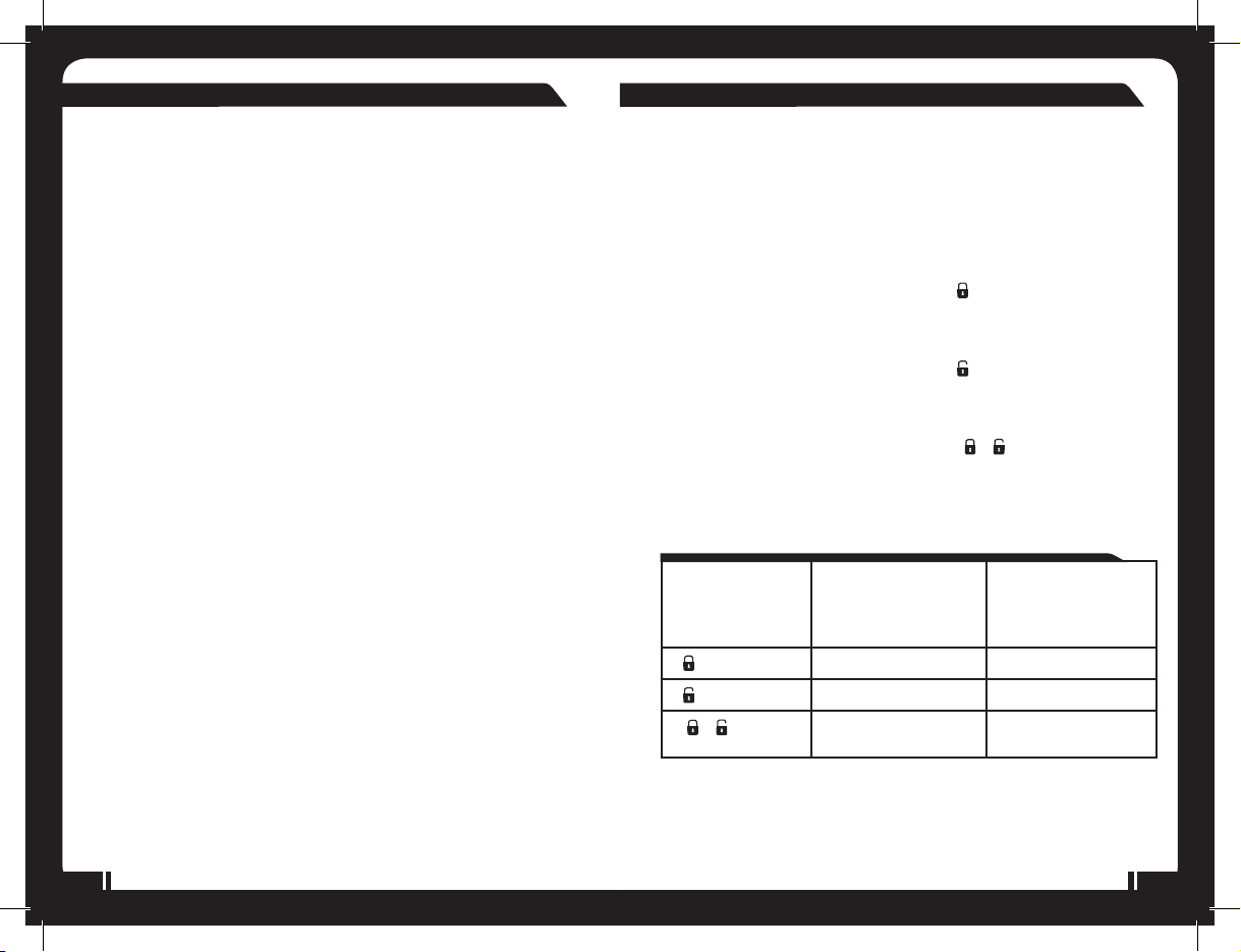
ALARM FEATURES PROGRAMMING:
ALARM FEATURE “I” PROGRAMMING:
1. Turn the ignition ‘switch ‘ON/OFF’ 3 times (within 15 seconds)
and leave in the OFF position on the 3rd time.
2. Push the valet switch twice, and hold on the 2nd push until one
short chirp, followed by one long chirp is heard then release the valet
switch. You are now in the alarm feature ‘I’ programming mode.
3. A; Press and release the remote button
feature ‘1’ to be changed.
The siren will chirp and the LED will indicate the new setting
B; Press and release the remote button corresponding to the
feature ‘2’ to be changed.
The siren will chirp and the LED will indicate the new setting
C; Press and release the remote buttons + corresponding to
the feature ‘3’ to be changed.
The siren will chirp and the LED will indicate the new setting
Note: The factory default setting is always [1] LED flash, [1] chirp.
corresponding to the
Press remote
button
1
2
3 +
Exit Programming: Turn ignition to ‘ON’ position, or wait 15 seconds.
Three long chirps will confirm exit.
4
One Chirp / LED one
flash
Factory Default
Setting
Chirps on Chirps off
Automatic Rearm On Automatic Rearm Off
Instant Door Ajar
Warning
Two Chirps / LED two
flashes
45 second Delay Door
Ajar warning
5
Page 4

ALARM FEATURE “II” PROGRAMMING:
ALARM FEATURE “III” PROGRAMMING:
1. Turn the Ignition ‘switch ‘ON/OFF’ 3 times (within 15 seconds),
and leave in the OFF position.
2. Push the valet switch 4 times and hold on the 4th push until two short
chirps and one long chirp is heard, and then release the valet switch.
You are now in the alarm feature ‘II’ programming mode.
3. A; Press and release the remote button
corresponding to the
feature ‘1’ to be changed.
The siren will chirp and the LED will indicate the new setting.
B; Press and release the remote button corresponding to the
feature ‘2’ to be changed.
The siren will chirp and the LED will indicate the new setting.
C; Press and release the remote buttons + corresponding to
the feature ‘3’ to be changed.
The siren will chirp and the LED will indicate the new setting.
Note: The factory default setting is always [1] LED flash, [1] chirp.
Press
remote
button
One Chirp /
LED one flash
Factory
Two Chirps /
LED two flashes
Three Chirps /
LED three flashes
Default Setting
1
0.9 - second
door lock
3.0 - second
door lock pulse
double pulse
unlock
pulses
2
3 +
Active arming Passive arming
without passive
door locking
Ignition
controlled door
locks & unlocks
Without ignition
controlled door
locks & unlocks
Passive arming
with passive door
locking
Exit Programming: Turn ignition to ‘ON’ position, or wait for
15 seconds. Three long chirps will confirm exit.
6
1. Turn the ignition ‘switch ‘ON/OFF’ 3 times (within 15 seconds),
and leave in the OFF position.
2. Push the valet switch 6 times and hold on the 6th push until three
short chirps and one long chirp is heard, and then release the valet
switch. You are now in the Alarm feature ‘III’ programming mode.
3. A; Press and release the remote button corresponding to the
feature ‘1’ to be changed.
The siren will chirp and the LED will indicate the new setting.
B; Press and release the remote button corresponding
to the feature ‘2’ to be changed.
The siren will chirp and the LED will indicate the new setting.
C; Press and release the remote buttons + corresponding to
the feature ‘3’ to be changed.
The siren will chirp and the LED will indicate the new setting.
Note: The factory default setting is always [1] LED flash, [1] chirp.
Press remote
button
One Chirp / LED one
flash
Two Chirps / LED
two flashes
Factory Default
Setting
1
2
3 +
Red/white wire =
trunk/boot (Channel
3) output
Anti car jacking off Anti car jacking on
Shock sensor
program mode
Red/white wire =
two step door unlock
output
Exit Programming: Turn Ignition to ‘ON’ position, or wait for 15
seconds. Three long chirps will confirm exit.
7
Page 5

ADJUSTING THE SENSITIVITY LEVEL OF THE SHOCK SENSOR
1. Turn the ignition ‘switch ‘ON/OFF’ 3 times (within 15 seconds) and
leave in the OFF position.
2. Push the valet switch 6 times and hold on the 6th push until three
short chirps and one long chirp is heard, and then release the valet
switch. You are now in the alarm feature ‘Shock Sensor’
programming mode.
3. Press and hold
indicate the unit is ready to accept adjustments of the second stage
of the shock sensor (full alarm).
4. Pressing the button on the remote once will decrease the sensitivity
level by one, each time a decrease is made the siren will respond
with one chirp, while 2 chirp’s indicates the minimum sensitivity
setting.
5. Pressing button on the remote once will increase sensitivity level by
one, each time an increase is made the siren will respond with
one chirp, while 2 chirp’s indicates the maximum sensitivity setting.
6. Hit the bumper or strong metal part of the vehicle to test the
threshold level of the sensor.
a). Activate the warn-away (first stage of the shock sensor), the siren
will emit a short chirp.
b). Activate the full alarm (second stage of the shock sensor), the
siren will emit a long chirp.
7. When you are satisfied with the second stage of the shock sensor
settings, press and hold and buttons simultaneously for
2 seconds. Two long siren chirps will indicate the unit is ready
to accept adjustments of the first stage of the shock
sensor (warn-away).
8. Follow the steps 4, 5 and 6 to adjust the warn-away sensitivity.
9. When you are satisfied with the setting, press and buttons
simultaneously. One long siren chirp indicates the unit has confirmed
the setting.
button for 2 seconds. One long siren chirp will
WIRING DIAGRAM
Black Antenna Wire
2Pin
Valet Switc h
Blue
A: MAIN 6 PIN WIRE HARNESS:
1. White Wire : Turn Indica tor Relay Ou tput
2. Red / Blue Wire: Turn Indicator Relay Power input
3. White W ire: Turn Indicator Rela y Output
4. Black Wire: Ground to Vehicle FRAME
5. Brown Wire: Positive output To Siren
6. Red Wire: +12V To Constant Battery Source
6Pin
Whi te
2Pin
Whi te
6Pin
Whi te
6Pin
Whi te
Turn Indicator
6PinMiniConnector
6PinDoorLock/Unlock
Wire harness
Main 6 Pin Wire h arne ss
10A Fuse
3A Fuse
LED Indicator
Note: If 20 seconds of inactivity expire, or the ignition is turned on during
the above steps, the unit will exit the programing mode and return to the
disarmed mode. Three long chirps will confirm exit.
8
9
Page 6

Y
B: 6 PIN MINI CONNECTOR WIRE HARNESS:
1. Violet Wire: Positive Door Pin SwitchInput
2. Blue Wire: Instant Trigger Ground Input
3. Green Wire: Negative Door Pin Switch Input
4. Yellow Wire: To Ignition Switched + 12 V
5. Orange Wire: 200mA Grounded when armed
6. Red/White Wire: (-) 200mA Programmable Output
Channel 3 / 2 Step Door Unlock.
12V
From ignition switch
ellowwire
Red wire
85
C: 6PIN DOOR LOCK/UNLOCK WIRE HARNESS:
(See central locking diagrams)
87a
Cut
30
86
12V
To start solenoid
White wire
Orange
wire
A: CENTRAL LOCKING DIAGRAMS
(After market Door Motors)
INSTALLING DOOR LOCK MOTORS (2 WIRE)
Green/ white
Blue/ white
Blue/ red
Green/ red
Blue/ yellow
Green/ yellow
INSTALLING 4 DOOR LOCK MOTORS (WITH 5-WIRE LOCK MOTOR)
Blue/ red
Green/ red
Green/ white
Blue/ white
Blue/ yellow
Green/ yellow
+12V
+12V
To Door
UnlockControl
Wire
To Door
LockC ontrol
Wire
Blue/Red
Blue/White
Blue/Yellow
Green/Red
Green/White
Green/Yellow
Wire:
Wire:
Wire:
Wire:
Wire:
Wire:
- Door Unlock Relay
(87a)
)-DoorUnlockRelay
(30
- Door Unlock Relay
(87)
-Door LockRelay
(87a)
) -Door Lock Relay
(30
-DoorLockRelay
(87)
B: CENTRAL LOCKING DIAGRAMS
(Factory Door Locking System)
NEGATIVE TRIGGER DOOR LOCK SYSTEM
Green / white
Blue / white
Door Lock
Door unlock
Master
Lockin g
Swit ch
Green / yellow
Blue / yellow
10
11
Page 7

POSITIVE TRIGGER DOOR LOCK SYSTEM
r
w
+12V
Green / white
Blue / white
Green/yello
Blue / y ellow
+
Master
Lockin g
Swit ch
ALTERNATING DOOR LOCKS
Green/ red
Green/ whit e
Blue/ red
Blue/ white
Green/ yellow
Blue/ yellow
Master Door
Lock S witch
Cut the Existing
Unlock Wire
+12V
To Sla ve D oo r
Lock switches
Splice
Splice
+12V
X
Cut the
Existing
X
Lock Wir e
To Doo r
Lock
2 STEP DOOR UNLOCK WIRE CONNECTIONS FOR 5 WIRE
ALTERNATING DOOR LOCKS
6-Pin
Door
Lock
Wire
Harness
+ 12V
Red / White
Green/ Red
Green/ White
Green/ Y ellow
Blue / Y ellow
Blue / Red
Blue / White
OEM Driver's
Door Loc k
Motor
87
86
87A
30
Cut Existing UnlockWire
OEM Door Master Lock
85
Unlock
Cut the Unlock Wire
+12V
X
+12V
Lock
x
x
Cut the Existing
Lock Wire
OEM Slave
Door Lock
Switch
LockUnlock
+12V
To All Ot her
Door Loc k
Motors
2 STEP DOOR UNLOCK WIRE CONNECTIONS FOR GROUND SWITCHED
DOOR LOCKS
Red / White
VACUUM OPERATED DOOR LOCKING SYSTEM
Green/ white
Blue/ red
Green/ red
Blue/ white
Green/ yellow
Blue/ yellow
Cut
+12V
X
Door Switch
Compressor
6-Pin
Door
Lock
Wire
Harness
Blue / Red
Blue / White
Green / White
Green / Yellow
Blue / Yellow
OEM
Door Lock
Moto
12
OEM Door Master Lock Switch
Existing
Unlock Wire
+12V
Cut Existing Unlock Wire
OEM Door
Lock Relay
LockUnlock
Existing
Lock Wire
To All Other
Door Lock
Motor
13
Page 8

2 STEP DOOR UNLOCK WIRE CONNECTIONS FOR POSITIVE SWITCHED
DOOR LOCKS
Red / White
6-Pin
Door
Lock
Wire
Harness
+12V
86 85
Blue / Red
Blue / White
Green / White
Green / Yellow
Blue / Yellow
OEM Driver's
Door Lock
Motor
87
87A
30
Cut Existing Unlock
Existing Pos.
Unlock Wire
+12V
OEM Door Master Lock
+12V
OEM Door
Lock Relay
X
LockUnlock
Existing Pos.
Lock Wire
To All Other
Door Lock
Motors
SPECIFICATIONS:
Power supply: 10 VDC – 16 VDC
Operating temperature: -40 °C – +80 °C (-40 °F – +176 °F )
TX Frequency: 433.92 M Hz
POWER CONSUMPTION:
Indicator light flash output: 15 Amp
Door Lock: 10 Amp
Door Unlock: 10 Amp
Security system (disarmed): 15 mA
Note: Remote control range is dependant on weather conditions and
alarm installation.
THE FUSION CE-SS200 SECURITY SYSTEM COMPLIES WITH:
FCC:
This device complies with part 15 of the FCC rules. Operation is subject
to the following two conditions.
(1) This device may not cause harmful interference, and
(2) This device must accept any interference received, including
interference that may cause undesired operation.
Z105
14
YOU CAN HELP PROTECT THE ENVIRONMENT!
Please remember to respect the local regulations:
Hand in the non-working electrical equipment
to an appropriate waste disposal center.
PUBLISHED BY FUSION ELECTRONICS LIMITED:
© Copyright 2007 by FUSION Electronics Limited.
All rights reserved. Specifications and design are
subject to change without notice.
15
Page 9
• • Specifications and design are subject to change without notice • •
 Loading...