

Page 1

T
TECHNICAL MANUAL
Telephone: 01698 820533
Page 2

2
f.172
All boilers come with a 24 month warranty that covers all
the manufacture of the boilers.
A magnetic filter must be fitted to the system in the horizontal
Page Contents
Page 3
3
f.172
A load check should be taken into consideration when installing
(BS 6700:1997).
tube to BS 2871. Part 1 is recommended.
We recommend that a minimum clearance of 450 mm should be
to the boiler plumbing and the internal electrical connections. A
Page 4

4
f.172
All Fusion Electric Boilers have a 22 mm compression connection
We recommend isolation valves on each side of the magnetic
through the boiler and promote premature boiler shut down
An Auto air vent is integral within the boiler however an addi-
tional auto air vent must be fitted at the cylinder coil if the boiler
Where practical and if at all possible, we recommend that all
We recommend the use of an automatic bypass within this circuit
the heating system (sealed systems). Reference should be made to
to ensure that no debris is trapped in
the flow sensor as this may result in boiler failure. Where existing
the boilers should be set to 1.5 bar. All sealed systems should
to BS 4814, (Specification for Expansion Vessels).
Page 5

5
f.172
to supply a heat pack that contains the relevant control valves,
that you need to connect the systems controls and plumbing
We also recommend the use of thermostatic radiator valves on all
tion.
After the system has been installed the cleansing and inhibiting
thoroughly making sure all drain cocks are fully open and that
the system is completely drained.
Add Fernox Heavy Duty restorer through the header tank or via
to the boiler entering modulation mode, then commission the
the system.
Any further information you may require regarding the protection
the normal way. The cleansing agent must be in the system
temperature. A longer period of time would be more beneficial to
the cleansing process especially if excess flux was used.
that for a protector to work correctly, the system must be properly
test kit.
to prevent overflow ensure the cap is removed prior to starting
the appliance.
We recommend setting to 8l/min.
Page 6

6
f.172
Page 7

7
f.172
troller block as this will damage the boiler’s PCB and Void the
the system be filled with water and set to the proper pressure 1.5
the appropriate settings should be entered into to the system pro-
ALL WIRING MUST BE CARRIED OUT IN ACCORDANCE WITH
ALL ELECTRICAL CONNECTIONS MUST BE MADE BY A QUAL-
A load check should be carried out to ensure that there is a suf-
All boilers must be protected at the meter position with a double
the boiler is not fitted local to the meter position then an isolation
All pipe work must be earthed in accordance with the current IEE
After completion of all electrical works, an electrical safety check
to earth and polarity check, and all relevant test certificates pro-
the mains supply. External controls will require an independent
We recommend the use of the EHC Select 107XL Programmer
to control the room and water temperatures. This will also provide
We recommend the use of TRV’s, however they must not be used
tions
Volt free
To main control board
Volt free control
TAKEN TO THE NA OR RP
Page 8

8
f.172
Page 9

9
f.172
Page 10

10
f.172
Page 11

11
f.172
All the end user is required to do is ensure that the system is filled
temperature the boiler will modulate and will automatically
temperature setting.
the central heating system from being blocked and silted up.
We recommend boiler temperature to be set to 6
ATTENTION: Should the temperature on the front
Working parameters control
inlet temperature displayed
switch – outlet temperature displayed
ing. When this light flashes the flow rate is in
sufficient (less than 5 l per min) Refer to tech
nical specifications
ture has been achieved. (RP is open) When the
green light flashes the NA connection is open.
When RED light is on, the boiler is operating
When GREEN light is on boiler temperature
has been achieved.
When this indicator flashes the return temper
ature sensor is faulty.
When this indicator flashes the flow tempera
ture sensor is faulty.
DHWC temperature sensor is used)
Page 12

12
f.172
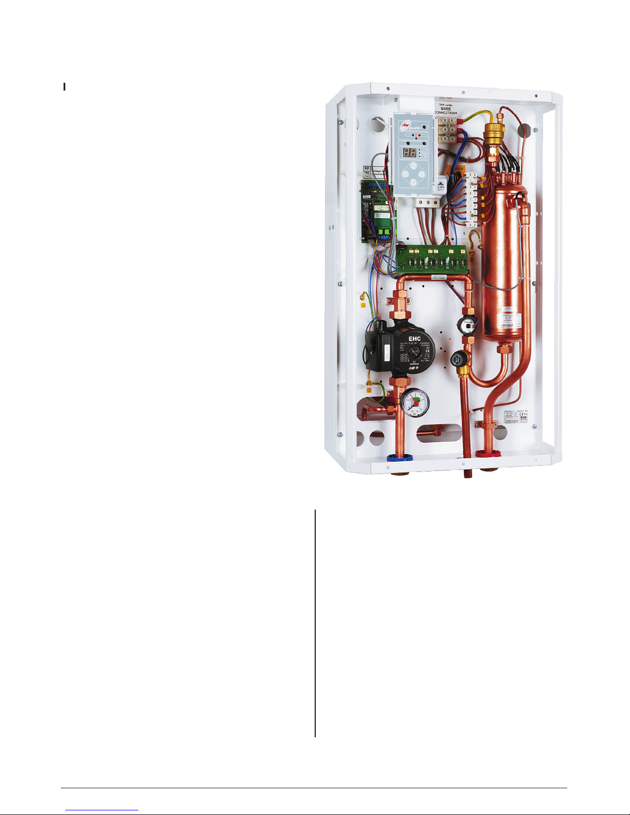
Slimline boiler
1 - heat exchanger
2 - flow sensor
3 - manometer
4 - safety valve
5 - circulating pump
6 - safety temperature limiter
7 - return inlet
8 - flow outlet
9 - ZIO board
10 - power board
11 - automatic vent
12 - control board
PF - points of electric mains connection (phases)
PN - electrical connections
L - live
PE - permanent earth
N - neutral
M -
boiler fixing positions
RP - control stat connections
Fusion boiler
1 - heat exchanger
2 - flow sensor
3 - manometer
4 - safety valve
5 - circulating pump
6 - safety temperature limiter
7 - return inlet
8 - flow outlet
9 - ZIO board
10 - power board
11 - automatic vent
12 - control board
13 - expansion vessel connection
14 - expansion vessel
PF - points of electric mains connection (phases)
PN - electrical connections
L - live
PE - permanent earth
N - neutral
M -
boiler fixing positions
RP - control stat connections
Page 13

13
f.172
that the boiler is switched on.
Page 14

14
f.172
Width 420mm
Fax:
6kW
9k
water pressure
bar
lt.
V
415V 3ph N 50Hz
240V; 25,0
Amp
Amp
Amp
Amp
415V; 33,4 Amp
Btu
40,956
Btu
49,147
Btu
40
Yes
45
Amp
Amp
Amp
40 Amp
 Loading...