

Page 1
Operating Manual
Refrigerated Compressed-Air Dryer
Air Dryer
FR005AP
FR010AP
FR020AP
FR030AP
FR050AP
FR075AP
FR100AP
FR005A
FR010A
FR020A
FR030A
FR050A
FR075A
FR100A
FR150A
Ver.071203
z This Air Dryer is designed for
industrial use. Handle with care.
z Please read this manual carefully
and operate this equipment
accordingly.
z Retain this manual for future
Reference.
Page 2

Thank you for your purchase.
Thank you for purchasing this Fu Sheng Co., Ltd product.
To ensure safe and efficient use, please install and operate this equipment in
accordance with the instructions provided in this manual.
Product specifications are subject to change without notice. Please be aware that
recent changes to product specifications may not be reflected in the content of
this manual.
CONTENTS
Important Notes........................... ........................... 1(1)
Names of Parts and Functions.......................................... 2(1)
1.Appearance..................................................
2(1)
2.Control panel................................................
2(1)
3.Switch board.................................................
3(1)
Installation Notes..................................................... 4(1)
1.Checking Model............................ ..................
4(1)
2.Space for Installation..........................................
5(1)
3.Forbidden places............................. .................
5(1)
Preparation for Operation............................................. 6(1)
1.Piping.......................................................
6(1)
2.Installation of Accessories.......................................
7(1)
3.Wiring.................................................... ....
9(1)
Operation............................................................ 10(1)
1.How to Start..................................................
10(1)
2.How to Stop..................................................
11(1)
Safety Devices.........................................................
12(1)
Daily Maintenance and Checks...........................................
13(1)
1.Daily Checks...................................................
13(1)
2.Maintenance...................... .............................
13(1)
1)Cleaning of Condenser......................................
13(1)
2)Cleaning of Auto Drain Trap(ET3000 4000)....................
14(1)
3)Cleaning of Auto Drain Trap(AD-5).............. ............
15(1)
Troubleshooting................................ .......................
16(1)
After-Sale Service....................................................
16(1)
Before Long Disuse....................................... .............
17(1)
Table of Specifications..................................................
18
Specification............................... ...........................
20
Part list.................................. ...........................
30
Page 3
Important Notes.
1(1)
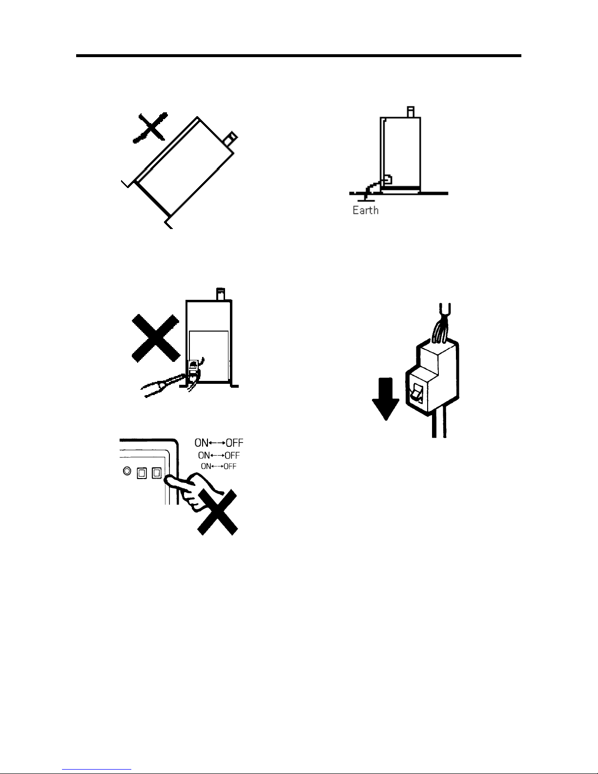
1. Do not carry the dryer turned aslant or upside
down.
3. Do not modify the wiring in the switchboard.
‧Do not modify the wiring except at the
primary-side power terminals.
5.Never turn the operation switch on and off
frequently.
2. Be sure to ground the unit to prevent electric
shock.
4.Before inspection, be sure to stop the air
compressor and turn off power to the air dryer.
Make sure that pressure is reliefed in the
air dryer.
Page 4
Names of Parts and Functions
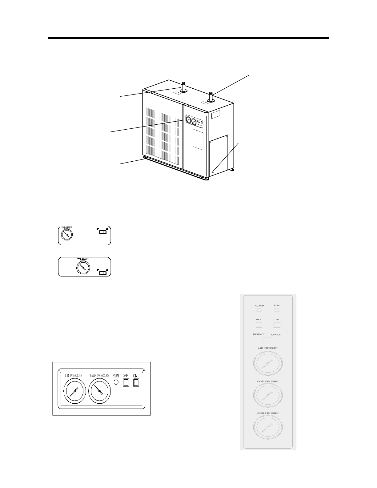
Illustrations used are those of FR020A
2 ( 1 )
1. Appearance
2. Control Panel
■ FR005A、FR005AP、FR010A、FR010AP
■ FR020A~075A、FR075AP~100AP
Air inlet
Wet compressed air inlet
Control Panel
Air Outlet
Dry compressed air outlet.
Power Cord Hole
Lead the power cord out
from here.
Leg
Use the aperture to fix
this device in place.
FR005A、FR005AP
FR010A、FR010AP
EVAP. Pressure Gauge
Indicates the EVAP. Pressure of the
Operation Switch (with lamp)
Press ON, and the lamp lights up, the dryer starts
operating. Press OFF, and the lamp goes out, the
dr
y
er stops
○6 AIR PRESSURE GAUGE
○4 START SWITCH (WHITE)
○5 REMOTE/LOCAL SWITCH
○2 RUNNING LAMP
○7 EVAP. PRESSURE GAUGE
○8 COND.PRESSURE GAUGE
○3 STOP SWITCH(RED
○1 ALARM LAMP
○1 ○2
○3 ○4
○5
○6
○7
○8
○2
○3 ○4
○6
○7
Page 5
3(1)
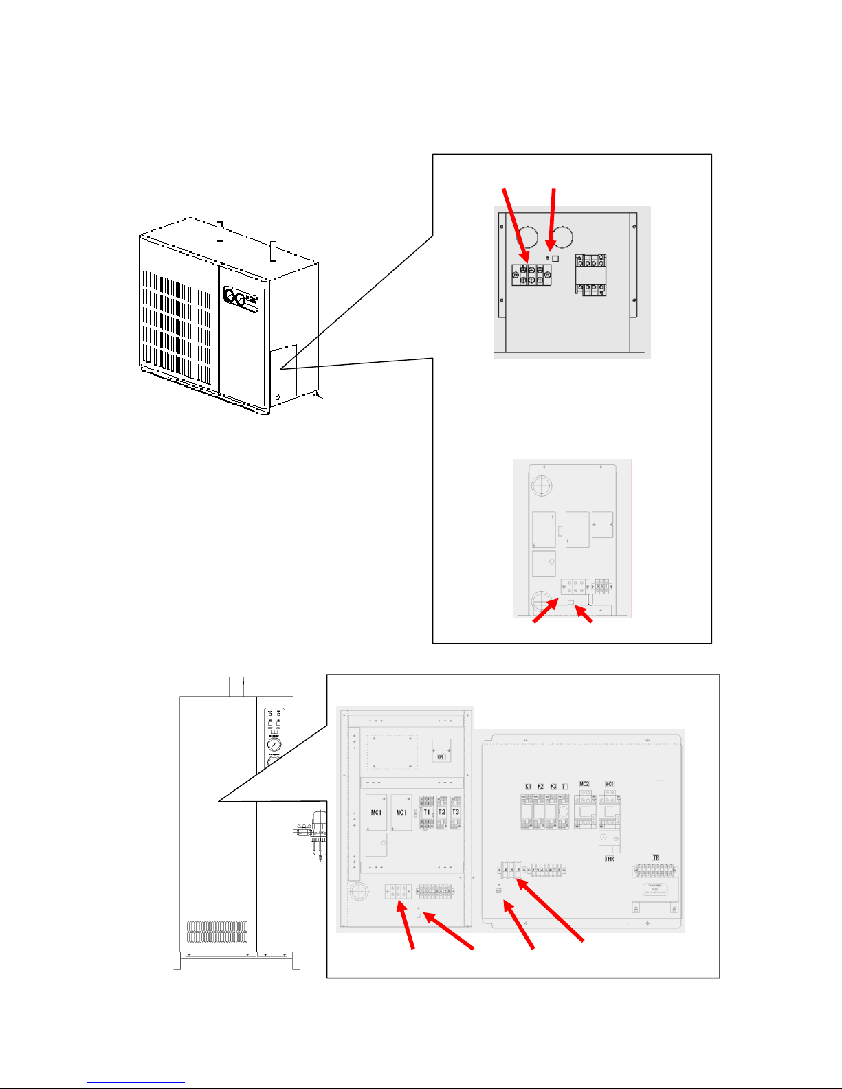
3.Switchboard
Terminal Earth
FR020AP~050AP
FR030A~075A
Terminal Earth
FR010AP
FR020A
FR100A 075AP FR150A 100AP
Terminal Earth Earth Terminal
Page 6

Installation Notes
4(1)
1. Checking Model
After unpacking the dryer, check the Specifications Plate to make sure that you have received
the system that you ordered..
■ Accessories
Auto drain trap Ball valve
FR005AP 010AP 020AP 30AP050AP
FR005A 010A 020A FR030A 050A 075A
Float type 1pc 1/2B 1pc
FR075AP 100APFR
FR100A 150A
Discus type 1pc
1/2B 1pc
Also confirm that the unit has not suffered any shipping-relating damage. In the event of a
problem, please contact your dealer
Page 7
5(1)
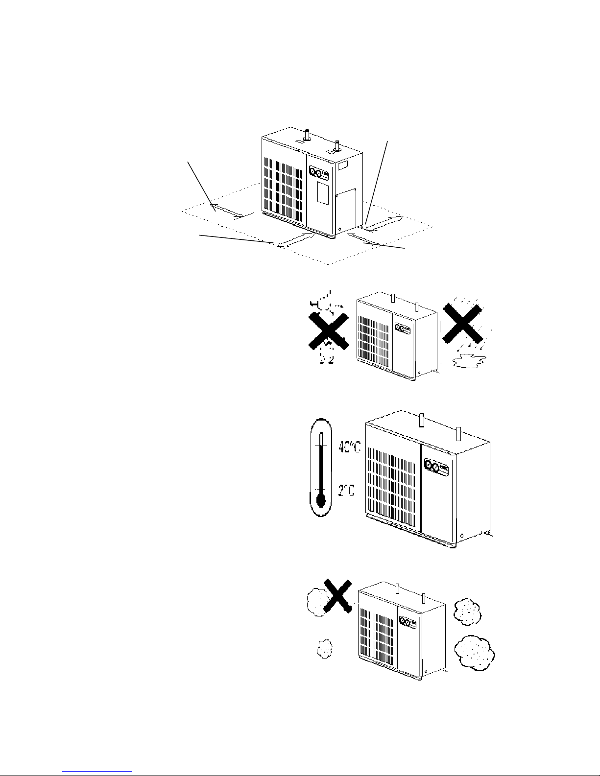
2. Space for Installation
Locate the dryer with enough free space around.
To ensure a sufficient ventilation and accessibility, keep adequate distances
between the dryer and objects in its surrounding
3. Forbidden places
■ Do not install in the place where unit will
be exposed to direct sunlight, rain, or
external heat. Such exposure may reduce
the ability of the condenser to release heat,
resulting in poor performance.
■ Ambient temperature should be between 2
℃ and 40℃. Ambient temperatures above
40℃. can impede heat release from the
condenser, resulting in safety-device
activation and equipment shutdown. If you
need to install the unit in an area where
ambient temperature may exceed 40 , set
up ductwork as necessary to supply outside
air directly to the air intake area on the
cabinet, or construct an outdoor exhaust
port to discharge the inside exhaust air
(warm air). Be sure that the design does
not result in a drop in the fan airflow.
■ Do not install in a dusty location.
Dust accumulation on the condenser may
reduce the unit’s performance
Space for ventilatio
n
60cm or more
Side space
60cm or more
Space for ventilatio
n
60cm or more
Side space
60cm or more
Page 8
Preparation for Operation
6(1)
1. Piping
■Air inlet∕outlet connection dimension
Model
FR005AP
FR010AP、015AP
020AP
FR030AP、
050AP
FR075AP FR100AP
Model
FR005A、FR010A FR020A、030A FR050A、075A FR100A FR150A
Pipesize
1/2B 1B 1-1/2B 2B 21/2B
.
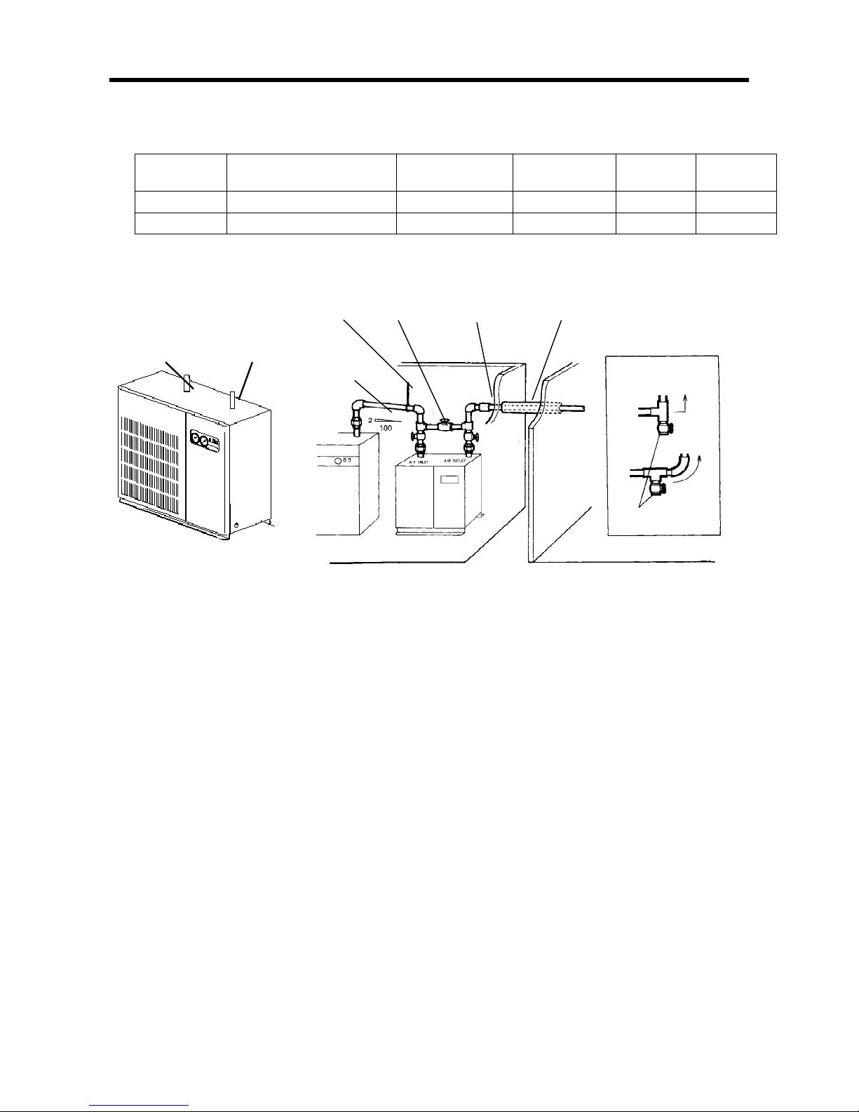
■ Piping notes
1)Do not confuse the inlet and outlet of the air dryer.
2)Do not use any riser in the piping from air compressor to air dryer.
However, if it is inevitable, install a valve or a drain trap so that water can be purged.
3)Provide a by-pass circuit between the inlet and the outlet of the air dryer.
4)Do not allow the piping weight to bear on the air dryer.
5)In a cold place, cover the outdoor piping, if any, with heat insulator.
Even indoors, use heat insulator if the air dryer outlet piping develops condensation.
6)In piping, prevent dust and other foreign materials from entering the air circuit.
AIRINLET AIROUTLET
Suspend By-pass circuit Check valve Heat Insulato
r
Inclination
Compressor Chamber
Inside
Valve or drain trap
When providing a
riser in piping
Page 9
7(1)
2. Installation of Accessories
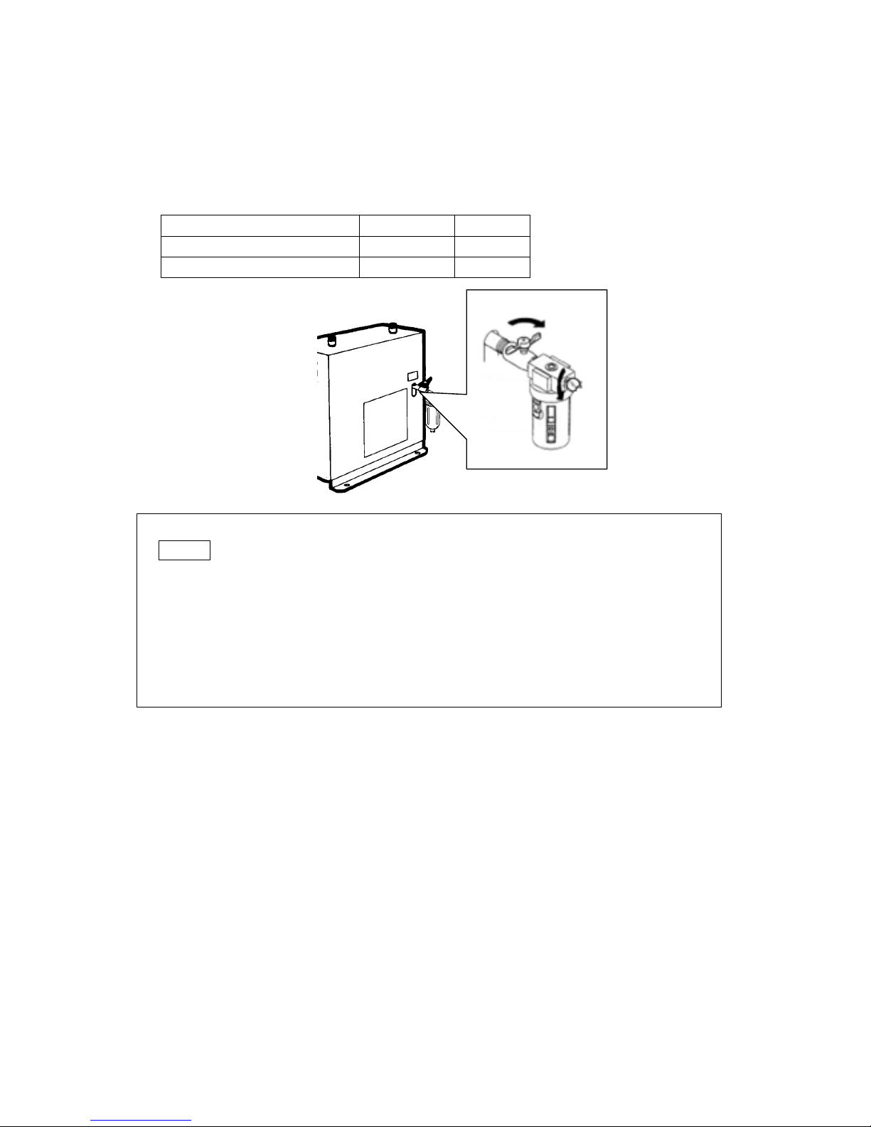
1) FR005AP、010AP、020AP、030A、050AP
FR005A、010A、020A、030A、050A、075A
■ Accessories
Auto drain trap Floattype 1pc
Ball valve 1/2B 1pc
Auto drain trap Floattype 1pc
1) As shown, install the ball valve and auto drain trap on the drain pipe with the marking
DRAIN .
2) After the installation, open the ball valve.
3) Install the auto drain trap so that the drain outlet is positioned below.
4) Use the following vinyl hose when the drainage is to be led out of the auto drain trap.
Hose inside diam.:16 mm
5) When connecting a pipe, screw it on the threaded part of the drain trap outlet.
Drain trap outlet thread diam: Rc 1/4
● Important
To remove the drain trap (when you need to replace it), proceed as follows:
(1) Close the ball valve;
(2) Release the pressurized air from the trap;
(3) Hold on to the ball valve so that it cannot turn, and rotate (unscrew) the trap to remove.
● Important
If attaching a pipe to the drain outlet, note that the pipe should not be too long and should not
move upward. Reverse pressure caused by excessive pipe length or upward flow may prevent
draining.
Page 10
8(1)
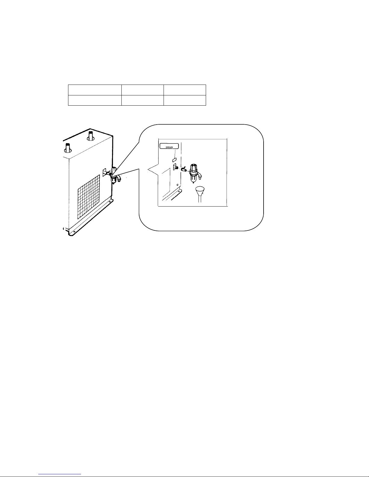
2) FR050AP、075AP、100AP
FR050A、075A、100A、150A
■ Accessories
Auto drain trap
Discus type 1 pc
Ball valve 1/2B 1 pc
● Important
To remove the drain trap (when you need to replace it), proceed as follows:
1) Close the ball valve;
2) Release the pressurized air from the trap;
3) Hold on to the ball valve so that it cannot turn, and rotate (unscrew) the trap to remove.
● Important
If attaching a pipe to the drain outlet, note that the pipe should not be too long and should not move
upward. Reverse pressure caused by excessive pipe length or upward flow may prevent draining.
Page 11
9(1)
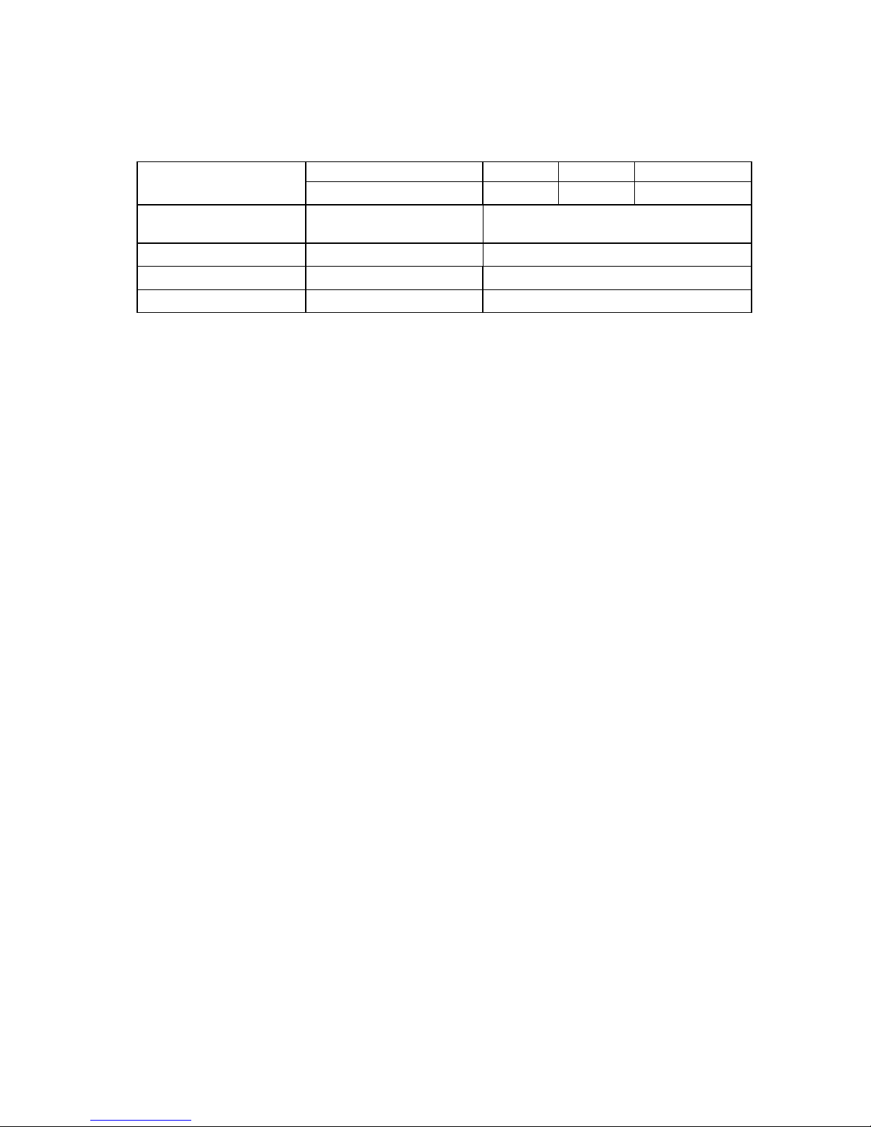
3. Electrical Wiring
1) Power-cord capacities are as follows.
Model
FR005AP、010AP、020AP FR030AP FR050AP FR075AP、100AP
FR005A、010A、020A、030A FR050A FR075A FR100A、150A
Power source
(standard type)
Single phase 220V
50/60Hz
3 phase 220V 50/60Hz
Power cord (mm2) 1.25 or more 2.0 or more
Breaker capacity (A) 10A 20A
Ground line (mm2) 1.25 or more 2.0 or more
2) Install an overload leakage breaker (overload-protect function plus current leakage
function).
The breaker must be dedicated to the air dryer. (Use high-speed type with 30mA
current sensitivity.)
3) Connect up the power cord.
For single-phase models, connect the wires to terminals 1 and 2.
For three-phase models, connect to terminals R,S and T
4) Connect the ground.
Ground (earth) connection must be set up by a qualified electrician. The ground line
must be connected to the earth terminal. The line diameter must be at least 2mm2.
5) Power voltage should remain within 5% of the rated value while the dryer is operating.
Page 12
Operation
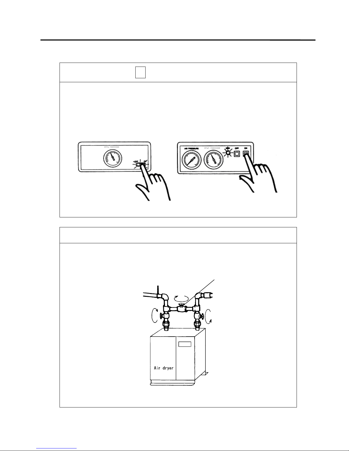
*Before starting operation, make certain that the power breaker is ON.
10(1)
1.How to start
c Press the operation switchON
The operation lamp lights up and operation starts.
FR005AP FR010AP above
FR005A、010A FR020AP
d 3 minutes later, start supplying compressed air.
About three minutes after the start of the dryer, supply compressed air by operating
the air compressor.
。
Caution At this time, be sure to close the by-pass valve in the piping。
By-pass valve
Open
Close
Open
Page 13
11(1)
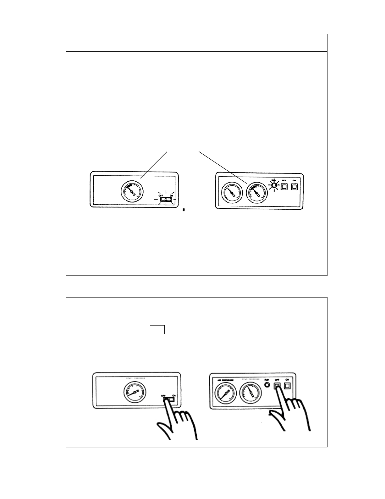
e Check the indications on the gauges.
Soon after the flow of compressed air, EVAP. pressure gauge will normally start indicating within the
green-colored range.
● EVAP. pressure gauge:
The air dryer may not easily develop trouble even when it is operated with the EVAP. pressure
gauge indicating a little beyond the green range. Yet, take care to use it within the green range
so that the dryer can perform at its maximum efficiency.
【Note】 When the ambient temperature drops, the fan may repeat stop and run operation.This is
to prevent the freezing inside the heat exchanger.
2.How to Stop
c Stop the air compressor.
d Press the stop switch OFF.
The operation lamp goes out and operation stops.
Green range
Page 14
Safety Devices
ÚThe dryer is provided with safety devices to ensure operational safety for you
12(1)
The air dryer will stop automatically at the operation of any safety device.
■ Refrigerant circuit safety device ) High-pressure switch
The high-pressure switch operates when the condensation pressure reaches:
3.0±0.1MPa (30±1kgf/cm2G) (R407CRefrigerant)
2.0 ±0.1MPa (20±1kgf/cm2G) (R134aRefrigerant)
and stops the dryer.
■ Electric circuit ) Motor protector
The motor protector will operate to stop the air dryer if the temperature of the compressor gets
high or an over current flows in the circuit.
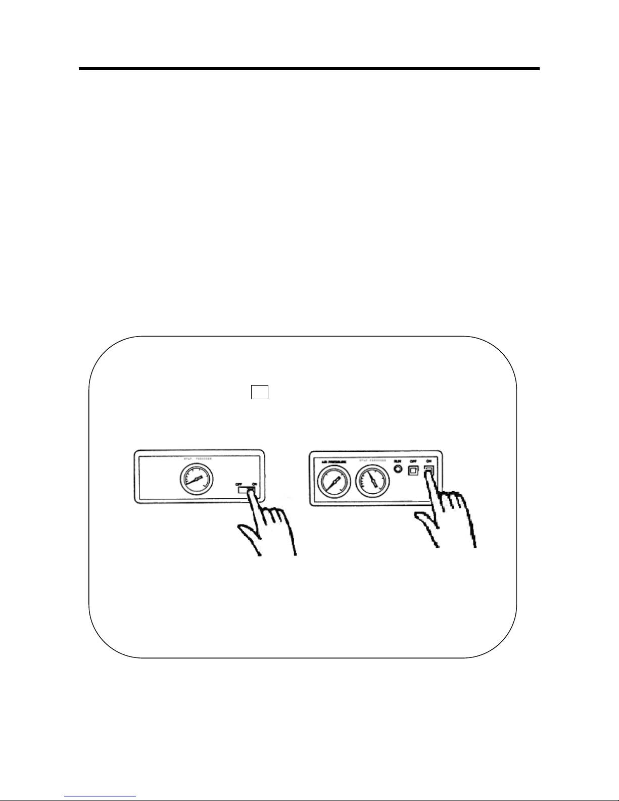
How to reset
1.Remove the cause of stoppage.(See Troubleshooting.)
2.Press the operation switch ON on the control panel.
Page 15
Daily Maintenance and Checks
13(1)
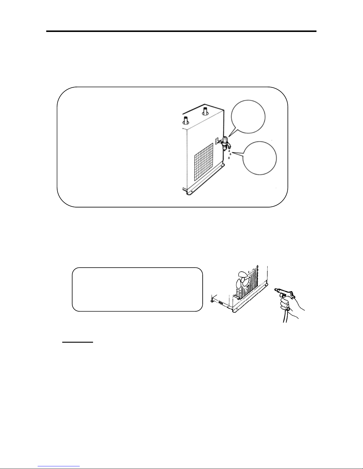
Dust or dirt accumulated on the condenser
will reduce the heat exchange efficiency.
At the worst,the dryer may stop with the
safety device operating.
1. Daily Checks
Checking of auto drain trap
Check the auto drain trap everyday.
2. Maintenance
1)Cleaning of condenser
Clean the condenser periodically, using a brush or air gun.
Caution In cleaning, exercise care so as not to deform the condenser fins.
Check items
● Air leakage
● Normal operation
(water draining)
Water
draining
No air
leakage
Page 16
14(1)
2) Cleaning of auto drain trap (Float type)
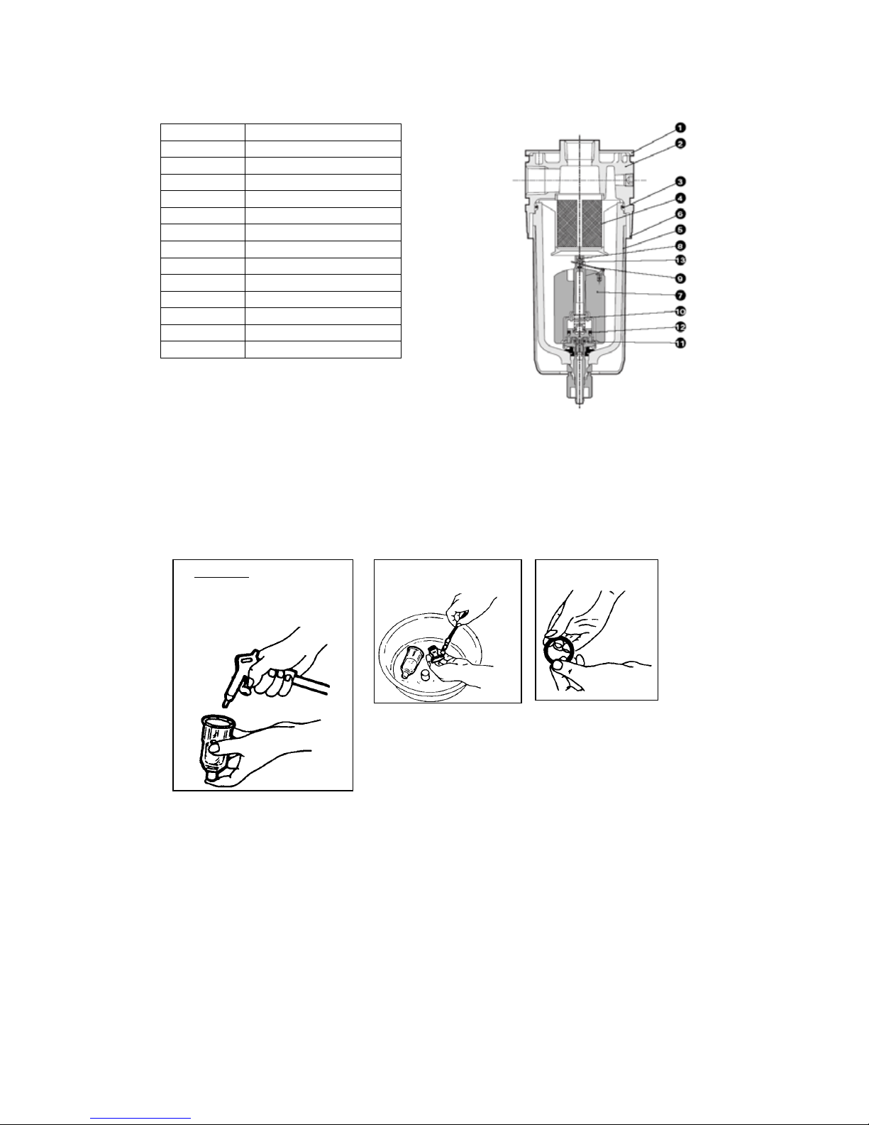
. Overhaul the auto drain trap periodically (every week) so that it can always operate normally.
NO. PARTS NAME
1
Plat cover
2
Body
3
O-ring
4
Filter
5
Bowl
6
Bowl guard
7
Float
8
Orifice
9
Float level arm
10
Spring
11
Packing
12
Valve
13
Orifice spring
■ How to clean
(1) Close the ball valve.
(2) Remove the dirt and dust from the filter element, which is fit in the lower part of the auto
drain unit, using an air gun or like means.
(3) Wash the separated parts with a neutral detergent.
(4) Check for damaged parts. Make a particularly careful check of O-ring.
(2) Caution
Neverdisassembletheauto
drainunit.Otherwise
troubleswillresult
.
(3)
(4)
● The drain should not be exposed to direct sunlight, as such exposure may damage the drain
bowl.
● The following substances can damage the drain bowl. These substances should never be
present within the drain or in the atmosphere around the drain.
○ Oils based on phosphoric acid esters.
○ Organic solvents (aromatic, chloride, and hydrocarbon compounds)
─Benzene, toluene, phenol, trichloroethylene, gasoline, paint thinner, etc.
○ Sulfurous acid gas, chorine gas, CFC gas.
○ Acids: hydrochloric acid, sulfuric acid, acetic acid, etc.
Page 17
15(1)
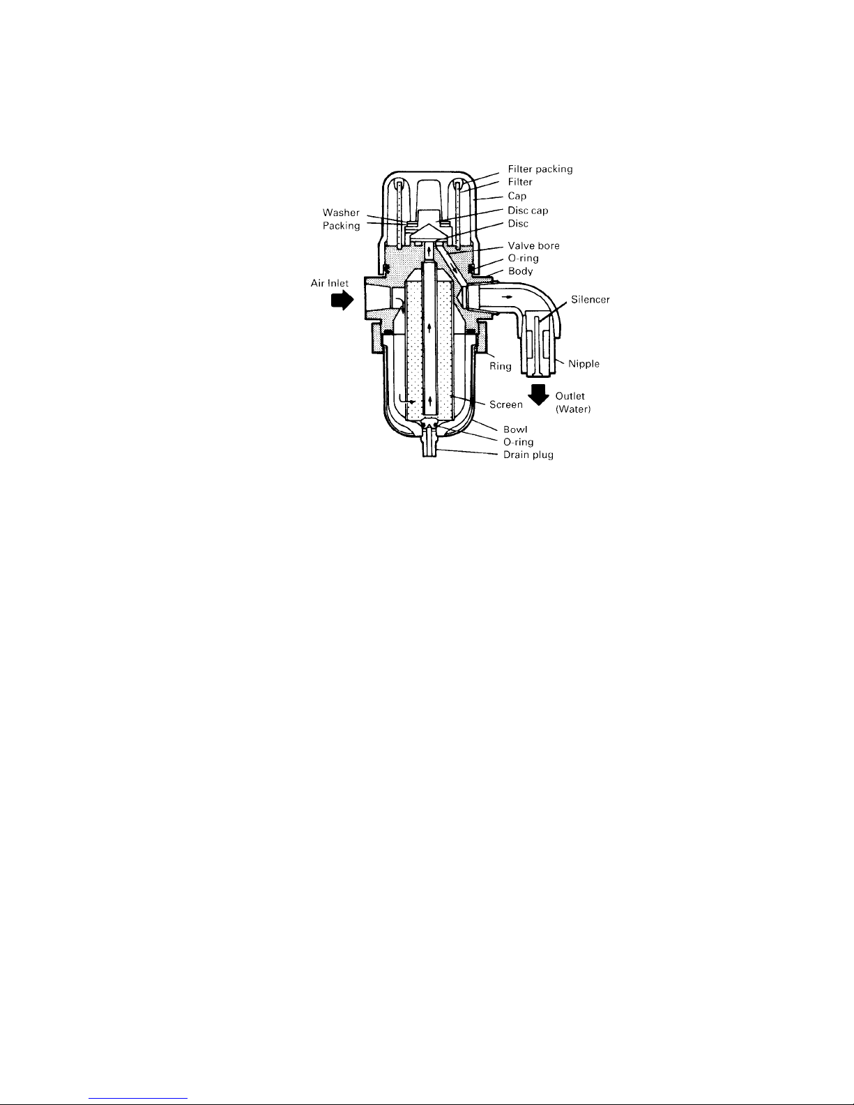
3) Cleaning of auto drain trap ( Discus type )
Overhaul the auto drain trap periodically (every week) so that it can always operate normally.
■ Parts name
■ Draining
Discharge the drainage once a week by turning the drain plug clockwise.During a
cold season, perform the drainage after every operation to prevent freezing.
■ Draining before a long suspension of operation.
Be sure to discharge the water from the bowl by turning "clockwise" the drain plug
at the bottom of the drain trap.
■ Adjustment of drainage discharge
The operating interval of this drain trap varies with the load, pressure,etc.
Turning the needle valve in the "+"direc tion will shorten the interval and increase
the drainage discharge.Adjust the interval in such a way that water will not
accumulate in the bowl.
■ Disassembly
If some abnormality, such as excessive dirt on the screen or longer interval, is found,
overhaul the drain trap as follows:
Turn the cap counterclockwise and remove it .
Blow the dust off from the filter, using compressed air.
Clean the disc cap and disc.
Turn the ring counterclockwise and remove it.
Remove the screen.
Blow the dust off the screen.
Wash the bowl with a neutral detergent. Never use any organic solvent.
Check all the parts for damage. Never fail to check the O-rings, packings and washer
Page 18

Troubleshooting
16(1)
■ Should any trouble arise during operation of the dryer, correct it using the troubleshooting chart
below
Problem Possible Cause Solution
Dryer does not operate with
operation switch ON
pressed.
(RUN lamp does not light up.)
‧Lamp disconnected
‧Switch faulty
‧Low power supply voltage
‧Magnetic contactor faulty
‧Protector faulty
‧High pressure switch faulty
‧Replace.
‧Replace.
‧Use specified voltage.
‧Replace.
‧Replace.
‧Replace.
Dryer does not operate with
operation switch ON pressed
(RUN lamp lights up.)
‧Magnetic contactor faulty
‧Protector fault
‧Replace.
‧Replace
Dew point is normal but
water or oil drops occur.
‧Drainage hindered by foreign
material in auto drain trap
‧Drainage in auto drain trap frozen
‧Disassemble and clean
auto drain trap.
‧Take proper measures to
prevent freezing.
Dew point is high and water
or oil drops occur.
‧ Too high air processing rate
‧Lowered cooling capacity
‧Condenser clogged up
‧Too high ambient temperature
‧Fan motor faulty
‧Correct air processing
rate.
‧Check for gas leak.
‧Clean.
‧Lower ambient
temperature.(below 40
℃)
‧Replace.
Machine stops suddenly
during operation.
‧Magnetic contactor faulty
‧Too high air processing rate
‧Condenser clogged up
‧Too high ambient temperature
‧Abnormal voltage
‧Fan control pressure switch faulty
‧Replace.
‧Correct air processing
rate.
‧Clean
‧Lower ambient
temperature. (below 40
℃)
‧Use rated voltage.
‧Replace.
After -Sale Service
■ Should any trouble arise, correct it according to the troubleshooting chart. If you can not
correct it, contact your dealer and ask for the repair. When you request an after-sale service on
the dryer, give information on the following particulars:
● Application for repair
(1) Model and Serial No.of the air dryer
(2) Defective part and trouble
(3) Date of purchase
(4) Sketch map of your location
● Application for parts
(1) Model and Serial No.of the dryer
(2) Number, name and quantity of part(s)
Page 19
Before Long Disuse
17(1)
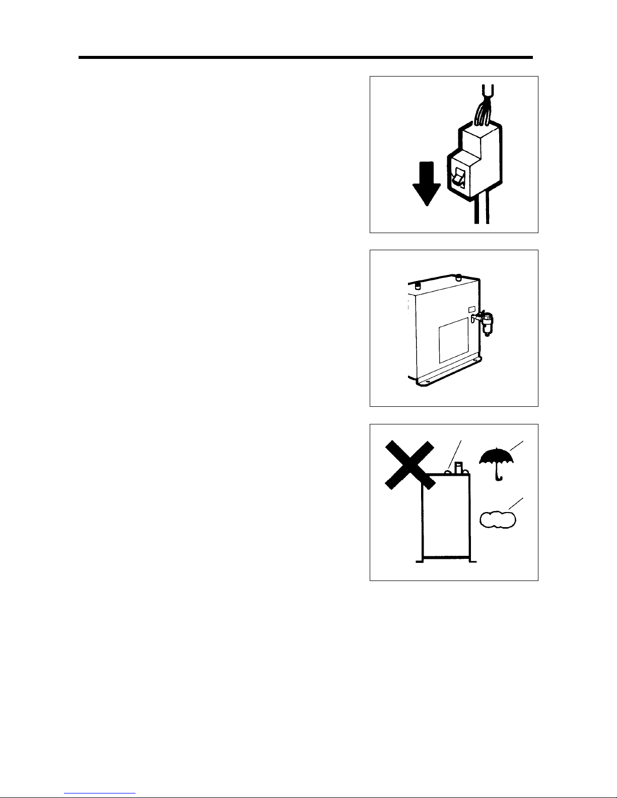
1. Turn off the power
Turn off the main power supply(power supply
breaker).
2. Purge drainage out
Discharge the drainage inside the air dryer
completely through the auto drain trap.
3. Store
Store the air dryer in a place free from dirt,
dust, rain, water, snow, etc.
■ For operation after a long disuse
Perform checks of the parts of the air dryer. Then resume operation according to the
instructions on preparation and operation in this manual.
Page 20
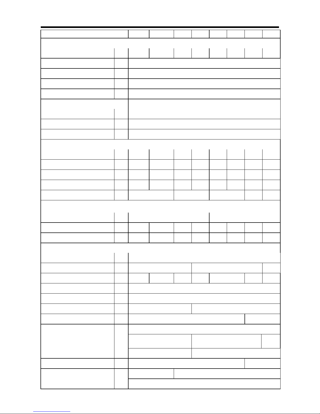
Table of Specifications
規格表
18
Model機型 FR 005A 010A 020A 030A 050A 075A 100A 150A
Measurement conditions on air processing
處理空氣條件
Air processing capacity
空氣處理量
m3/ min 0.6 1.2 2.4 4.4 7.0 11.0 14.0 23.5
Inlet air pressure
入口空氣壓力
MPa 0.69
Inlet air temperature
入口空氣溫度
℃ 35
Dew point of outlet air
出口空氣露點
℃
-17 at atmosphere
大氣壓下 17
Ambient temperature
環境溫度
℃ 32
Allowable conditions
使用範圍
Maximum inlet air temperature
最高使用溫度
℃ 10 ~ 50
Ambient temperature
環境溫度
℃ 2 ~ 40
Maximum air pressure
最高使用壓力
MPa 0.2 ~ 0.98
External dimensions
本體外形尺寸
Height
高度
mm 478 542 705 705 966 1166 1220 1260
Depth
深度
mm 490 423 423 440 490 490 984 1022
Width
寬度
mm 377 722 797 797 944 944 696 792
Net weight
淨重
kg 22 34 42 42 70 88 105/95 180
Air pipe connection
空氣配管尺寸
B R 1/2 R 1 R 1-1/2 R 2 R 2-1/2
Electric rating
電氣規格
Power source
使用電源
1ø220V 50/60Hz
單相 220V 50/60Hz
3ø220V50/60Hz
三相 220V50/60Hz
Power consumption
消耗電力
kW 0.25/0.3 0.4/0.5 0.6/0.7 0.8/0.9 1.6/1.7 1.6/1.7 2.2/1.7 3.4/4.1
Electric current
電流
A
1.3/1.5 2.0/2.3 2.7/3.3 4.1/4.5 6.0/6.7 6.3/7.5 8.0/6.8 12.0/12.5
Equipment details
裝置細目
Evaporator
熱交換器
Cross - wave fin type (Shell : SUS304)
交錯氣流鰭片 (外殼材質:SUS304)
Condenser
冷凝器
Fin and tube, forced air cooling
鰭管式,強迫通風
Parallel flow condenser ,forced air cooling
平行流風扇強制通風
Fin and tube
鰭管式
Fan motor for condenser
冷凝器用風扇馬達
φ/W 120/40 230/40 250/40 300/40 350/100 400/250 500/400
Refrigerant controller
冷媒控制
Capillary tube system
毛細管
Capacity controller
容量控制
Capacity control valve
容量控制閥
Refrigerant
冷媒
R134a R407C
Auto drain trap
自動排水器
Float type
浮球式
Discus type
碟式
Protecting devices
保護裝置
Over current relay
過電流保護繼電器
─
Opposite phase relay
反相繼電器
Compressor
壓縮機
─
Thermostat
過熱繼電器
Fan motor for condenser
冷凝器用風扇馬達
─
Fan motor over temp. switch
風扇馬達過熱保護開關
Refrigerant circuit
冷媒回路
─
High pressure switch
高壓壓力開關
Cooling fan control switch
風扇控制壓力開關
Page 21
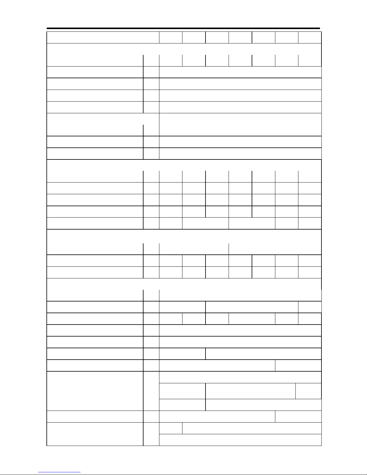
Table of Specifications
規格表
19
Model
機型
FR 005AP 010AP 020AP 030AP 050AP 075AP 100AP
Measurement conditions on air processing
處理空氣條件
Air processing capacity
空氣處理量
m3/ min 0.6 1.2 2.4 4.4 7.0 11.0 14.0
Inlet air pressure
入口空氣壓力
MPa 0.69
Inlet air temperature
入口空氣溫度
℃ 55
Dew point of outlet air
出口空氣露點
℃
-17 at atmosphere
大氣壓下 17
Ambient temperature
環境溫度
℃ 32
Allowable conditions
使用範圍
Maximum inlet air temperature
最高使用溫度
℃ 10 ~ 80
Ambient temperature
環境溫度
℃ 2 ~ 40
Maximum air pressure
最高使用壓力
MPa 0.2 ~ 0.98
External dimensions
本體外形尺寸
Height
高度
mm 542 705 705 966 1166 1214/1220 1260
Depth
深度
mm 423 423 440 490 490 1022/973 1022
Width
寬度
mm 722 797 797 944 944 792/670 792
Net weight
淨重
kg 34 42 42 70 88 175/105 180
Air pipe connection
空氣配管尺寸
B R1/2 R1 R1-1/2 R2 R2-1/2
Electric rating
電氣規格
Power source
使用電源
1 phase 220V 50/60Hz
單相 220V 50/60Hz
3phase220V50/60Hz
三相 220V50/60Hz
Power consumption
消耗電力
kW 0.4/0.5 0.6/0.7 0.8/0.9 1.6/1.7 1.6/1.7 3.4/2.6 3.8/4.1
Electric current
電流
A
2.0/2.3 2.7/3.3 4.1/4.5 6.7/7.0 6.7/7.7 12/7.5 12.0/12.5
Equipment details
裝置細目
Evaporator
熱交換器
Cross - wave fin type (Shell : SUS304)
交錯氣流鰭片 (外殼材質:SUS304)
Condenser
冷凝器
Fin and tube, forced air cooling
鰭管式,強迫通風
Parallel flow condenser ,forced air cooling
平行流風扇強制通風
Fin and tube
鰭管式
Fan motor for condenser
冷凝器用風扇馬達
φ/W 230/40 250/40 300/40 350/100
500/400
400/250
500/400
Refrigerant controller
冷媒控制
Capillary tube system
毛細管
Capacity controller
容量控制
Capacity control valve
容量控制閥
Refrigerant
冷媒
R134a R407C
Auto drain trap
自動排水器
Float type
浮球式
Discus type
蝶式
Protecting devices
保護裝置
Over current relay
過電流保護繼電器
─
Opposite phase relay
反相繼電器
Compressor
壓縮機
─
Thermostat
過熱繼電器
Fan motor for condenser
冷凝器用風扇馬達
─
Fan motor over temp. switch
風扇馬達過熱保護開關
Refrigerant circuit
冷媒回路
─
High pressure switch
高壓壓力開關
Cooling fan control switch
風扇控制壓力開關
Page 22
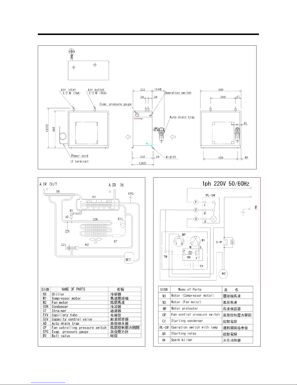
Specifications 規格
【FR005A】
20
■ Overall Dimensions(unit : mm)
■ Circuit Diagram ■ Wiring Diagram
Page 23
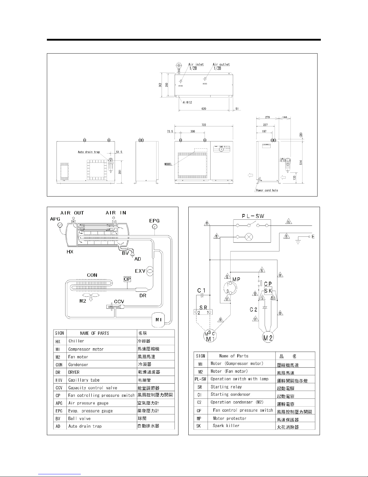
【FR005AP FR010A】
21
■ Overall Dimensions(unit : mm)
■ Circuit Diagram ■ Wiring Diagram
Page 24
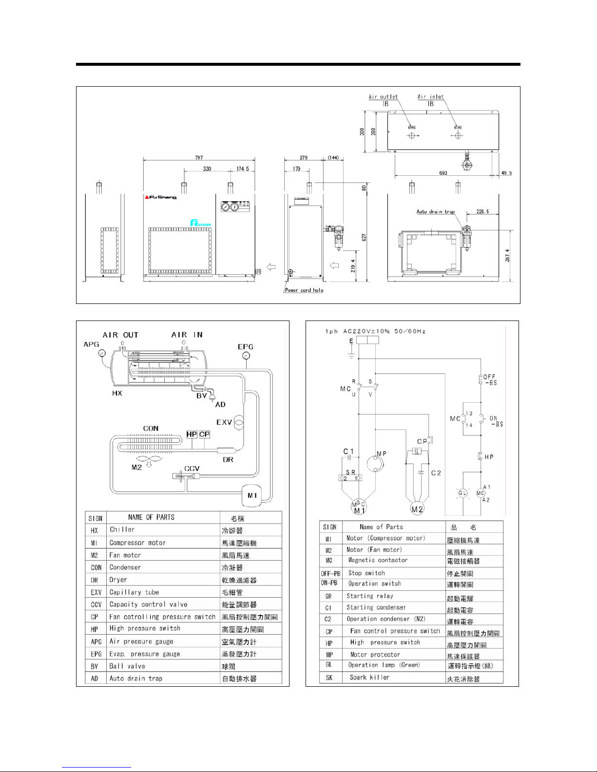
【FR010AP FR020A】
22
■ Overall Dimensions(unit : mm)
■ Circuit Diagram ■ Wiring Diagram
Page 25
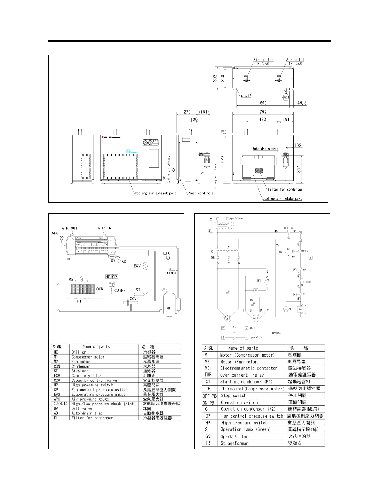
【FR020AP FR030A】
23
■ Overall Dimensions(unit : mm)
■ Circuit Diagram ■ Wiring Diagram
Page 26
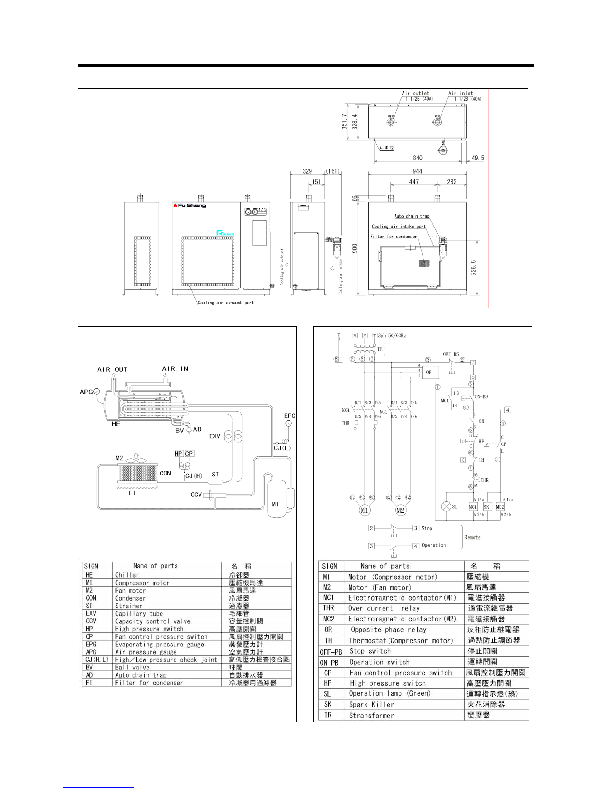
【FR030AP FR050A】
24
■ Overall Dimensions(unit : mm)
■ Circuit Diagram ■ Wiring Diagram
Page 27
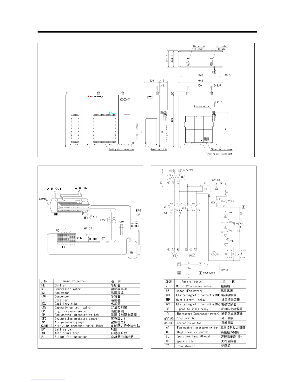
【FR050AP FR075A】
25
■ Overall Dimensions(unit : mm)
■ Circuit Diagram ■ Wiring Diagram
Page 28
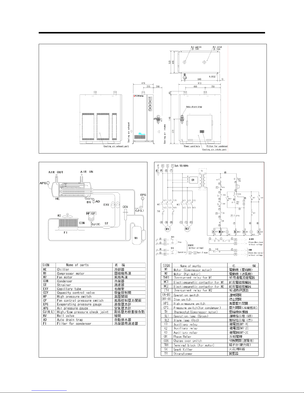
【FR100A】60Hz
26
■ Overall Dimensions(unit : mm)
■ Circuit Diagram ■ Wiring Diagram
Page 29

【FR075AP60Hz FR100A50Hz】
27
■ Overall Dimensions(unit : mm)
■ Circuit Diagram ■ Wiring Diagram
Page 30
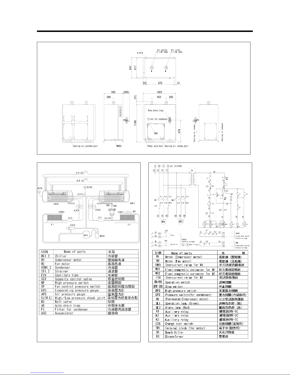
【FR100AP FR150A】
28
■ Overall Dimensions(unit : mm)
■ Circuit Diagram ■ Wiring Diagram
Page 31
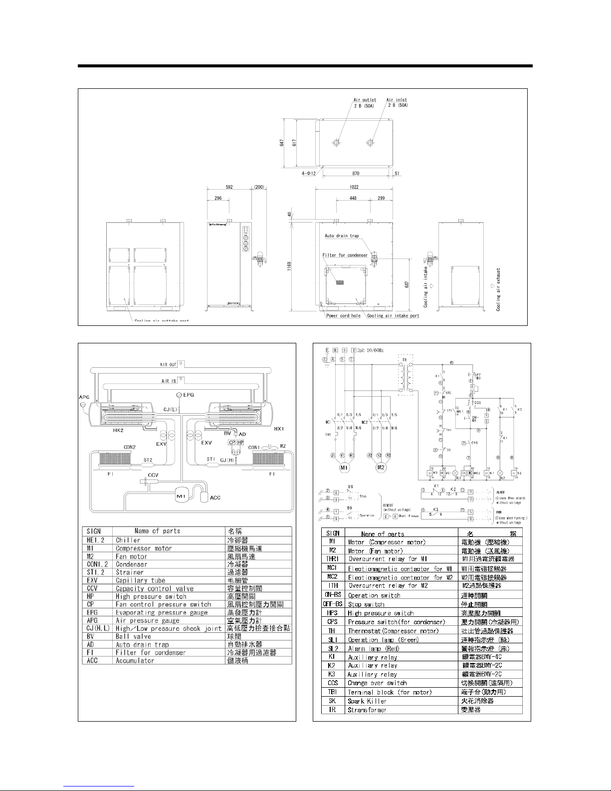
【FR075AP50Hz】
29
■ Overall Dimensions(unit : mm)
■ Circuit Diagram ■ Wiring Diagram
Page 32
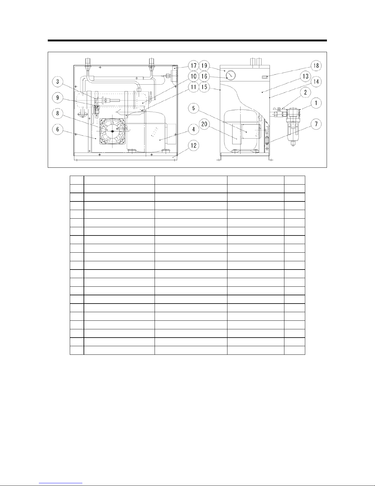
PARTS LIST 零件表
FR005A
30
No. PART NAME 部品名稱 SPECIFICATION Q'TY
1 AUTO DRAIN TRAP 自動排水器 DT3000 1
2 BALL VALVE 球閥 111TP 1
3 CAPACITY CONTROL VALVE
熱旁通閥
CGX-2315DM 1
4 BARE COMPRESSOR
壓縮機本體
GL45TG 1
5 MOTOR PROTECTOR
馬達保護器
MRA-5758 1
6 HOOD
風扇護框
1
7 CONDENSER
冷凝器
1X8X240 1
8 FAN
風扇
S109AP-11-1 1
9 FAN CONTROL
風扇控制壓力開關
ACB-0905 1
10 HEAT EXCHANGER 熱交換器 RAX-3B 1
11 REFRIGERANT STRAINER
冷媒過濾器
9G 1
12 BASE
底座
LGHC 1
13 PANEL 本体 EGC-B 1
14 RIGHT SIDE PANEL 右側板 EGC-B 1
15 LEFT SIDE PANEL 左側板 EGC-B 1
16 PRESSURE GAUGE 50
50 壓力錶
6123-0900-00 1
17 GAUGE FITTING
錶固定金具
LGHC 1
18 CORRUGATED SWITCH 波形按鍵開關 3035-POT2B01RDBK 1
19 OPERATION PLATE FILM
操作面板貼紙
TETRONIC FILM 1
20 RUNNING CAPACI TOR 運轉電容器 47MF 1
Page 33
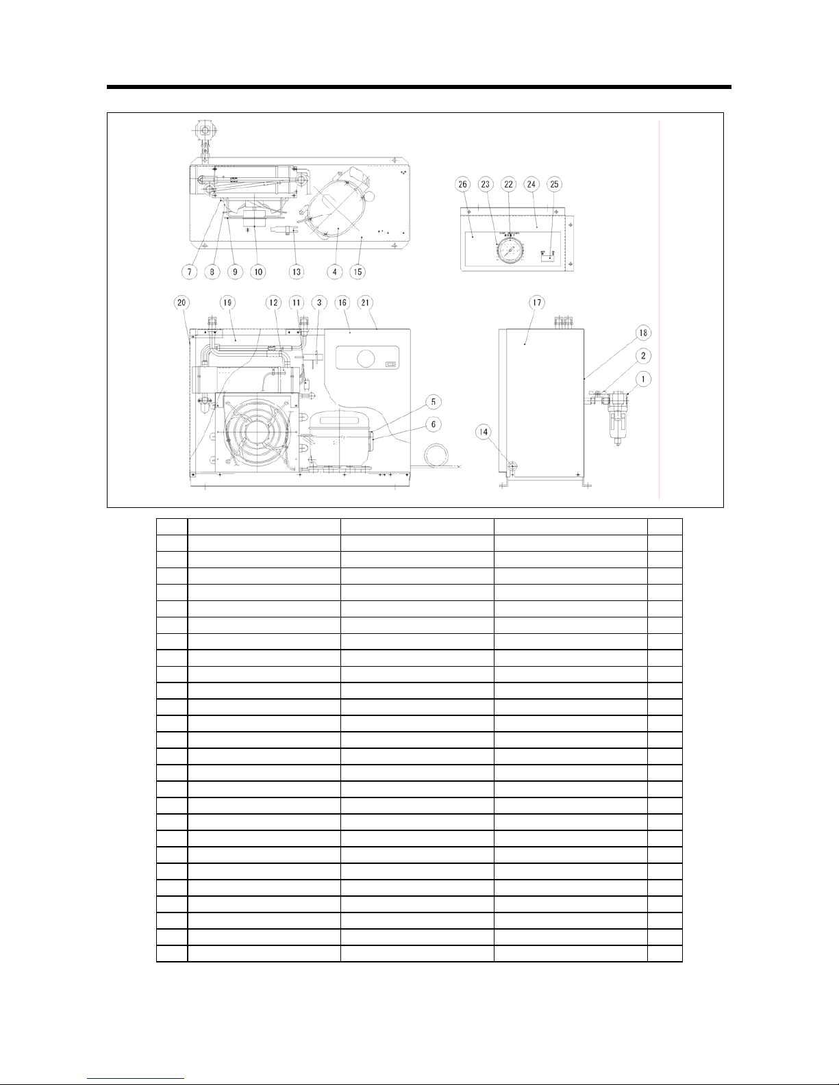
FR005AP FR010A
31
No. PART NAME 部品名稱 SPECIFICATION Q'TY
1 AUTO DRAIN TRAP 自動排水器 DT3000 1
2 BALL VALVE 球閥 111TP 1
3 CAPACITY CONTROL VALVE 熱旁通閥 CGX-2315DM 1
4 BARE COMPRESSOR 壓縮機本體 AEZ4430Y 1
5 MOTOR PROTECTOR 馬達保護器 MRT56AMK 1
6 STARTING RELAY 起動繼電器 0012-45 437 1
7 CONDENSER 冷凝器 2-10-245-O 1
8 FAN 風扇 230D (9") 1
9 FAN GUARD 風扇固定架 230D (9") 1
10 MOTOR 風扇馬達 12" 1
11 FAN CONTROL 風扇控制壓力開關 ACB-0905 1
12 HEAT EXCHANGER 熱交換器 RAX-6B 1
13 REFRIGERANT STRAINER 冷媒過濾器 9G 1
14 BUSH 線套 φ20 1
15 BASE 底座 LGHC 1
16 RIGHT FRONT PANEL 右前板 EGC-B 1
17 RIGHT SIDE PANEL 右側板 EGC-B 1
18 REAR PANEL 後板 EGC-B 1
19 LEFT FRONT PANEL 左前板 EGC-B 1
20 LEFT SIDE PANEL 左側板 EGC-B 1
21 UPPER PANEL 上板 EGC-B 1
22 PRESSURE GAUGE 50 50 壓力錶 6123-0900-00 1
23 GAUGE FITTING 錶固定金具 LGHC 2.3T 1
24 CONTROL PANEL 操作面板 EGC-B 1
25 CORRUGATED SWITCH 波形開關 3036-POT2801ROBK 1
26 OPERATION PLATE FILM 操作面板貼紙 TETRONIC FILM 1
Page 34
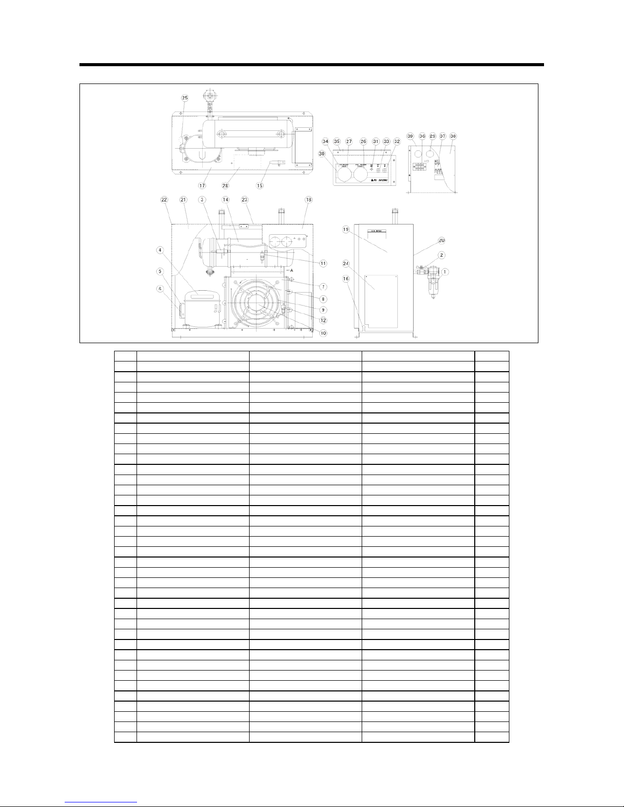
FR010AP FR020A
32
No. PART NAME 部品名稱 SPECIFICATION Q'TY
1 AUTO DRAIN TRAP 自動排水器 DT3000 1
2 BALL VALVE 球閥 111TP 1
3 CAPACITY CONTROL VALVE 熱旁通閥 CGX-2315DM 1
4 BARE COMPRESSOR 壓縮機本體 CAE4440Y 1
5 MOTOR PROTECTOR 馬達保護器 MRP36AMK 1
6 STARTING RELAY 起動繼電器 5645 514 1
7 CONDENSER 冷凝器 3-11-330-O 1
8 FAN 風扇 250D (10") 1
9 FAN GUARD 風扇固定架 250D (10") 1
10 MOTOR 風扇馬達 12" 1
11 FAN CONTROL 風扇控制壓力開關 ACB-0905 1
12 HIGH PRESSURE SWITCH 高壓壓力開關 DB92 1
14 HEAT EXCHANGER 熱交換器 1
15 REFRIGERANT STRAINER 冷媒過濾器 1
16 BUSH 線套 φ20 1
17 BASE 底座 LGHC 1
18 RIGHT FRONT PANEL 右前板 EGC-B 1
19 RIGHT SIDE PANEL 右側板 EGC-B 1
20 REAR PANEL 後板 EGC-B 1
21 LEFT FRONT PANEL 左前板 EGC-B 1
22 LEFT SIDE PANEL 左側板 EGC-B 1
23 UPPER PANEL 上板 EGC-B 1
24 SWITCH BOARD COVER 配電盤蓋 EGC-B 1
25 STARTING CAPACITOR 起動電容器 64MF 1
26 PRESSURE GAUGE 50 50 壓力錶 6123-0900-00 1
27 PRESSURE GAUGE 50 50 壓力錶 M500-04-2084 1
29 BUSH 線套 φ30 2
30 FIXED METAL A 錶固定金具 LGHC 2.3T 1
31 PILOT LAMP 指示燈 NB-281PGF AC220V 1
32 PUSH BUTTON SWITCH 按鍵開關 P13-1B(WHITE) 1
33 PUSH BUTTON SWITCH 按鍵開關 P13-1C(RED) 1
34 OPERATION PLATE FILM 操作面板貼紙 TETRONIC FILM 1
35 CONTROL PANEL 操作面板 EGC-B 1
36 TERMINAL BLOCK 端子台 TB112F 3P 1
37 MAGNETIC CONTACTOR 電磁接觸器 S-C11 AC220V 1
38 SWITCHBOARD HOOD 配電盤蓋 1
39 SWITCHBOARD BASE 配電盤底座 EGC-B 1
Page 35
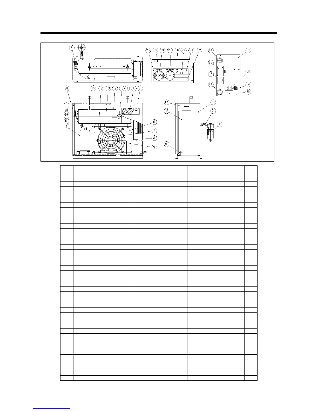
FR020AP FR030A
33
No. PART NAME 部品名稱 SPECIFICATION Q'TY
1 AUTO DRAIN TRAP ASSY. 自動排水器 DT4000 1
2 BALL VALVE 球閥 1/2" T201-04BTP 1
3 CAPACITY CONTROL VALVE 熱旁通閥 SPX-4540DH 1
4 BARE COMPRESSOR 壓縮機本體 KE-C122QZ (1φ,220V 50/60Hz) 1
5 THERMOSTAT 過熱防止調節器 1NT001L-4663 1
6 CONDENSER 冷凝器 0A00048720(PC114) 1
7 FAN 風扇 300D (12") (50,75,100)(6 片) 1
8 FAN GUARD 風扇固定架 300D (12") (50,75,100) 1
9 MOTOR 風扇馬達 KAF12142 (1φ,220V 50/60Hz) 1
10 FAN CONTROL 風扇控制壓力開關 ACB-2114A 1
11 HIGH PRESSURE SWITCH 高壓壓力開關 ACB-2330 1
12 REFRIGERANT STRAINER 冷媒過濾器 1/4”×1/4" φ2.4 (φ18.85×t0.7) 1
13 HEAT EXCHANGER 熱交換器 02090149040 RAX22F 1
14 BUSH 線套 φ30 2
15 BASE 底座 LGHC 1
16 RIGHT FRONT PANEL 右前板 EGC-B 1
17 RIGHT SIDE PANEL 右側板 EGC-B 1
18 REAR PANEL 後板 EGC-B 1
19 LEFT FRONT PANEL 左前板 EGC-B 1
20 LEFT SIDE PANEL 左側板 EGC-B 1
21 UPPER PANEL 上板 EGC-B 1
22 SWITCH BOARD COVER 配電盤外蓋 EGC-B 1
23 PRESSURE GAUGE 50 50 壓力錶 0-1.5MPa 1
24 PRESSURE GAUGE 50 50 壓力錶 6123-0914-00 1
25 FIXED METAL A 錶固定金具 LGHC 2.3T 1
26 PILOT LAMP 指示燈 NB-281PGF AC220V 1
27 RUNNING CAPACITOR 運轉電容器 17μF400VAC 1
28 ON-PUSH BUTTON SWITCH 按鍵開關 P13-1B (WHITE) 1
29 OFF-PUSH BUTTON SWITCH 按鍵開關 P13-1C (RED) 1
30 STARTING CAPACITOR 起動繼電器 0
31 STARTING RELAY 起動電容器 14.7uF 1
32 OPERATION PLATE FILM 操作面板貼紙 TETRONIC FILM 0.125T 1
33 CONTROL PANEL 操作面板 EGC-B 1
34 TERMINAL BLOCK 端子台 TB112F 3P 1
35 MAGNETIC CONTACTOR 電磁接觸器 S-C12D10G7 (220V) 1
36 SWITCHBOARD HOOD 配電盤蓋 1
37 SWITCHBOARD BASE 配電盤底座 EGC-B 1
38 TERMINAL BLOCK 卡式端子台 TB112F 3P 25A 1
39 SWITCHBOARD FIXED METAL 配電盤固定金具 EGC-B 1
40 CABLE CONNECTOR 電纜固定頭
φ
20 1
Page 36
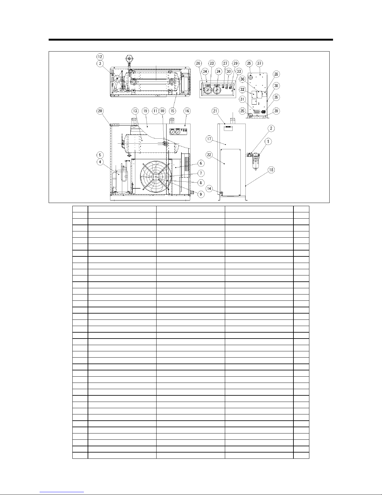
FR030AP FR050A
34
No. PART NAME 部品名稱 SPECIFICATION Q'TY
1 AUTO DRAIN TRAP ASSY. 自動排水器 DT4000 1
2 BALL VALVE 球閥 1/2" T201-04BTP 1
3 CAPACITY CONTROL VALVE 熱旁通閥 SPX-4540DH 1
4 BARE COMPRESSOR 壓縮機本體 KFPC262QZFC-F(3φ220V 50/60Hz) 1
5 THERMOSTAT 過熱防止調節器 1NT001L-4663 1
6 CONDENSER 冷凝器 0A000489010(PC115) 1
7 FAN 風扇 350D (14") 1
8 FAN GUARD 風扇固定架 350D (14") 1
9 MOTOR 風扇馬達 YWF-4D-350D(14") 1
10 FAN CONTROL 風扇控制壓力開關 ACB-2114A 1
11 HIGH PRESSURE SWITCH 高壓壓力開關 ACB-2330 1
12 COPPER PIPE STRAINER 銅管過濾器 FS1033-35(3/8") 1
13 HEAT EXCHANGER 熱交換器 02090342030 (RAX37F) 1
14 CABLE CONNECTOR 電纜固定頭
φ
20 1
15 BASE 底座 LGHC 1
16 RIGHT FRONT PANEL 右前板 EGC-B 1
17 RIGHT SIDE PANEL 右側板 EGC-B 1
18 REAR PANEL 後板 EGC-B 1
19 LEFT FRONT PANEL 左前板 EGC-B 1
20 LEFT SIDE PANEL 左側板 EGC-B 1
21 UPPER PANEL 上板 EGC-B 1
22 SWITCH BOARD COVER 配電盤外蓋 EGC-B 1
23 PRESSURE GAUGE 50 50 壓力錶 0-1.5MPa 1
24 PRESSURE GAUGE 50 50 壓力錶 6123-0914-00 1
25 BUSH 線套
φ
30 2
26 FIXED METAL A 錶固定金具 LGHC 2.3T 1
27 PILOT LAMP 指示燈 NB-281PGF AC220V 1
28 Opposite phase relay 反向防止繼電器 APR-3 1
29 PUSH BUTTON SWITCH 按鍵開關 P13-1B(WHITE) 1
30 PUSH BUTTON SWITCH 按鍵開關 P13-1C(RED) 1
31 TERMINAL BLOCK 端子台 TB112F 3P 25A 1
32 ELECTROMAGNETIC CONTACTOR 電磁開閉器 MSO-C12 220V NTH-11 11A 1
33 OPERATION PLATE FILM 操作面板貼紙 TETRONIC FILM 1
34 CONTROL PANEL 操作面板 EGC-B 1
35 TERMINAL BLOCK 卡式端子台 NHC-10-3P 1
36 MAGNETIC CONTACTOR 電磁接觸器 S-C11 220V 1
37 SWITCHBOARD HOOD 配電盤 EGC-B 1
38 SWITCHBOARD BASE 配電盤底座 EGC-B 1
39 SWITCHBOARD FIXED METAL 配電盤固定金具 EGC-B 1
Page 37
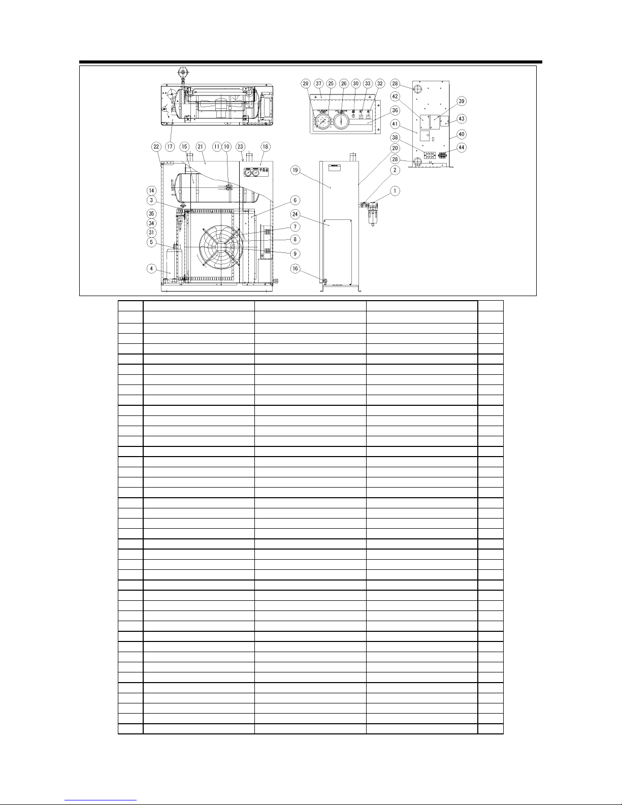
FR050AP FR075A
35
No. PART NAME 部品名稱 SPECIFICATION Q'TY
1
AUTO DRAIN TRAP ASSY. 自動排水器
DT4000
1
2 BALL VALVE 球閥 1/2" T201-04BTP 1
3 CAPACITY CONTROL VALVE 熱旁通閥 WPR-1004DH-Q10 1
4 BARE COMPRESSOR 壓縮機本體 KFPC262QZFC-F(3φ,220V) 1
5 THERMOSTAT 過熱防止調節器 1NT001L-4663 1
6 CONDENSER 冷凝器 0A000491020(PC116) 1
7 FAN 風扇 350D (14") 2
8 FAN GUARD 風扇固定架 350D (14") 2
9 MOTOR 風扇馬達 YWF-4D-350D(14") 2
10 FAN CONTROL 風扇控制壓力開關 ACB-2114A 1
11 HIGH PRESSURE SWITCH 高壓壓力開關 ACB-2330 1
14 COPPER PIPE STRAINER 銅管過濾器 FS1033-35 1
15 HEAT EXCHANGER 熱交換器 02090348020 RAX55F 1
16 CABLE CONNECTOR 電纜固定頭
φ
20 1
17 BASE 底座 LGHC 1
18 RIGHT FRONT PANEL 右前板 EGC-B 1
19 RIGHT SIDE PANEL 右側板 EGC-B 1
20 REAR PANEL 後板 EGC-B 1
21 LEFT FRONT PANEL 左前板 EGC-B 1
22 LEFT SIDE PANEL 左側板 EGC-B 1
23 UPPER PANEL 上板 EGC-B 1
24 SWITCH BOARD COVER 配電盤蓋 EGC-B 1
25 PRESSURE GAUGE 50 50 壓力錶 0-1.5MPa 1
26 PRESSURE GAUGE 50 50 壓力錶 6123-0914-00 1
28 BUSH 線套
φ
30 2
29 FIXED METAL A 錶固定金具 LGHC 2.3T 1
30 PILOT LAMP 指示燈 NB-281PGF AC220V 1
31 RUNNING CAPACITOR 運轉電容器 25MF 1
32 PUSH BUTTON SWITCH 按鍵開關 P13-1B (WHITE) 1
33 PUSH BUTTON SWITCH 按鍵開關 P13-1C (RED) 1
34 STARTING CAPACITOR 起動電容器 88MF 0
35 STARTING RELAY 起動繼電器 RVA 2AE 3D 0
36 OPERATION PLATE FILM 操作面板貼紙 TETRONIC FILM 1
37 CONTROL PANEL 操作面板 EGC-B 1
38 TERMINAL BLOCK 端子台 TB-112F 3P 1
39 MAGNETIC CONTACTOR 電磁接觸器 S-C12 AC220V 1
40 SWITCHBOARD HOOD 配電盤 1
41 SWITCHBOARD BASE 配電盤底座 EGC-B 1
42 ELECTROMAGNETIC CONTACTOR 電磁開閉器 MSO-C12 220V NTH-12 11A 1
43 Opposite phase relay 反向防止繼電器 APR-3 1
44 TERMINAL BLOCK 卡式端子台 NHC-10-3P 1
Page 38
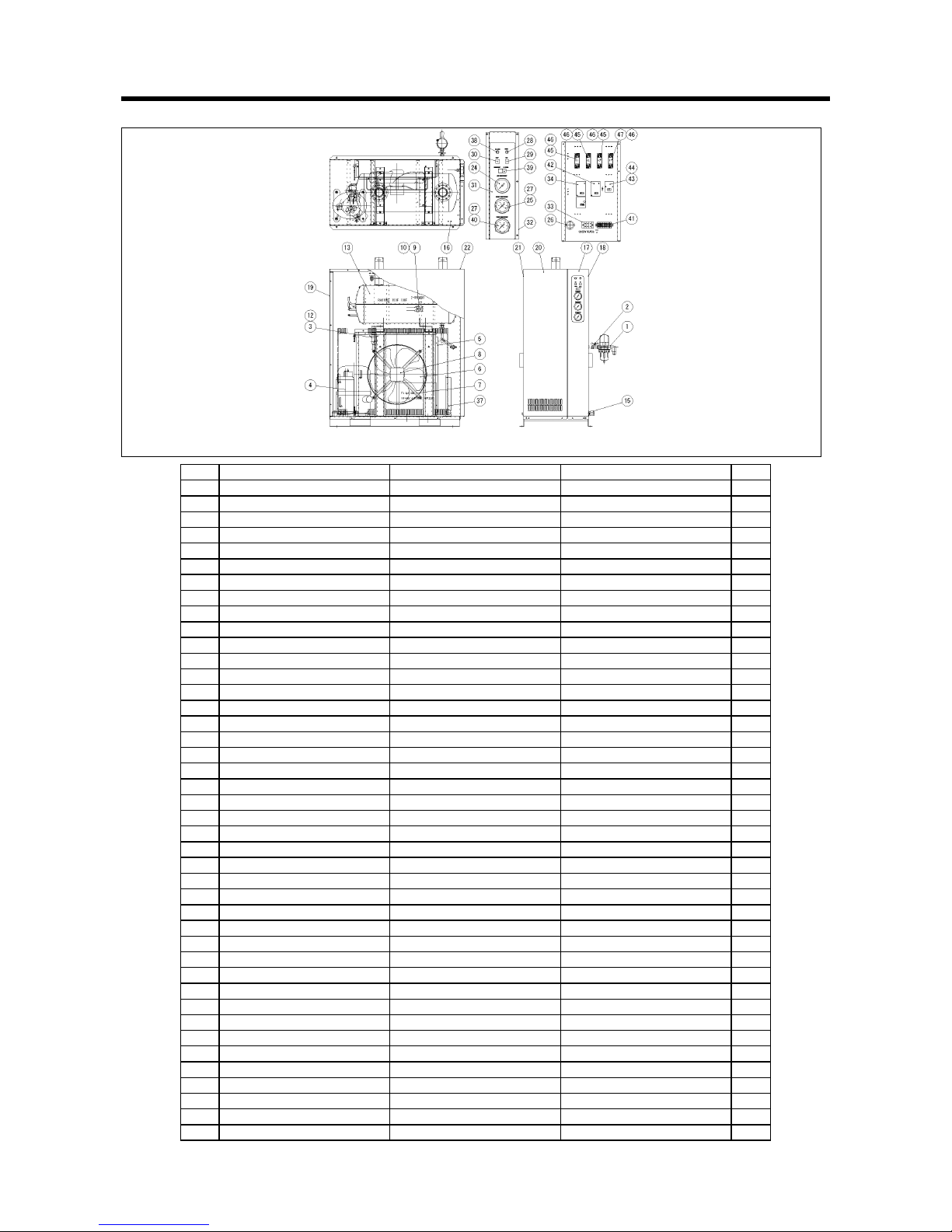
FR100A(50Hz) FR075AP
36
No. PART NAME 部品名稱 SPECIFICATION Q'TY
1 AUTO DRAIN TRAP ASSY. 自動排水器 AD-5 1
2 BALL VALVE 球閥 1/2" T201-04BTP 1
3 CAP ACITY CONTROL VALVE 熱旁通閥 WPR-1004DH-Q10 1
4 BARE COMPRESSOR 壓縮機本體 TFH-5524 (3φ 220V) 60Hz 1
5 CONDENSER 冷凝器 0A000491020(PC116) 1
6 FAN 風扇 400D (16") 1
7 FAN GUARD 風扇固定架 400D (16") 1
8 MOTOR 風扇馬達 YWF-4D-400D(16") 1
9 FAN CONTROL 風扇控制壓力開關 ACB-2114A 1
10 HIGH PRESSURE SWITCH 高壓壓力開關 ACB-2330 1
12 COPPER PIPE STRAINER 銅管過濾器 FS1033-35 (3/8”) 1
13 HEAT EXCHANGER SET 熱交換器 02090653020 RAX 120F 1
15 CABLE CONNECTOR 電纜固定頭
φ
20 1
16 BASE 底座 LGHC 1
17 RIGHT FRONT PANEL 右前板 EGC-B 1
18 RIGHT SIDE PANEL 右側板 EGC-B 1
19 REAR PANEL 後板 EGC-B 1
20 LEFT FRONT PANE L 左前板 EGC-B 1
21 LEFT SIDE PANEL 左側板 EGC-B 1
22 UPPER PANEL 上板 EGC-B 1
24 PRESSURE GAUGE 50 50 壓力錶 0-1.5MPa 1
25 PRESSURE GAUGE 50 50 壓力錶 6123-0914-00 1.5MPa 1
26 BUSH 線套
φ
30 3
27 FIXED METAL A 錶固定金具 LGHC 2
28 PILOT LAMP 指示燈 NB-281PGF AC220V 1
29 PUSH BUTTON SWITCH 按鍵開關 P13-1B (WHITE) 1
30 PUSH BUTTON SWITCH 按鍵開關 P13-1C (RED) 1
31 OPERATION PLATE FILM 操作面板貼紙 TETRONIC FILM 1
32 CONTROL PANEL 操作面板 LGC 1
33 TERMINAL BLOCK 端子台 TB112F 3P 25A 1
34 MAGNET SWITCH 電磁開關器 MSO-C12 220V NTH-11 1
37 SWITCH BOARD HOOD 配電盤 LGC 1
38 ALARM LAMP 故障指示燈(紅) NB-281 PRF AC220V(RED) 1
39 WAVY SWITCH 波形開關 SLE6D2 4A 250V 1
40 PRESSURE GAUGE 50 50 壓力錶 GK25-S27(6113-0010-00) 0-3MPa 1
41 TERMINAL BLOCK 卡式端子台 NHC-10-8P 1
42 MAGNETIC CONTACTOR 電磁接觸器 S-C12 AC220V 1a 1
43 Opposite phase relay 反向防止繼電器 APR-4 0
44 RELAY SOCKET 繼電器座 PF085A 1
45 RELAY 繼電器/補助繼電器 BMY-2C 5A 240V 0516B / K1 /1a1b 3
46 RELAY SOCKET 繼電器座 PYF-08A 3
47 RELAY 繼電器/時間繼電器 AMY-2 5A 250VAC / 2a 0
Page 39
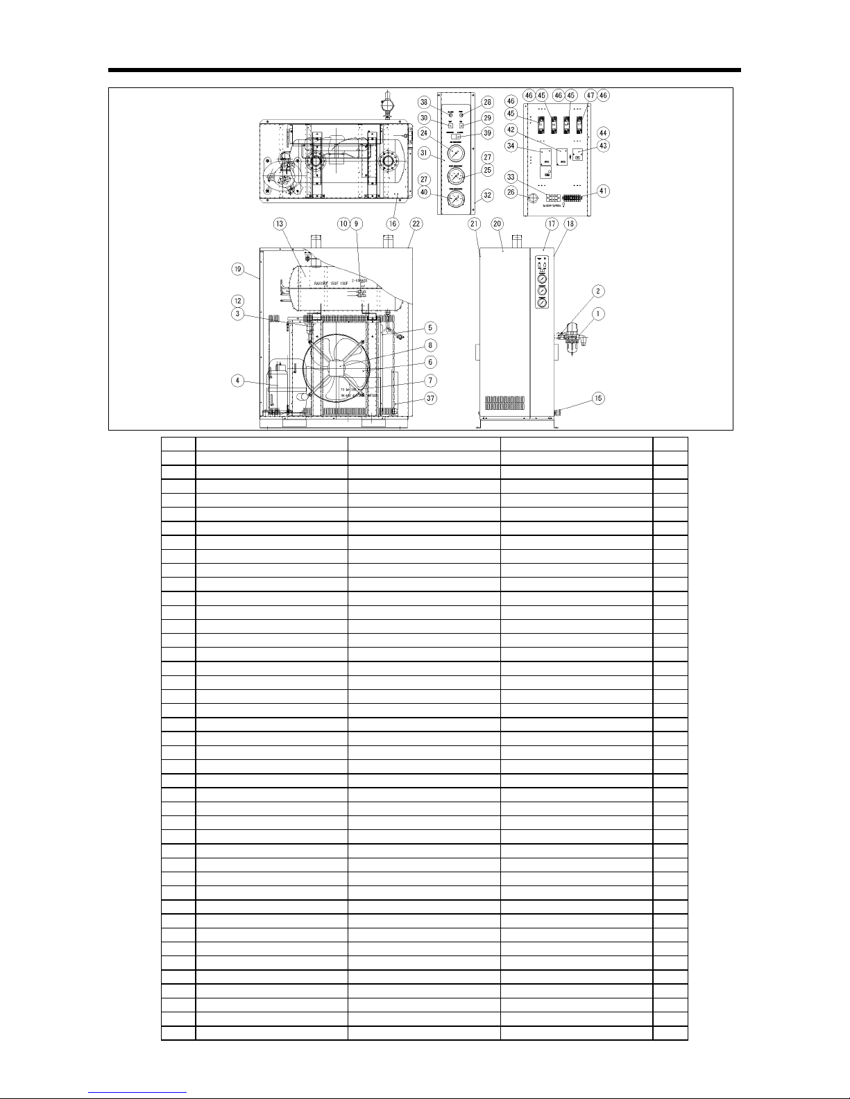
FR100A (60Hz)
37
No. PART NAME 部品名稱 SPECIFICATION Q'TY
1 AUTO DRAIN TRAP ASSY. 自動排水器 AD-5 1
2 BALL VALVE 球閥 1/2" T201-04BTP 1
3 CAP ACITY CONTROL VALVE 熱旁通閥 WPR-1004DH-Q10 1
4 BARE COMPRESSOR 壓縮機本體 KFPC262QZFC-F (3φ 220V) 1
5 CONDENSER 冷凝器 0A000491020(PC116) 1
6 FAN 風扇 400D (16") 1
7 FAN GUARD 風扇固定架 400D (16") 1
8 MOTOR 風扇馬達 YWF-4D-400D(16") 1
9 FAN CONTROL 風扇控制壓力開關 ACB-2114A 1
10 HIGH PRESSURE SWITCH 高壓壓力開關 ACB-2330 1
12 COPPER PIPE STRAINER 銅管過濾器 FS1033-35 (3/8”) 1
13 HEAT EXCHANGER SET 熱交換器 02090653020 RAX 120F 1
15 CABLE CONNECTOR 電纜固定頭
φ
20 1
16 BASE 底座 LGHC 1
17 RIGHT FRONT PANEL 右前板 EGC-B 1
18 RIGHT SIDE PANEL 右側板 EGC-B 1
19 REAR PANEL 後板 EGC-B 1
20 LEFT FRONT PANE L 左前板 EGC-B 1
21 LEFT SIDE PANEL 左側板 EGC-B 1
22 UPPER PANEL 上板 EGC-B 1
24 PRESSURE GAUGE 50 50 壓力錶 0-1.5MPa 1
25 PRESSURE GAUGE 50 50 壓力錶 6123-0914-00 1.5MPa 1
26 BUSH 線套
φ
30 3
27 FIXED METAL A 錶固定金具 LGHC 2
28 PILOT LAMP 指示燈 NB-281PGF AC220V 1
29 PUSH BUTTON SWITCH 按鍵開關 P13-1B (WHITE) 1
30 PUSH BUTTON SWITCH 按鍵開關 P13-1C (RED) 1
31 OPERATION PLATE FILM 操作面板貼紙 TETRONIC FILM 1
32 CONTROL PANEL 操作面板 LGC 1
33 TERMINAL BLOCK 端子台 TB112F 3P 25A 1
34 MAGNET SWITCH 電磁開關器 MSO-C12 220V NTH-11 1
37 SWITCH BOARD HOOD 配電盤 LGC 1
38 ALARM LAMP 故障指示燈(紅) NB-281 PRF AC220V(RED) 1
39 WAVY SWITCH 波形開關 SLE6D2 4A 250V 1
40 PRESSURE GAUGE 50 50 壓力錶 GK25-S27(6113-0010-00) 0-3MPa 1
41 TERMINAL BLOCK 卡式端子台 NHC-10-8P 1
42 MAGNETIC CONTACTOR 電磁接觸器 S-C12 AC220V 1a 1
43 Opposite phase relay 反向防止繼電器 APR-4 1
44 RELAY SOCKET 繼電器座 PF085A 1
45 RELAY 繼電器/補助繼電器 BMY-2C 5A 240V 0516B / K1 /1a1b 3
46 RELAY SOCKET 繼電器座 PYF-08A 3
47 RELAY 繼電器/時間繼電器 AMY-2 5A 250VAC / 2a 0
Page 40
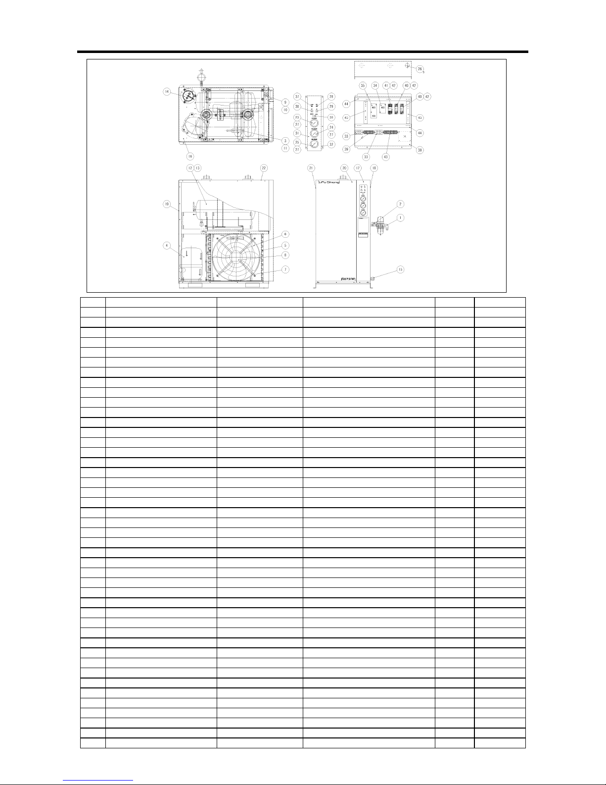
FR100AP FR150A FR075AP(50Hz)
38
No. PART NAME 部品名稱 SPECIFICATION Q'TY Q'TY(075AP)
1 AUTO DRAIN TRAP ASSY. 自動排水器 AD-5 1 1
2 BALL VALVE 球閥 111TP 1 1
3 CAPACITY CONTROL VALVE 熱旁通閥 CTX-12220DPQ105 1 1
4 BARE COMPRESSOR 壓縮機本體 3φ220V TFH5538C 1 1
5 CONDENSER 冷凝器 520×545-D 1 1
6 FAN 風扇 20” 1 1
7 FAN GUARD 風扇固定架 20” 1 1
8 MOTOR 風扇馬達 20” 1 1
9 FAN CONTROL 風扇控制壓力開關 ACB-2114A 1 1
10 HIGH PRESSURE SWITCH 高壓壓力開關 ACB-2330 1 1
11 COPPER PIPE STRAINER 銅管過濾器 DML083 1 1
12 HEAT EXCHANGER 熱交換器 TRX-150 1 0
13 HEAT EXCHANGER 熱交換器 TRX-100B 0 1
14 ACCUMULATOR SET 儲液筒 KF70WLE1D 1 1
15 BUSH 電纜固定頭 φ30 1 1
16 BASE 底座 LGHC 1 1
17 RIGHT FRONT PANEL 右前板 EGC-B 1 1
18 RIGHT SIDE PANEL 右側板 EGC-B 1 1
19 REAR PANEL 後板 EGC-B 1 1
20 LEFT FRONT PANEL 左前板 EGC-B 1 1
21 LEFT SIDE PANEL 左側板 EGC-B 1 1
22 UPPER PANEL 上板 EGC-B 1 1
23 PRESSURE GAUGE 50 50 壓力錶 GK25-S27(6113-0005-00)空氣用 1 1
24 PRESSURE GAUGE 50 50 壓力錶 6123-0914-00 1.5MPa 蒸發壓力用 1 1
25 PRESSURE GAUGE 50 50 壓力錶 GK25-S27(6113-0010-00) 0-3MPa 凝縮器用 1 1
26 BUSH 線套 φ30 3 3
27 FIXED METAL A 錶固定金具 LGHC 3 3
28 PILOT LAMP 指示燈 AC220V(綠) 1 1
29 PUSH BUTTON SWITCH 按鍵開關 (WHITE) 1 1
30 PUSH BUTTON SWITCH 按鍵開關 (RED) 1 1
31 OPERATION PLATE FILM 操作面板貼紙 TETRONIC FILM 1 1
32 CONTROL PANEL 操作面板 EGC-B 1 1
33 TERMINAL BLOCK 端子台 TB-30 (3P) 2 2
34 MAGNETIC CONTACTOR 電磁接觸器 C-12D 1NO1NC 220V 1 1
35 MAGNET SWITCH 電電磁開關 C-18D 1NO1NC 220V GTH-11/3 11A 1 1
37 ALARM LAMP 故障指示燈 AC220V(赤) 1 1
38 SWITCH BOARD BASE 配電盤底座 EGC-B 1 1
39 TERMINAL BLOCK 卡式端子台 NHC-10-8P 1 1
40 RELAY 繼電器/補助繼電器 MY2 AC220V/240V 2 2
41 TIME RELAY 時間繼電器 H3Y-2 220V 5SEC 1 1
42 RELAY SOCKET 繼電器座 PYF08A 3 3
43 TERMINAL BLOCK 卡式端子台 NHC-10-11P 1 1
44 ELECTRIC WIRE DUCT 配線槽 HD-1-L607 2 2
45 ELECTRIC WIRE DUCT 配線槽 HD-1-L247.5 2 2
Page 41

Page 42

Page 43

Page 44
Fu Sheng Industrial Co., Ltd. Machinery Division
N
o. 60 Kwang Fu Road, Sec. 2 San Chung City 241, Taipei County, Taiwan
Tel : 886-2-2995-1411 Fax : 886-2-2995-7925
Headquarter
N
o. 172 Nanking East Road, Sec. 2,Taipei, Taiwan, R.O.C
 Loading...