

Furuno USA 9ZWWR2100 User Manual
9. PC operation
9.1. File
1) File Play: To play a regular echo recorded file (idx)
(Refer “2) Acquisition” on 9.3.1.)
2) Snapshot: To indicate captured radar screen (jpg).
3) Exit: To exit the software of RainMap.
4) Operation mode: (Click “File” + [Ctrl] + [Alt] at
same time to Indicate the menu)
Do this operation mode after changed some
parameters to operate a radar.
- Observation:
Select the entered values at “Setting” menu
with regular mode.
- Verify operation during installation:
Change some parameters automatically to
verify operation during installation.
All parameters will set back to previous
setting (before this verify operation) if go
back to “Observation”
SSE-14-0023_2
9.2. Disp
1) DispSelect
- 2D: Indicate the echo by 2 dimension.
- 3D: Indicate the echo by 3 dimension.
2) Sub echo:
3) Information Indication: *Under construction.
To show another screen to indicate
the echo
9.3. Setting
9.3.1. Setting
1) View
Range [km]
To setup an indication range.
♦ Confirm and setup the value before s hipping.
DataType
To select an indication of the radar parameter.
・ Rainfall intensity: Intensity of rainfall [mm/h]
・ Reflective intensity (H): Reflection factor of
the horizontal polarimetric radar [dBz]
・ Reflective intensity (V): Reflection factor of the vert ical polarimetric radar [dBz]
・ Doppler speed: Doppler speed [m/s]
・ Zdr [dB]: Radar reflection factor difference.
・ Kdp [deg/km]: Propagation phase difference rate of change.
9-1

SSE-14-0023_2
Multiple parameter output
setup only when Echo data
an output record of
Scanning line
Ratio of transparency [%]
To setup a Transmittance of the indication
echo.
2) Acquisition
Notice: Turn “OFF” all the setting before shipping.
Rec echo
Turn ON or OFF a Log of echo data.
Rec file type
To select a log form of echo data.
(dat (idx) / ZIP / dat (idx) + ZIP)
Echo folder
To setup a log folder of echo data.
Echo zip folder
To setup a log folder of echo zip dat a file.
Rec interval [sec]
To setup a recording interval of echo data.
Rec time [hour]
To setup a time of recording echo data.
Screen capture
Turn ON or OFF a screen capture.
Capture folder
To setup a folder of capture (jpg).
Rec interval [sec]
To setup an interval time of capt ure.
Rec CSV
Turn ON or OFF a recording of CSV data.
Echo folder (CSV)
To setup a folder of CSV data.
CSV Rec interval [sec]
To setup an interval time of CSV data.
CSV Rec parameter
To select a weather parameter of recording
CSV.
- Rain [mm/h]: Intensity of rainfall
- Zhh [dBz]: Reflection factor of the
horizontal polarimetric radar
- Zvv [dBz]: Reflection factor of the
vertical polarimetric radar
- DS [m/s]: Doppler speed
- Zdr [dB]: Radar reflection factor
difference
- Kdp [deg/km]: Propagation phase
difference rate of change.
Turn ON or OFF a scan line of screen.
Turn ON or OFF an output record of
multi-parameter.
(*It could setup only when Echo data
mode of TRX is applied)
Multiple parameter output folder
To setup a folder of recording
multi-parameter (scn).
(*It could
mode of TRX is selected)
Rainfall information output
(*It will indicate during factory setting)
Turn ON or OFF
rainfall information.
Rainfall information output folder
(*It will indicate during factory setting)
To setup a folder of recording rainfall
information.
9-2
3) Antenna
Notice: Follow a value of the management list to setup.
Latitude [deg]
To setup a latitude of the instal l ed point.
Longitude [deg]
To setup a longitude of the installed point.
Altitude [m]
To setup an altitude of the instal l ed point.
Image
To setup a filename of map.
This program treats as the equidistant cyli ndri cal
projection.
Left Top Latitude [deg]
To setup a latitude of left top corner of Map Image.
Left Top Longitude [deg]
To setup a longitude of left top corner of Map Image.
Right Bottom Latitude [deg]
To setup a latitude of bottom right corner of “Map Image”.
Right Bottom Longitude [deg]
To setup a longitude of bottom ri ght corner of “Map Image”.
4) Scan
There are 5 scan patterns that could customize
and save a setting.
Notice: Follow a value of the management list to
setup on scan pattern 1.
ScanMode
To select a scan mode of antenna.
・ PPI scan: Equiangular elevation with horizontal
rotation mode. It generates 2 dimension data.
・ Spiral scan: The mode to rotate horizontal
while shifting elevation continuously, and scans
in a spiral. It generates 3 dimension data.
・ Sector RHI scan: The mode to scan elevation direction on special direction area, and
generate 3 dimension of rectangular solid angle.
・ HSQ scan: The mode to activate PPI scan while shifting an elevation. It generates 3
dimension data.
HSQ Period [min]
To select an periodic movement of HSQ during HSQ mode.
(1(60/(H)) / 2(30/(H)) / 3(20/(H)) / 4(15/(H)) / 5(12/(H)) / 6(10/(H)) / 10(6/(H)) / 12(5/(H)))
e.g. HSQ will activate every 2 minutes if select 2/ 30/(H). (It turns 30 times per hour)
PPI elevation [deg]
To setup an angle of antenna’s elevation durin g PPI mode.
PPI azimuth rotation speed [rpm]
To setup a rotation speed of azimuth in
rotation per minutes (rpm).
Parameters affect only to PPI mode.
SSE-14-0023_2
9-3

SSE-14-0023_2
SPI operation mode
To setup an elevation angle st ep and azimuth rotation speed.
For example, when the setting is shown as below table 1, antenna wi ll rotat e at 2.99, 3.99 an d
6.99 degrees.
table 1 (Example of SPI (Spiral) operation )
SPI operation mode 2 [deg], 10 [rpm]
SPI lower elevation angle 2.99 [deg]
SPI horizontal scan rotation 3
SPI lower elevation angle [deg]
To setup an angle of SPI lowest elevation.
SPI mode will start from setup angle to upper angle.
SPI horizontal scan rotation number
To setup a number of rotation in horizontal direction of SPI scan.
It will move upward/downward as setup number wh i le rotating on azimuth direction.
SRHI elevation speed [rpm]
To setup an elevation speed of SRHI (S ector RHI).
SRHI azimuth 0 [deg]
To setup an angle of azimuth.
It will observe RHI in between azimuth 0 to 1 continuously.
SRHI azimuth 1 [deg]
To setup an angle of azimuth during SRHI observation.
SRHI azimuth step [deg]
To setup a quantity of antenna rotat ion while changing an angle of azimuth.
SRHI elevation 0 [deg]
To setup an angle of elevation.
SRHI will start from elevation 1 to 2.
SRHI elevation 1 [deg]
To setup an angle of elevation in HSQ (Hori zontal Sequence) observation.
HSQ elevation movement azimuth rotation speed [rpm ]
To setup an azimuth rotation speed until the elevation movement in HSQ (Horizontal
Sequence) observation.
HSQ elevation movement difference rotation speed [rp m]
To setup a rotation speed of elevation direction during elevation chang e in HSQ (Horizontal
Sequence) observation.
Rotation speed of elevation direction = [HSQ elevation m oving direction of rotation speed] +
[HSQ elevation movement difference of rotation speed]
Notice: [HSQ elevation moving direction of rotation speed] ≧ [HSQ elevation movement
difference of rotation speed]
HSQ measurement azimuth rotation speed [rpm]
To setup an azimuth rotation speed at fixed elevation angle.
HSQ status delay azimuth revolution [deg]
To setup an angle of shifting elevation in HSQ (Horizontal Sequence) observat ion.
HSQ setting elevation 0 – 31 [deg]
To setup an elevation variation.
It is possible to setup 32 elevation.
Parameter Settings
9-4
9.3.2. Service
Press [Ctrl] + [Alt] and click [Setting] simultaneously to indicate service menu.
Service menu has two types:
1. Maintenance setting: Regular menu for maintenance service engineer.
2. Factory setting: Adjust the setting of installed station use only for installation engineer.
Notice: Follow the management list to setup all values.
1) Network
Command transfer IP
To setup the IP address of command transfer.
♦ Constant value: 192.168. 1.101
Command transfer port
To setup the port number of comm and transfer.
♦ Constant value: 51000
Data transfer IP
To setup the IP address of data transfer.
♦ Constant value: 192.168. 1.101
Data transfer port
To setup the port number of data transfer.
♦ Constant value: 52000
FTP server address
To setup the IP address of FTP server.
♦ Constant value: 192.168. 1.100
FTP server port
To setup the port number of FTP server.
♦ Constant value: 50000
2) TRX
Echo data mode
To select Echo data mode.
- IQ Data: Use amplitude of Horizontal wave only.
- Multiple Parameter: Use all information of
reflected wave such as H/V amplitude and
phase.
Rainfall intensity calculation method
To select a calculation method of Rai nfall intensity
calculation.
・ Zh method: Use horizontal amplitude
information only.
・ Zh,Kr Attenuation correction method: Zh is calculated from the value that corrected rain
attenuation by the amplitude.
・ Zh,
・ Zh, Zdr method: Calculated from Zh and Zdr.
・ Zdr, Kdp+Zh method: Add into Zh after calculated from Kdp and Zdr.
・ Kdp+Zh: Use complex information, amplitude, and phase.
Sweep decimation
To setup a number of decimation.
Size of transfer data. It uses the setting table when to determine a factor.
Pulse spec.
To setup a pulse number.
Refer to the setting table as details of pulse setti ngs.
SSE-14-0023_2
φ dp method: Zh is calculated from the value that corrected rain attenuation by the φ dp.
9-5
Chirp polarity
(*It will indicate during factory setting)
To select frequency shift direct ion.
Up Charp: Sweep frequency to upward.
Down Charp: Sweep frequency to downward.
IF frequency [MHz]
(*It will indicate during factory setting)
To setup an IF (Intermediate Freque ncy) signal frequency.
DAC output Level [dB]
(*It will indicate during factory setting)
To setup an amplitude of transmi ssion signal output from SPU.
3) RDR Parameter
RF frequency [MHz]
(*It will indicate during factory setting)
To setup a carrier frequency of transmitting signal.
Light speed [m/s]
(*It will indicate during factory setting)
To setup a propagation speed of radio wave.
Antenna rotation speed (H) [rpm]
To setup a horizontal rotati on speed of antenna.
Beam width (H) [deg]
(*It will indicate during factory setting)
To setup an angle (Beam width) that -3dB beam width of antenna in horizontal polarization.
Beam width (V) [deg]
(*It will indicate during factory setting)
To setup an angle (Beam width) that -3dB beam width of antenna in vertical polarizat i on
Azimuth offset
(*It will indicate during factory setting)
To setup an azimuth offset angle from origin to north.
4) Interference Rejection
Interference rejection 0 - 1
Turn On or OFF an interference rejection function
from other radar.
Power adjustment
(*It will indicate during factory setting)
To select High or Low to adjust the power of IR0 -1.
Threshold
(*It will indicate during factory setting)
To setup a threshold of judging interference wave.
Interpolation
(*It will indicate during factory setting)
Turn On or OFF an interpolation.
SSE-14-0023_2
It indicates only when Factory setting is on
It indicates only when Factory setting is on
9-6
5) Matched Filter
Matched Filter
Turn “ON” when to use QON and VON.
This is a setting of receiving digital filter.
6) Sector Blank
Sector Blank 1 -2
Turn ON or OFF a setting of transmission prohibited
area. (Setup a rectangular solid angle area of
Azimuth and Elevation)
Azimuth Start angle [deg]
To setup a starting angle point of azimuth direction.
Starting point of azimuth is 0 degree on this unit.
Follow a clockwise direction.
Azimuth End angle [deg]
To setup an ending angle point of azimuth direction.
Elevation Start angle [deg]
To setup a starting elevation angle. Horizontal
direction is 0 degree. Follow a zenithal direction.
Elevation End angle [deg]
To setup an ending angle point of el evat ion.
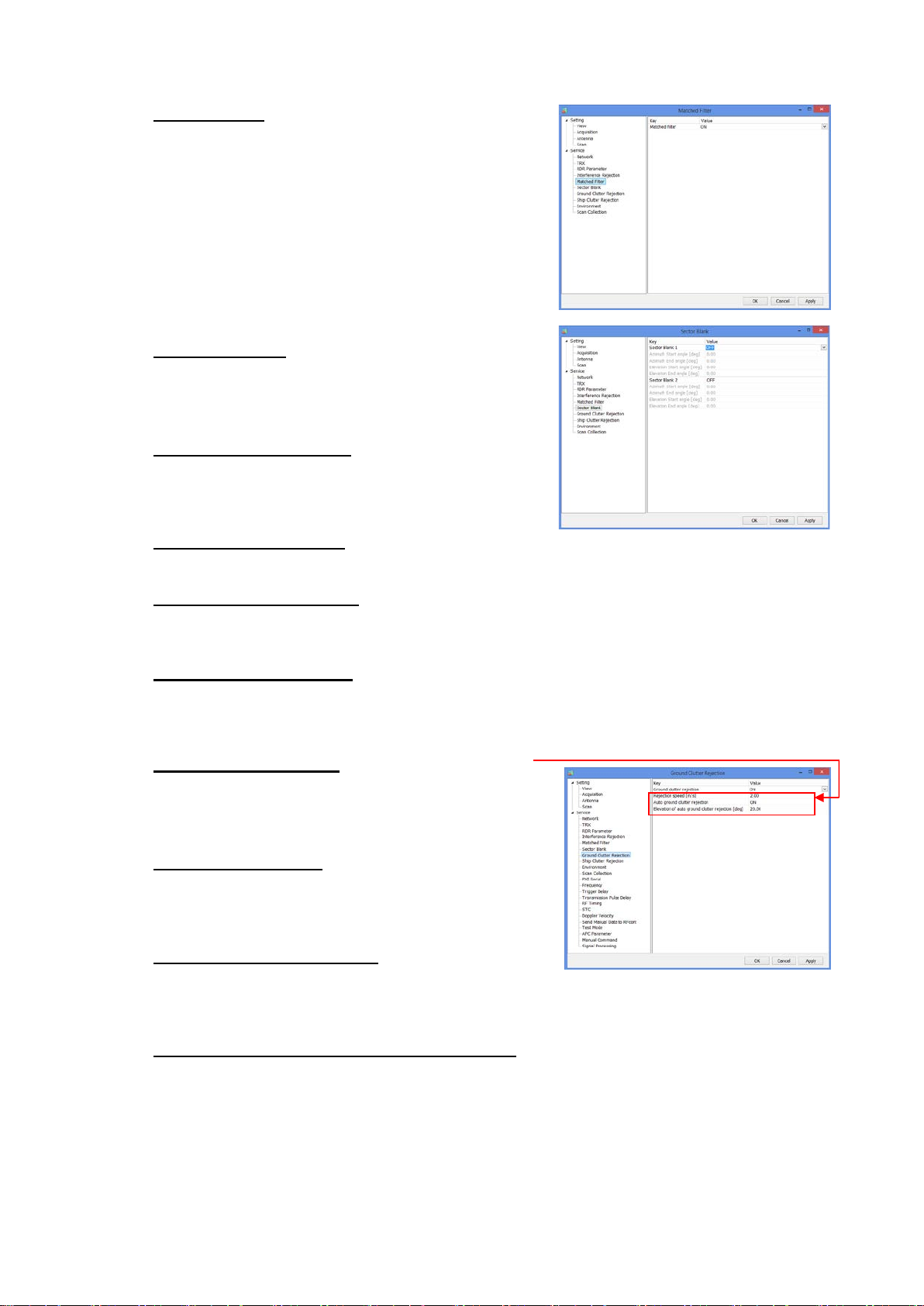
7) Ground Clutter Rejection
Ground clutter rejection
Turn ON or OFF a judgment to remove ground
clutter as a target if moving speed is lower than
setting speed.
Rejection speed [m/s]
(*It will indicate during factory setting)
To setup a removal speed (upper limit) of judging
ground clutter.
Auto ground clutter rejection
(*It will indicate during factory setting)
Turn ON or OFF an auto ground clutter rejection. Turn it “OFF” if elevation is above setting
value.
Elevation of auto ground clutter rejection [deg]
(*It will indicate during factory setting)
To setup an angle of boundary elevati on to turn off ground clutter rejection.
SSE-14-0023_2
It indicates only when Factory setting is on
9-7
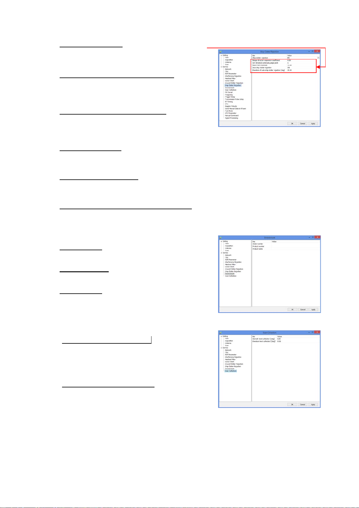
8) Ship Clutter Rejection
Ship clutter rejection
Turn ON or OFF for determine whether a target is
a ship and to eliminate.
Range direction expansion coefficient
(*It will indicate during factory setting)
To setup a range to expand a ship and t he data to
judge in the range direction.
SW direction continuity judge point
(*It will indicate during factory setting)
To setup a point to judge the continuity of the sweep
direction
RainCFAR threshold
(*It will indicate during factory setting)
To setup a threshold to judge as a shi p.
Auto ship clutter rejection
(*It will indicate during factory setting)
To setup a threshold to judge as a shi p.
Elevation of auto ship clutter rejection [deg]
(*It will indicate during factory setting)
To setup an angle of boundary elevati on to turn off ship clutter rejection.
It indicates only when Factory setting is on
9) Environment
Serial number
Enter the serial number.
Product number
Enter the product number.
Product name
Enter the product name.
SSE-14-0023_2
10) Scan Collection
Azimuth level collection [deg]
To setup an azimuth offset from initial posit i on.
Parameters affect to elevation angle calibration.
It adjusts the offset of magnet sensor by elevation
calibration.
Elevation level collection [deg]
To setup an elevation offset from horizontal level.
Measure the elevation angle after antenna
initialization and set a field.
9-8

9.3.3. Factory setting
ANT control port
1. Click “Setting” + [Ctrl] + [Alt] simultaneously to Indicate the equipment setting of Service
menu.
2. [Factory setting] button will indicate on the right side menu when clicked [Service] in the left
menu.
3. Pop-up menu of [Enter password of Factory setting] will indicate when clicked [Factory
setting] button.
Enter Password:
rainmap
SSE-14-0023_2
4. Factory setting menu will indicate below Service menu after entered the password
1) PXI Serial
RF control port
To Open or Close RF control port.
Port number
To setup a port number.
Baud rate [bps]
To setup a baud rate.
Data bit [bit]
To setup a data bit.
Stop bit [bit]
To setup a stop bit.
Parity
To select the setting.
(none / odd / even / mark / space)
To Open or Close ANT control port.
ANT monitor port
To Open or Close ANT monitor port.
9-9
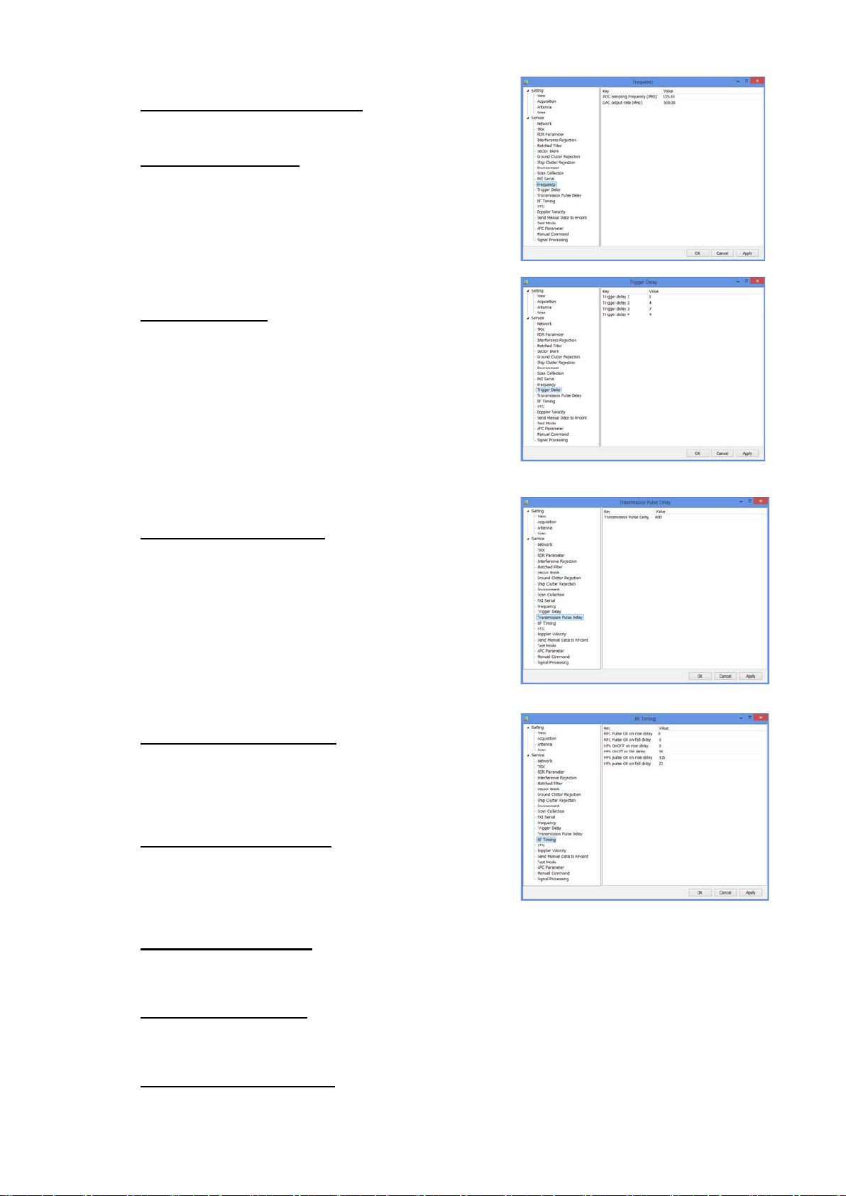
2) Frequency
ADC sampling frequency [MHz]
To setup a sampling frequency of AD converter.
DAC output rate [MHz]
To setup an output rate of DA converter.
3) Trigger delay
Trigger delay 1 - 4
To setup a trigger delay timing #1 - #4 of
transmission signal.
4) Transmission Pulse Delay
SSE-14-0023_2
5) RF Timing
Transmission Pulse Delay
To setup a clock frequency (normally 125MHz) of
transmission pulse delay.
RFC pulse ON on rise delay
To setup a clock frequency (normally 125MHz) of
RFC pulse on rise delay.
It turns “OFF” a pulse of LNA bias during a period of
transmission. RF_trig rise against delay ti me.
RFC pulse ON on fall delay
To setup a clock frequency (normally 125MHz) of
RFC pulse on fall delay.
It turns “OFF” a pulse of LNA bias during a period of
transmission. RF_trig fall against delay time.
HPA OnOff on rise delay
Control signal (the power is “OFF” during HPA receiving period) of HPA power switch (drain
voltage) could setup a rise delay time for RF_Trig.
HPA OnOff on fall delay
Control signal (the power is “OFF” during HPA receiving period) of HPA power switch (drain
voltage) could setup a fall delay time for RF_Trig.
HPA pulse ON on rise delay
Control signal (the power is “OFF” during HPA receiving period) of HPA power switch (pulse
voltage) could setup a rise delay time for RF_Trig.
9-10
 Loading...