

Furuno USA 9ZWRTR124 User Manual
3.7 Lost Target
[AIS TARGET MENU]
1 BACK
2 SLEEP ALL TARGETS
NO/YES
3 ACTIVATE ALL TARGETS
NO/YES
4 ACK LOST TARGETS
NO/YES
5 [AIS DISP FILTER]
6 [CPA AUTO ACTIVATE]
7 [AIS LOST FILTER]
[AIS LOST FILTER]
1 BACK
2 AIS LOST FILTER
OFF/FILT/ALL
3 MAX RANGE
OFF/ON
4 MAX RANGE VALUE
03.0km
5 MIN SHIP SPEED
OFF/ON
6 MIN SHIP SPEED VALUE
00.0km/h
7 EXCEPT CLASS B
OFF/ON
8 MIN SHIP LENGTH
OFF/ON
9 MIN SHIP LENGTH VALUE
000m
Click
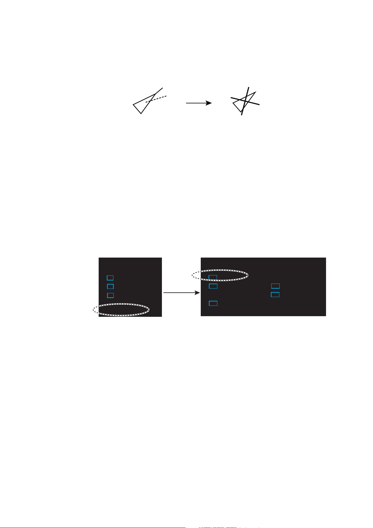
When AIS data is not received from a target within 3-5 report intervals (see Note 2),
the target symbol changes to the lost target symbol (flashing). No audio or visual alarm
is given for a lost target.
Activated target Lost target
Note: The AIS data transmission interval depends on target’s speed. For example, the
data is transmitted every 10 seconds on ship speed of 0 to 14 knots and every two
seconds on the ship speed of more than 23 knots. For details see the operator’s
manual of the AIS transponder.
3.7.1 Lost target filter
If there are a lot of AIS targets in your area, the lost target alarm may sound frequently.
In this case you may wish to have the alarm ignore lost targets whose range, speed,
class or length are below the threshold value you specify.
3. AIS OPERATION
1. Right-click the [AIS] icon to show [AIS TARGET MENU].
2. Click [AIS LOST FILTER].
3. Click [AIS LOST FILTER] in the [AIS LOST FILTER] menu.
4. Click the target alarm to enable.
[OFF]: Disable the alarm.
[FILT]: Get the alarm against the targets whose criteria meet the settings on the
[AIS LOST FILTER] menu.
[ALL]: Get the alarm against all lost targets.
5. Click [MAX RANGE VALUE] and [MIN SHIP SPEED VALUE] as appropriate, referring to the description below.
[MAX RANGE], [MAX RANGE VALUE]: Any AIS lost target beyond the range set
here is not shown.
[MIN SHIP SPEED], [MIN SHIP SPEED VALUE]: Any AIS lost target slower than
this setting is not shown.
[EXCEPT CLASS B]: Select [ON] to prevent trigger lost Class B AIS lost target.
[MIN SHIP LENGTH], [MIN SHIP LENGTH VALUE]: Any AIS lost target whose
length is shorter than this setting is not shown.
3.7.2 How to acknowledge a lost target
1. Click the [AIS] icon to show [AIS TARGET MENU].
2. Right-click [ACK LOST TARGETS].
3-7
3. AIS OPERATION
[AIS]
1 BACK
2 SYMBOL COLOR
GRN/BLU/CYA/MAG/WHT
3 ROT TAG LIMIT
000.0deg/min
4 SCALED SYMBOL
OFF/ON
3. Click [YES]. The lost target disappears from the screen.
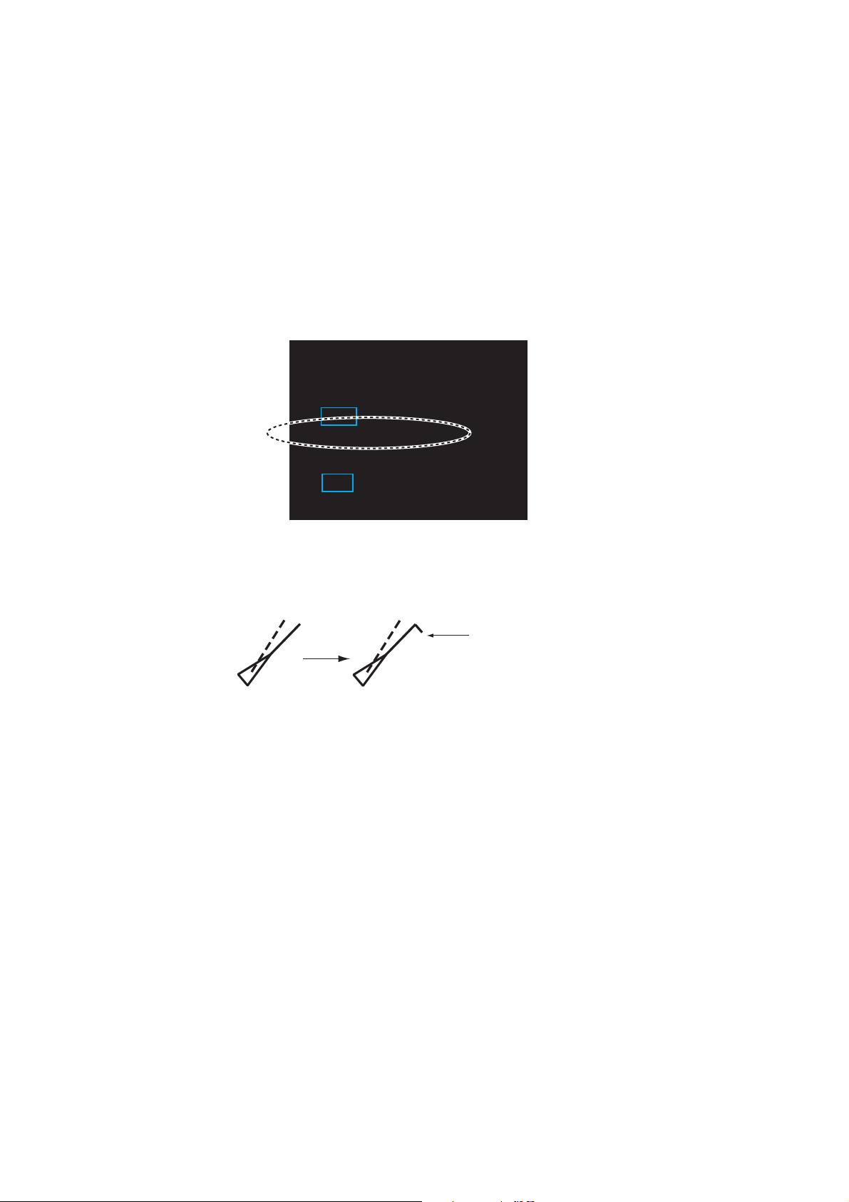
3.8 ROT Setting
You may set the lower limit of the ROT (Rate Of Turn) at which the heading line on
target symbols points the ship’s turning direction.
1. Open [MAIN MENU], click [TT
2. Click [SYMBOL].
3. Click [AIS].
4. Click [ROT TAG LIMIT].
5. Click the setting value then enter ROT with the setting knob (setting range: 0.1 to
720.0 (deg/min)).
6. Click outside the menu window to close the menu.
.
AIS].
Ship turning to
starboard
3.9 CPA/TCPA Alarm
The AIS continuously monitors the predicted range at the Closest Point of Approach
(CPA) and predicted time to CPA (TCPA) of each AIS target. When the predicted CPA
of an AIS target becomes smaller than a preset CPA range and its predicted TCPA
less than a preset TCPA limit, the audio alarm sounds. In addition, the symbol of the
offending AIS target is red and flashes together with its vector.
CPA/TCPA alarm ranges must be set up properly taking into consideration the size,
tonnage, speed, turning performance and other characteristics of own ship.
The reference point for CPA, TCPA calculation may be selected from antenna position
or conning position.
To set this alarm, see section 2.12 "CPA/TCPA Alarm".
3-8
3.10 Automatic Target Activation
[CPA AUTO ACTIVATE]
1 BACK
2 CPA AUTO ACTIVATE
OFF/FILT/ALL
3 MAX RANGE
OFF/ON
4 MAX RANGE VALUE
03.0km
5 MIN SHIP SPEED
OFF/ON
6 MIN SHIP SPEED VALUE
00.0km/h
7 EXCEPT CLASS B
OFF/ON
8 MIN SHIP LENGTH
OFF/ON
9 MIN SHIP LENGTH VALUE
000m
You can get automatic activation of a sleeping AIS target when its CPA is within the
CPA/TCPA alarm setting. Further, you can select which AIS targets to automatically
activate.
1. Right-click the [AIS] icon to show the [AIS TARGET MENU] window.
2. Click [CPA AUTO ACTIVATE].
[AIS TARGET MENU]
1 BACK
2 SLEEP ALL TARGETS
NO/YES
3 ACTIVATE ALL TARGETS
NO/YES
4 ACTIVATE ALL TARGETS
NO/YES
5 [AIS DISP FILTER]
6 [CPA AUTO ACTIVATE]
7 [AIS LOST FILTER]
3. Click [CPA AUTO ACTIVATE].
3. AIS OPERATION
4. Click the activating mode for AIS target.
[OFF]: Disable automatic activation of AIS target by CPA.
[FILT]: Activate only the targets that fulfill the requirements set on the [CPA AUTO
ACTIVATE] menu.
[ALL]: For all targets.
5. Set items 3 to 9 referring to the description below.
[MAX RANGE], [MAX RANGE VALUE]: Any AIS target beyond the range set here
will not be activated.
[MIN SHIP SPEED], [MIN SHIP SPEED VALUE]: Any AIS target slower than this
setting will not be activated.
[EXCEPT CLASS B]: Select [ON] to prevent automatic activation of class B AIS
targets.
[MIN SHIP LENGTH], [MIN SHIP LENGTH VALUE]: Any AIS target whose length
is shorter than this setting will not be activated.
6. Click outside the menu window to close the menu.
3-9

3. AIS OPERATION
AIS
Selected AIS to
display the information
3.11 AIS Target Data
You may display an AIS target’s data by selecting it on the display. This data is shown
for the activated AIS target only. The selected AIS target is enclosed in a broken
square. The target data is shown on the [AIS INFO] window.
[AIS INFO]
NAME :XXXX
FLAG :NETHERLANDS
CALL SIGN :PFXXXX
MMSI :123456789
IMO NO. :missing
LAT :51°53.661’ N
LON :004°18.376’ E
km
RNG/BRG :0.77
SOG/COG :11.1
CPA/TCPA :0.49km/03m10s
HDG :missing
ROT :missing
LEN/BEAM :135m/14.0m
BLUE SIGN :NO
/324.4°R
km/h
/100.0°T
[AIS INFO] window
[NAME]: Name of ship [RNG/BRG]: Range/Bearing to target
[FLAG]: Flag state [SOG/COG] (or [STW/CTW]): Target’s
[CALL SIGN]: Call sign
speed and course
[MMSI]: MMSI No. [CPA/TCPA]: Target’s CPA/TCPA
[IMO NO.]: IMO No. [HDG]: Heading
[LAT]: Latitude [ROT]: Rate of turn
[LON]: Longitude [LEN/BEAM]: Ship’s length/Beam
[BLUE SIGN]: Blue sign status
Symbol operation
Left-click the AIS target to show the selected target's information window.
Menu operation
1. Right-click the AIS target to show the [AIS] window.
[AIS]
1 BACK
2 TARGET DATA
3 ACTIVE/SLEEP
2. Click [TARGET DATA] to show the [AIS INFO] window.
3. Click the close button or outside the information window to close the menu.
3-10
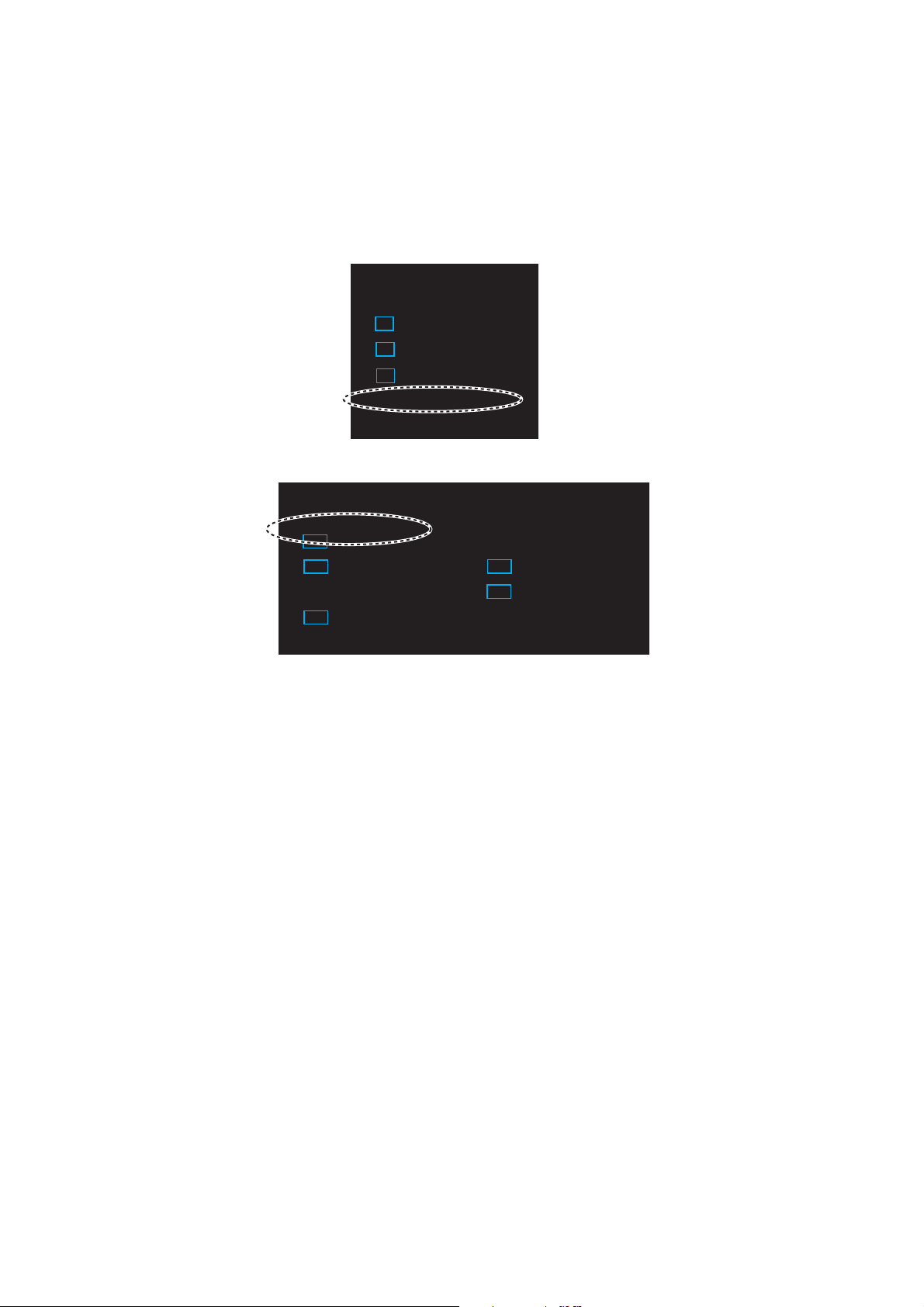
3.12 AIS List
[LIST] icon for AIS
N
N
01m0
REL
E
[LIST] icon for AIS
N
N
01m0
REL
E
The AIS list provides a comprehensive information about all AIS targets being tracked.
How to display the AIS list
Click the [LIST] icon for AIS at the bottom right corner on the screen.
3. AIS OPERATION
[LIST] icon for AIS
LIST
VRM1
VRM2
AIS
FLT
►
1.567
0.160
►
ON
AUTO
NM
NM
13m
TUN
MA
MA
Click
[AIS LIST] <SORT>NAME-UP 1/1
MMSI NAME
12XXXXXXXXX ABCXX
2345XXXXXXX AXX
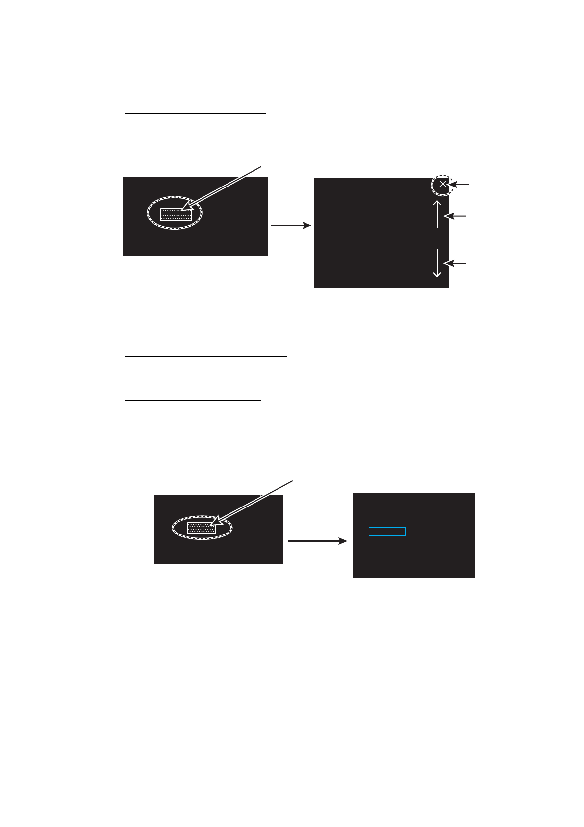
AIS list
Close
button
Page up
button
Page down
button
You can see [MMSI] and [NAME] for AIS targets. To close the [AIS LIST] window, click
the close button on the list.
How to display AIS target data
Click the target on [AIS LIST] to show the [AIS INFO] window. See section 3.11.
How to sort the target list
You may sort the target list by RANGE, CPA, TCPA. Also, you can sort in ascending
or descending order.
1. Right-click the [LIST] icon for AIS to show the [AIS-LIST] window.
[LIST] icon for AIS
13m
ON
AIS
AUTO
NM
NM
TUN
MA
MA
Right-click
LIST
VRM1
VRM2
FLT
►
1.567
0.160
►
2. Click [SORT BY].
3. Click the sorting method desired.
[NAME-UP], [NAME-DOWN]: Sort by name
[RANEG-UP], [RANGE-DOWN]: Sort by range
[CPA-UP], [CPA-DOWN]: Sort by CPA
[TCPA-UP], [TCPA-DOWN]: Sort by TCPA
4. Click outside the menu window to close the menu.
[AIS-LIST]
1 BACK
2 SORT BY
NAME-UP /NAME-DOWN/
RANGE-UP/RANGE-DOWN/
CPA-UP/CPA-DOWN/
TCPA-UP/TCPA-DOWN
3-11

3. AIS OPERATION
This page is intentionally left blank.
3-12
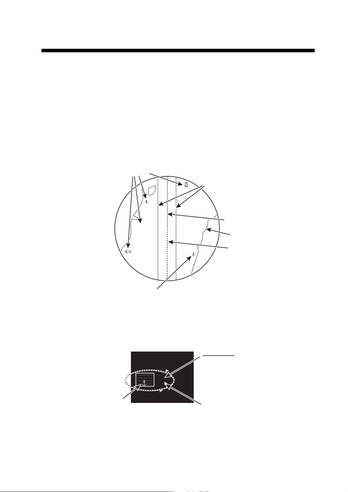
4. RADAR MAP
Navlines
(by NAV LINE icon)
Heading line
Stern mark
Approximate
coast line
X
Mark symbols
Mark symbols
F
MARK
Mark shape
Color of the mark
Display icon
[ON]: Shows all the marks
currently selected at the
[MARK] icon.
[OFF]: Hides all marks currently
selected at the [MARK]
icon.
[MARK] icon
4.1 What is a Radar Map?
The radar map feature, available in the [RIVER] mode, is a combination of map lines
and symbols whereby the user can define and input the navigation, route planning and
monitoring data on the screen. Map lines are a navigational facility whereby the observer can define lines to indicate channels or traffic separation schemes.
The user can create a radar map on real-time base while using the radar for navigation
or at leisure time at anchor. The map data is stored on the Flash ROM memory which
is mounted on the main processor board.
Note: Radar map function requires heading and positioning data.
4.2 [MARK] icon
The [MARK] icon, located at the bottom left corner on the screen, is used to create
marks and lines, line operations. This radar can save a total of 5,000 marks and lines.
MENU
BARGE
ON
2WHT
MARK
ON
DOCK OF
CYA
BRL2-3
ECHO
GRN
4-1
4. RADAR MAP
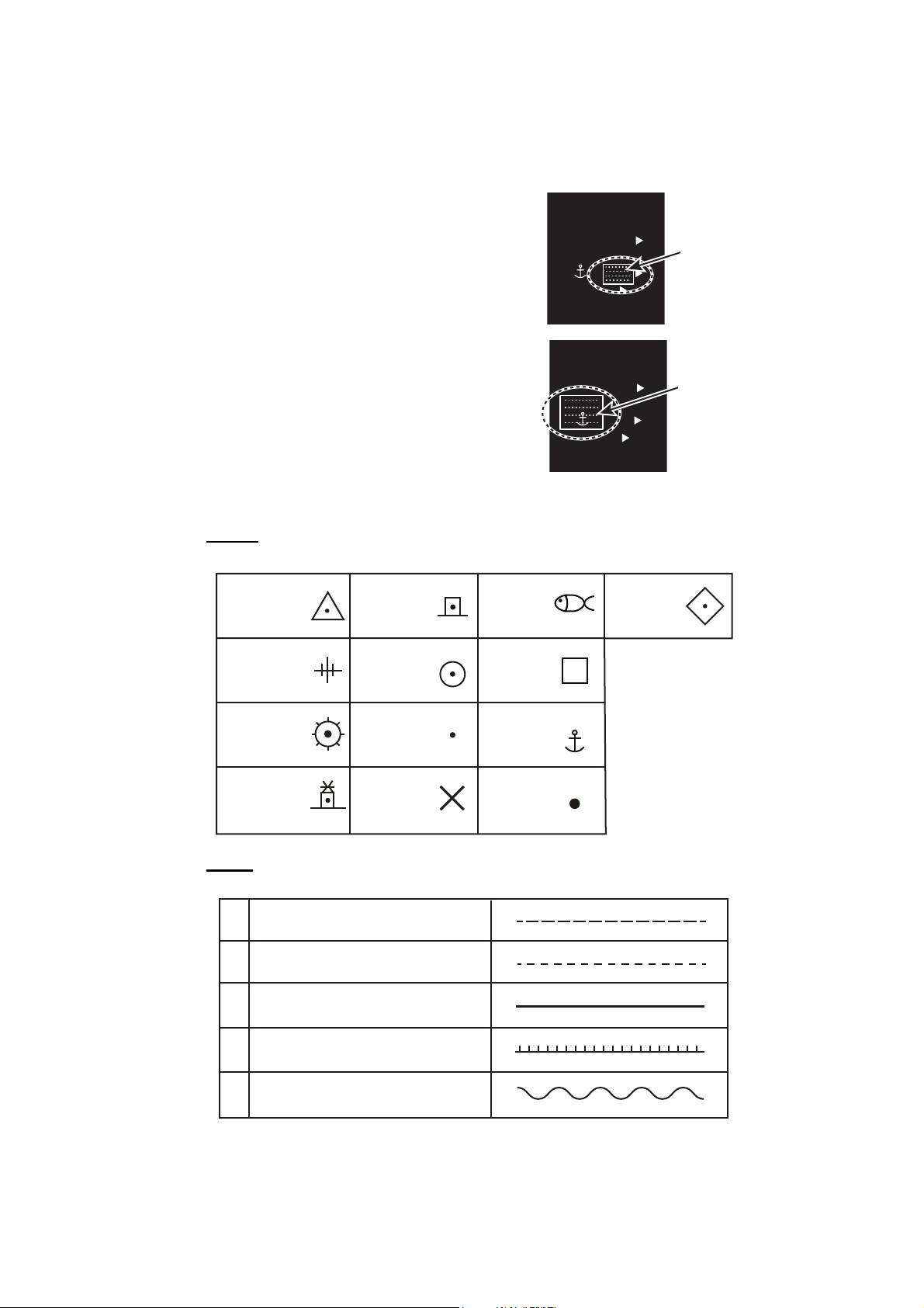
O
MARK
Mark color icon
O
MARK
Triangle
Lighthouse 1
Lighthouse 2
Lighthouse 3
Circle
Small dot
Cross
Fish
Square
Anchor
Dot
Dash with
3 bar-line
Diamond
Dashed line
Coast line
Contour line / Prohibited areas
Cable
Long dashed line
1
2
3
4
5
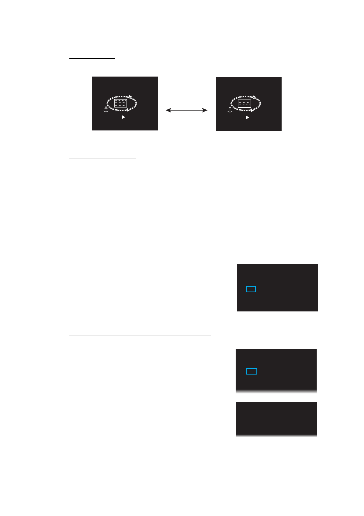
4.3 How to Enter Marks, Lines
4.3.1 How to enter a mark, line with at the cursor position
1. Click the mark color icon to select the required color for the mark.
2. Highlighting the [MARK] icon then rotate
the setting knob to select a mark.
MENU
BARGE
2
MARK
BRL2-3
ECHO
MENU
BARGE
2
MARK
BRL2-3
ECHO
ON
WHT
ON
CYA
GRN
ON
WHT
OFF
CYA
GRN
D
[MARK] icon
D
3. Press the left button on the appropriate mark to decide the mark (or line) shape.
Marks
4-2
Lines
4. Press the left button. For lines, press the left button on the next point of the line
then repeat this operation to complete the line.
5. Press the right button to quit.

4. RADAR MAP
[MARK ICON]
1 BACK
2 [CREATE]
3 OWN SHIP
[MARK/LINE INFO]
1 BACK
2 MARK/LINE INFO
CURRENT NUMBER
:100
TOTAL CAPACITY:5000
4.3.2 How to enter a mark by latitude and longitude position input
This function is not available for entering lines.
1. Right-click the [MARK] icon to show the
[MARK ICON] window.
2. Click [CREATE] to show the [CREATE] window.
3. Click [ENTER BY LL].
4. The cursor is on the far left-hand digit on the latitude line. Rotate the setting knob
to click a numeral. The cursor moves to the next digit. Enter other numbers similarly.
5. Right-click the last digit to finish.
4.3.3 How to enter a mark at current position
This function is not available for entering lines.
1. Right-click the [MARK] icon to show the [MARK ICON] window.
2. Click [OWN SHIP].
[CREATE]
1 BACK
2 ENTER BY LL
00°00. 000 N
000°00. 000 E
3 CREATE
4.4 Mark/Line information
You can confirm the number of marks and lines which you have entered.
1. Open [MAIN MENU], click [RADAR MAP].
2. Click [MARK/LINE INFO] to open the information window.
4-3
4. RADAR MAP
Display icon: [ON]
Display icon: [OFF]
F
MARK
F
MARK
Click
[MARK]
1 BACK
2 DELETE
NO/YES
1 BACK
2 MAP ALIGN
OFF/ON
3 [MARK/LINE INFO]
4 [DATA DELETE]
[RADAR MAP]
4.5 How to Show, Hide Marks on the Screen
By menu icon
Click the mark display icon to show or hide the marks.
MENU
BARGE
ON
2WHT
MARK
ON
CYA
BRL2-3
ECHO
GRN
DOCK OF
By [DISPLAY] menu
This menu is available in the [RIVER] mode only.
1. Open [MAIN MENU], click the [DISPLAY] menu.
2. Click [MARK/LINE].
3. Click [ON] or [OFF].
4.6 How to Delete Marks, Lines
How to delete marks, lines individually
MENU
ON
BARGE
2WHT
MARK
OFF
CYA
BRL2-3
ECHO
GRN
DOCK OF
1. Right-click the mark to delete.
2. Click [DELETE].
3. Click [YES].
How to delete marks, lines by color, shape
1. Open [MAIN MENU], click [RADAR MAP] to show
the [RADAR MAP] menu.
2. Click [DATA DELETE].
[DATA DELETE]
1 BACK
2 [MARK/LINE DELETE]
3 [BARGE DELETE]
4-4

4. RADAR MAP
3. Click [MARK/LINE DELETE].
[MARK/LINE DELETE]
1 BACK
2 [SHAPE DELETE]
3 [COLOR DELETE]
4 MARK/LINE ALL DELETE
NO/YES
4. Click the sort to delete.
[SHAPE DELETE]: Select the shape to delete then
select [YES] in [DELETE].
[COLOR DELETE]: Select the color to delete then select [YES] in [DELETE].
5. Click [DELETE].
6. Click [YES].
7. Click outside the menu window to close the menu.
How to delete all marks, lines
1. Open [MAIN MENU], click [RADAR MAP] to show the [RADAR MAP] menu.
2. Click [DATA DELETE].
3. Click [MARK/LINE DELETE].
4. Click [MARK/LINE ALL DELETE].
5. Click [YES].
6. Click outside the menu window to close the menu.
4.7 How to Align the Radar Map
When the map is not overlaid on the radar picture correctly, you can align the map with
the [MAP ALIGN] menu.
1. Open [MAIN MENU], click [RADAR MAP].
[RADAR MAP]
1 BACK
2 MAP ALIGN
OFF/ON
3 [MARK/LINE INFO]
4 [DATA DELETE]
2. Click [MAP ALIGN].
3. Click [ON] to align the radar echo to the radar map. The cursor moves the center
of the radar display. The mark symbols are moved in conjunction with the cursor
movement.
4. Click anywhere in the radar display to complete the alignment.
4-5
 Loading...