

Furuno USA 9ZWRTR122 User Manual

• A magnetic compass will be affected if the hub is placed too close to the compass.
Observe the compass safe distances in the SAFETY INSTRUCTIONS to prevent
compass malfunction.
1.10 Junction Box (option)
If the length of the antenna cable is more than 100 m, junction boxes are required. Install the boxes in a location protected from the weather, because their waterproofing
standard is IPX3.
Fasten the junction boxes to the mounting location with four sets of M8 bolts and nuts.
See the outline drawing for mounting dimensions.
1. INSTALLATION
1-29

1. INSTALLATION
This page is intentionally left blank.
1-30
2. WIRING
50Hz
60Hz
2.1 Overview
Cable considerations
To lessen the chance of picking up electrical interference where possible, avoid routing
the antenna cable (power and LAN lines) near other onboard electrical equipment (radars, TX radio antennas, etc.). Also avoid running the cable in parallel with power cables. When crossing with other cable, the angle must be 90° to minimize the magnetic
field coupling.
The antenna cable between the antenna and processor units is available in lengths of
15 m, 30 m, 40 m, and 50 m. Whatever length is used, it must be unbroken; namely, no
splicing allowed. Use the antenna cable as short as possible to minimize attenuation of
the signal.
The radar must be connected to an emergency power source, as required by SOLAS II-
1.
About wiring
• The length of LAN cables must be within 50 m.
• Use Cat5e or Cat6 LAN cable for the network if available locally.
• If LAN cables are not available locally, use the optional LAN cables (FR-FTPC-CY for
sensor network, DTI-C5E350 VCV for gateway network).
• If extension or division of the DVI or RGB cables is necessary, use the dividers shown
below.
• DVI cable divider: DVI-12A (maker: IMAGENICS)
• RGB divider: CIF-12H, DD-106 or WBD-14F (maker: IMAGENICS)
• Make sure that the ground wires are connected between the ground terminals on
each equipment and the ship’s earth.
• Pass the cables through the specified clamp or the locking wire saddle.
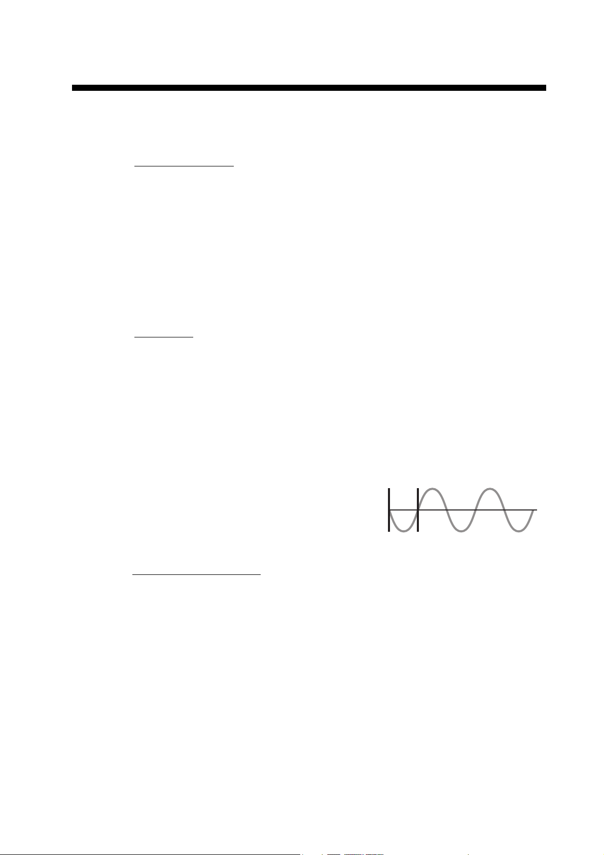
• If a UPS (user supply) is connected to this equipment, be sure that the grounding lamp does not
light.
• The output from the UPS must be a sine wave, as
shown in the figure to the right.
About network construction
• Use the optional Switching Hub HUB-100 to connect the sensor networks. For the
gateway networks, use the optional Intelligent Hub HUB-3000.
• Do not connect the ship’s LAN network to the optional HUBs. Also, commercial PCs
cannot be connected to the gateway network, other than for maintenance.
• To connect the FAR-2xx7 series via LAN network, use the Gateway network.
• This unit does not support IGMP snooping or CGMP enabled switch.
• This unit does not have a router or repeater hub function.
• The Switching HUB HUB-100 does not support IGMP snooping or GCMP enabled
switch.
2-1
2. WIRING
DVI-D/D SINGLE LINK
5/10 m
DTI-C5E 350 VCV
10/20/30 m
DVI-BNCX5+GND-L2.0
2 m
FR-FTPC-CY
10/20/30 m
100-230 VAC
1ø, 50-60 Hz
100-230 VAC
100-230 VAC
Transformer
440 VAC
1ø, 50-60 Hz
Switching
HUB
HUB-100
Control Unit
RCU-016
Monitor Unit
MU-190 or
MU-231 or
MU-270W
VDR
(IEC61162-450 format)
VDR
(Analog RGB)
Intelligent Hub
HUB-3000
Gyrocompass
(AD-10 format)
Gyrocompass
(IEC61162 format)
AIS Transponder
EPFS (GPS)
Sub monitor
Antenna Cable (LAN+serial)
RW-00135
15/30/40/50 m
USB Device
100-115/220-230 VAC
1ø, 50-60 Hz
(for de-icer)
PROCESSOR
UNIT
RPU-025
ANTENNA
UNIT
Control Unit
RCU-014
or
RCU-015
XH10P-W-6P
2.3/10/20/30 m
XH10P-W-5P
TTYCSLA-4
TTYCSLA-4
AMS
(IEC61162 format)
TTYCSLA-4
AMS
(Contact)
Sub Monitor 1
of ECDIS
TTYCSLA-7
RW-4864
1/5/10/15 m
Sub Monitor 2
of ECDIS
RW-4864
1/5/10/15 m
ECDIS
TTYCSLA-4
TTYCSLA-1Q
SDME (Speed log)
TTYCSLA-1Q
TTYCSLA-1Q
100-230 VAC
DPYC-1.5
DPYC-1.5
DPYC-1.5
DPYC-2.5
S03-92-* (8P)
15/30/40/50 m
DPYCY-1.5
:
Standard supply
:
Optional or local supply
1.5/10/20/30 m
max. 5 m
(For mouse)
USB Device
max. 2 m
(For chart update)
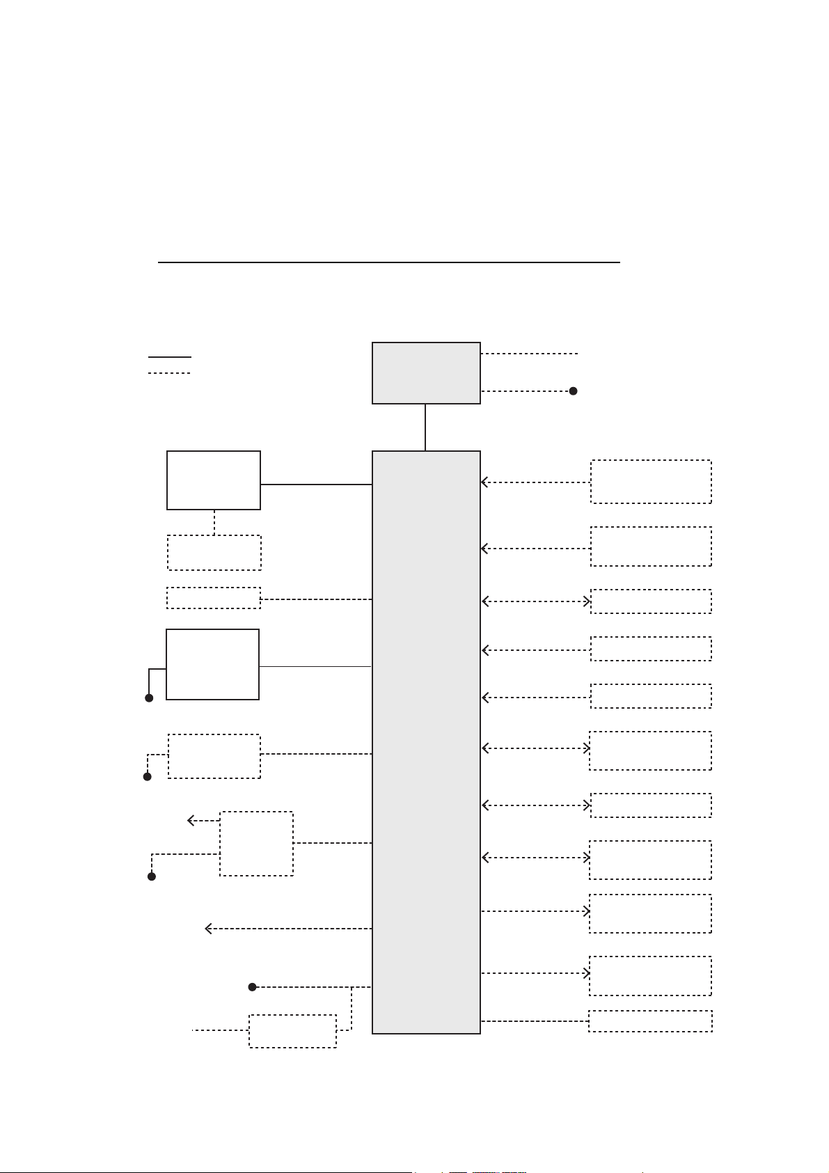
2.1.1 Standard wiring
A Cat 5e LAN cable (RW-00135, RW00339) connects between the Antenna Unit
(Power Supply Unit for FAR-2x58) and the Processor Unit. The maximum length of the
cabling between the Processor Unit and the antenna unit is 80 m.
Retrofit (using antenna cable RW-9600/4896) or foremast installation is also possible,
with the installation of a pair of LAN Signal Converters, one in the antenna unit, the
other in the Processor Unit. See section 2.10.
X-band/S-band (TR-UP) radars for FAR2x18/2x28/2x38 radars
The appropriate radars are FAR-22x8(-BB), FAR-23x8, FAR-22x8S(-BB), FAR23x8S(-NXT) and FAR-2238S-NXT(-BB).
2-2
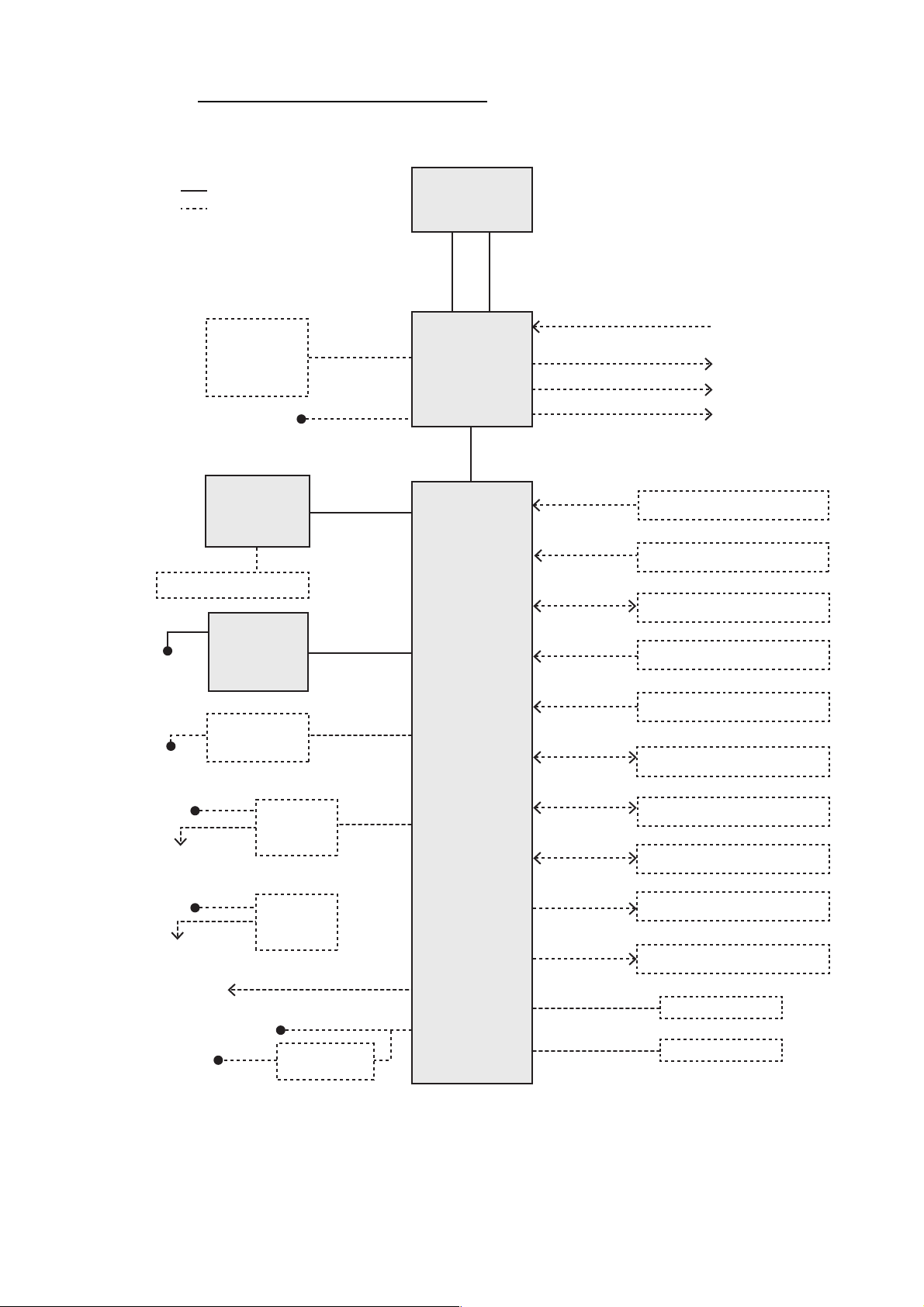
X-band radars for FAR2x58 radars
100-230 VAC
1ø, 50-60 Hz
DVI-BNCX5+GND-L2.0
2 m
100-230 VAC 1ø, 50-60 Hz
Transformer
440 VAC
1ø, 50-60 Hz
VDR
(Analog RGB)
DPYC-1.5
DPYC-2.5
Antenna Cable*
5
• RW-0013 15/20/30/50 m
• RW-0030 15/20/30/50 m
• 03CA00099 70 m
Motor Cable
TPYCY-2.5
:
Standard supply
:
Optional or local supply
100-115/220-230 VAC
1ø, 50-60 Hz
External radar
Sub monitor 2
Power Supply
Unit
PSU-019
Antenna Unit
Processor
Unit
RPU-025
DVI-D/D S-LINK
5 m (option: 10 m)
XH10P-W-6P
10/20/30 m
DTI-C5E
350 VCV
10/20/30 m
FR-FTPC-CY
10/20/30 m
Sensors
(IEC61162-450 format)
Gyrocompass (AD-10 format)
Gyrocompass (IEC61162 format)
AIS Transponder
EPFS (GPS)
Antenna Cable (LAN+serial)
RW-00339
1.5/5/10/15/30/40/50 m
VDR
(IEC61162-450 format)
TTYCSLA-4
RW-4864 10/15 m
RW-00136 50/70 m
RW-4864 10/15 m
RW-00136 50/70 m
RW-4864 10/15 m
RW-4864 10/15 m
Sub monitor 3
Sub monitor 1
TTYCSLA-4
AMS (IEC61162 format)
TTYCSLA-4
AMS (Contact)
Sub Monitor 1 of ECDIS
TTYCSLA-7
RW-4864
1/5/10/15 m
Sub Monitor 2 of ECDIS
RW-4864
1/5/10/15 m
ECDIS
TTYCSLA-4
TTYCSLA-1Q
SDME (Speed log)
TTYCSLA-1Q
TTYCSLA-1Q
DPYC-1.5
DPYC-1.5
100-230 VAC
1ø, 50-60 Hz
100-230 VAC
1ø, 50-60 Hz
Monitor Unit
MU-190/
MU-231/
MU-270W
Control Unit
RCU-014/
RCU-015/
RCU-031
Intelligent Hub
HUB-3000
Switching
HUB
HUB-100
DPYC-1.5
100-230 VAC
1ø, 50-60 Hz
Switching
HUB
HUB-100
Control Unit
RCU-014/
RCU-015/
RCU-031
XH10P-W-6P
10/20/30 m
XH10P-W-5P
1.5/10/20/30 m
Control Unit RCU-016
OR
USB Device
USB Device
max. 2 m
(For chart update)
max. 5 m
(For mouse)
The appropriate radars are FAR-2258(-BB), FAR-2358.
2. WIRING
2-3
2. WIRING
DVI-D/D SINGLE LINK
5/10 m
DTI-C5E 350 VCV
10/20/30 m
FR-FTPC-CY
10/20/30 m
100-230 VAC
1ø, 50-60 Hz
100-230 VAC
100-230 VAC
Transformer
440 VAC
1ø, 50-60 Hz
Switching
HUB
HUB-100
Control Unit
RCU-016
Monitor Unit
MU-190 or
MU-231 or
MU-270W
VDR
(IEC61162-450 format)
VDR
(Analog RGB)
Intelligent Hub
HUB-3000
Gyrocompass
(AD-10 format)
Gyrocompass
(IEC61162 format)
AIS Transponder
EPFS (GPS)
Sub display
Antenna Cable (LAN+serial)
RW-00135
15/30/40/50 m
100-115/220-230 VAC
1ø, 50-60 Hz
(for de-icer)
PROCESSOR
UNIT
RPU-025
ANTENNA
UNIT
TRANSCEIVER
UNIT
RTR-108 (X-band)
or
RTR-109 (S-band)
Control Unit
RCU-014
or
RCU-015
XH10P-W-6P
2.3/10/20/30 m
1.5/10/20/30 mXH10P-W-5P
TTYCSLA-4
TTYCSLA-4
AMS
(IEC61162 format)
TTYCSLA-4
AMS
(Contact)
Sub Monitor 1
of ECDIS
TTYCSLA-7
RW-4864
1/5/10/15 m
Sub Monitor 2
of ECDIS
RW-4864
1/5/10/15 m
ECDIS
TTYCSLA-4
TTYCSLA-1Q
SDME (Speed log)
TTYCSLA-1Q
TTYCSLA-1Q
100-230 VAC
DPYC-1.5
DPYC-1.5
DPYC-1.5
DPYC-2.5
S03-92-* (8P)
15/30/40/50 m
DPYCY-1.5
TTYCYSLA-10
15/30/40/50 m
S-band
LHPX-20-ASSY or WF-H50-7S, 20/30 m
X-band
FR-9 Waveguide, 20/30/50 m
:
Standard supply
:
Optional or local supply
DVI-BNCX5+GND-L2.0
2 m
USB Device
max. 5 m
(For mouse)
USB Device
max. 2 m
(For chart update)
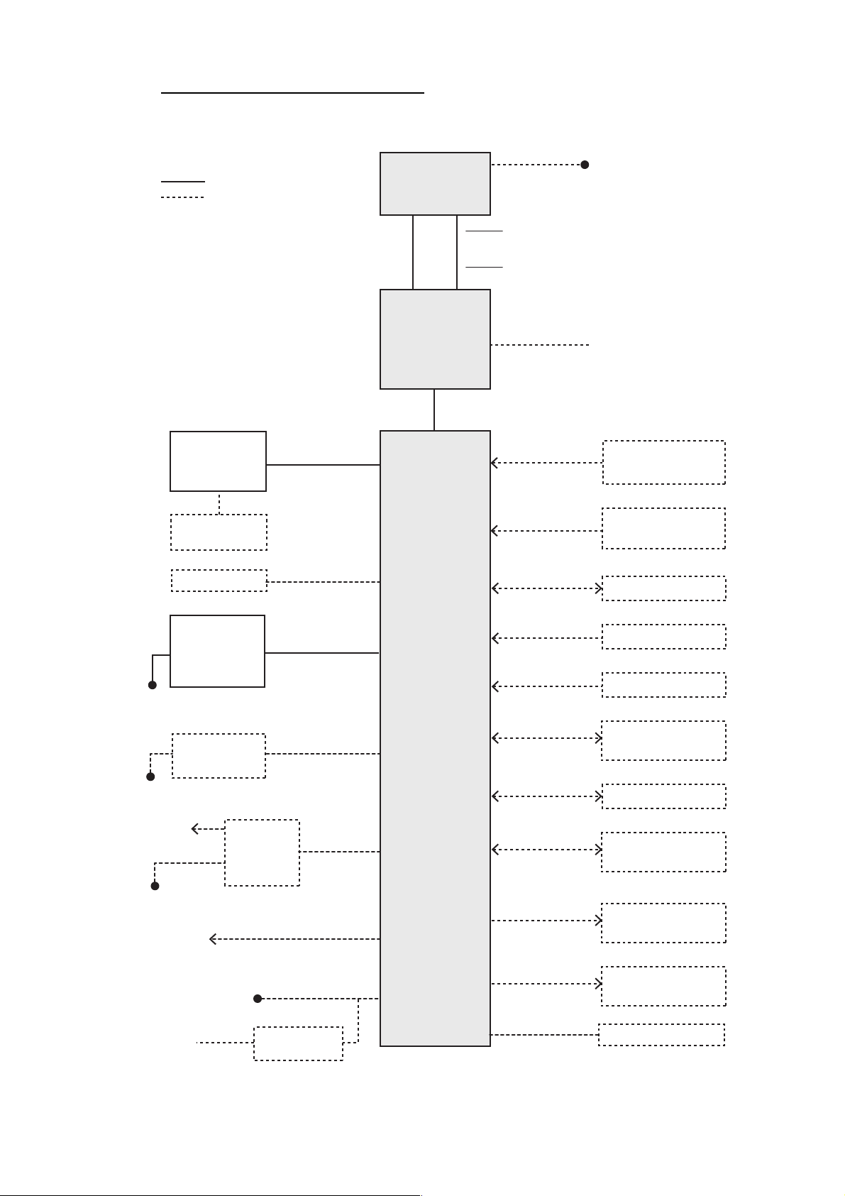
X-band/S-band (TR-DOWN) radars
The appropriate radars are FAR-2328W and FAR-2338SW.
2-4
 Loading...