

Furuno USA 9ZWRTR120 User Manual

OPERATOR'S MANUAL
MARINE RADAR
MODEL 1815
www.furuno.com
IMPORTANT NOTICES
Cd
Ni-Cd Pb
General
• This manual has been authored with simplified grammar, to meet the needs of international users.
• The operator of this equipment must read and follow the descriptions in this manual.
Wrong operation or maintenance can cancel the warranty or cause injury.
• Do not copy any part of this manual without written permission from FURUNO.
• If this manual is lost or worn, contact your dealer about replacement.
• The contents of this manual and equipment specifications can change without notice.
• The example screens (or illustrations) shown in this manual can be different from the screens you
see on your display. The screens you see depend on your system configuration and equipment
settings.
• Save this manual for future reference.
• Any modification of the equipment (including software) by persons not authorized by FURUNO will
cancel the warranty.
• The following concern acts as our importer in Europe, as defined in DECISION No 768/2008/EC.
- Name: FURUNO EUROPE B.V.
- Address: Ridderhaven 19B, 2984 BT Ridderkerk, The Netherlands
• All brand and product names are trademarks, registered trademarks or service marks of their
respective holders.
How to discard this product
Discard this product according to local regulations for the disposal of industrial waste. For disposal in
the USA, see the homepage of the Electronics Industries Alliance (http://www.eiae.org/) for the
correct method of disposal.
How to discard a used battery
Some FURUNO products have a battery(ies). To see if your product has a battery, see the chapter on Maintenance. Follow the instructions below if a battery is used. Tape the + and - terminals
of battery before disposal to prevent fire, heat generation caused by short circuit.
In the European Union
The crossed-out trash can symbol indicates that all types of batteries
must not be discarded in standard trash, or at a trash site. Take the
used batteries to a battery collection site according to your national legislation and the Batteries Directive 2006/66/EU.
In the USA
The Mobius loop symbol (three chasing arrows) indicates that
Ni-Cd and lead-acid rechargeable batteries must be recycled.
Take the used batteries to a battery collection site according to
local laws.
In the other countries
There are no international standards for the battery recycle symbol. The number of symbols can
increase when the other countries make their own recycle symbols in the future.
i
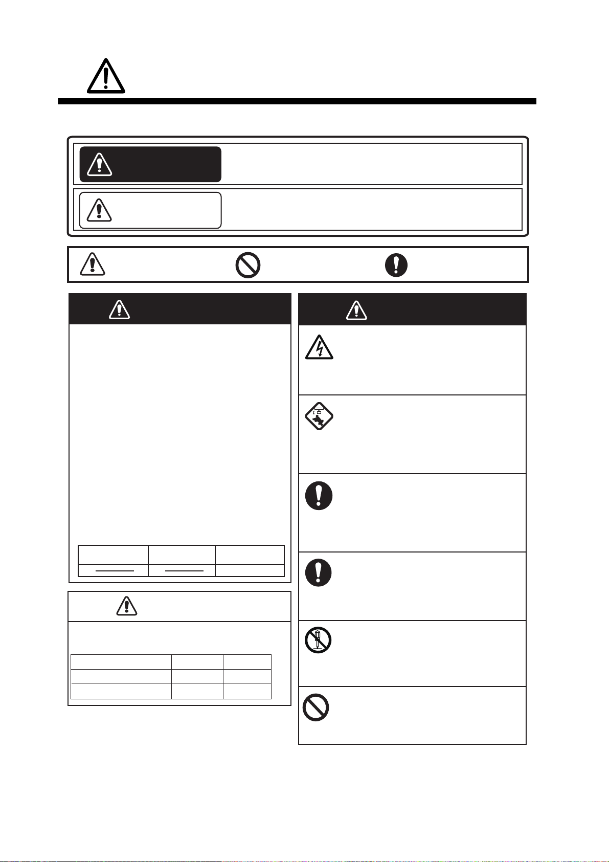
SAFETY INSTRUCTIONS
WARNING
Indicates a condition that can cause death or serious
injury if not avoided.
CAUTION
Indicates a condition that can cause minor or moderate
injury if not avoided.
Warning, Caution
Mandatory Action
Prohibitive Action
Read these safety instructions before you operate or install the equipment.
WARNING
Radio Frequency Radiation Hazard
The radar antenna sends the electromagnetic
radio frequency (RF) energy. This energy can
be dangerous to you, especially your eyes.
Do not look at the radiator or near the
antenna when the antenna is rotating.
The distances at which RF radiation levels of
100 W/m
2
, 50 W/m2 and 10 W/m2 exist are
shown in the table.
Note: If the antenna unit is installed at a
close distance in front of the wheel house,
prevent the transmission in that area to
protect passengers and crew from microwave
radiation. Set the [Sector Blanks] in the
[System] menu.
Distance to
100 W/m
2
point
Distance to
50 W/m2 point
Distance to
10 W/m2 point
Worst case 1.1 m
Standard
Steering
Display unit
0.45 m
0.30 m
CAUTIONCAUTION
M1815 Antenna unit
1.70 m
1.05 m
Unit
Observe the following compass safe distances to
prevent deviation of a magnetic compass.
WARNING
Do not open the equipment.
The equipment uses high voltage that
can cause electrical shock. Refer any
repair work to a qualified technician.
Before turning on the radar, be sure
no one is near the antenna.
Prevent the potential risk of being
struck by the rotating antenna, which
can result in serious injury or death.
If water leaks into the equipment or
something is dropped into the
equipment, immediately turn off the
power at the switchboard.
Fire or electrical shock can result.
If the equipment is giving off smoke
or fire, immediately turn off the
power at the switchboard.
Fire or electrical shock can result.
Do not disassemble or modify the
equipment.
Fire, electrical shock or serious injury
can result.
Do not place operate the equipment
with wet hands.
Electrical shock can result.
ii
SAFETY INSTRUCTIONS
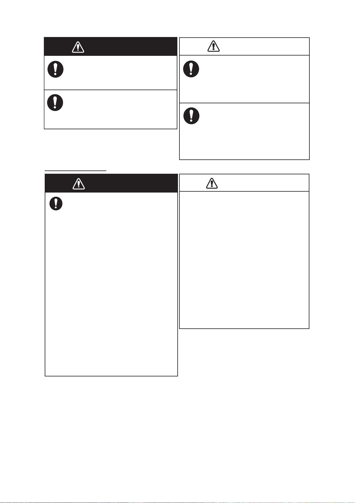
WARNING
Usethe correct fuse.
Use of a wrong fuse can result in fire or
damage to the equipment.
Do not place liquid-filled containers
on the equipment.
Fire or electrical shock can result if a
liquid spills into the equipment.
CAUTIONCAUTION
The guard zone alarm is an effective aid
to anti-collison.
Its use does not relieve the operator of the
responsibility to keep a vigilant watch on
his or her surroundings.
The data presented by this equipment
is intended as a source of navigation
information.
The prudent navigator never relies
exclusively on any one source of
navigation information, for safety of
vessel and crew.
WARNING
The TT function is a valuable aid to
navigation. However, the navigator
must check all aids available to avoid
collision.
- The TT automatically tracks an
automatically or manually acquired
radar target and calculates its course
and speed, indicating them with a
vector. Since the data generated by
the TT depends on the selected radar
targets, the radar must be optimally
tuned for use with the TT, to ensure
required targets will not be lost or
unnecessary targets, like sea returns
and noise, will not be acquired and
tracked.
- A target is not always a landmass,
reef, ship, but can also be returns
from the sea surface and from clutter.
As the level of clutter changes with
the environment, the operator must
correctly adjust the sea and rain
clutter controls and the gain control so
that the target echoes do not dis-
appear from the radar screen.
TT safety information
CAUTIOCAUTION
The plotting accuracy and response of
this TT meets IMO standards. Tracking
accuracy is affected by the following:
•
Tracking accuracy is affected by course
change. One to two minutes is required to
restore vectors to full accuracy after an
abrupt course change. (The actual amount
depends on gyrocompass specifications.)
•
The amount of tracking delay is inversely
proportional to the relative speed of the
target. Delay is approx. 15-30 seconds for
the higher relative speed; approx. 30-60
seconds for the lower relative speed. The
following factors can affect accuracy:
- Echo intensity
- Radar transmission pulse length
- Radar bearing error
- Gyrocompass error
- Course change (own ship and targets)
iii

SAFETY INSTRUCTIONS
WARNING
To avoid electrical shock, do not
remove cover. No user-serviceable
parts inside.
WARNING
Radiation hazard. Only qualified
personnel should work inside scanner.
Confirm that TX has stopped before
opening scanner.
Name: Warning Label 1
Type: 86-003-1011-1
Code No.: 100-236-233-10
Name: Warning Sticker
Type: 0
3-142-3201-0
Code No.:
100-266-890-10
Warning Label(s)
Warning label(s) is(are) attached to the
equipment. Do not remove the label(s). If a
label is missing or damaged, contact a
FURUNO agent or dealer about replacement.
TFT display
The high quality TFT (Thin Film Transistor) LCD
displays 99.99% of its picture elements. The
remaining 0.01% may drop out or light,. However,
this is an inherent property of the TFT; it is not a
sign of malfunction.
iv

TABLE OF CONTENTS
FOREWORD................................................................................................................. viii
SYSTEM CONFIGURATION ...........................................................................................x
1. INSTALLATION .....................................................................................................1-1
1.1 Equipment List............................................................................................................1-1
1.2 How to Install the Display Unit....................................................................................1-1
1.3 How to Install the Antenna Unit ..................................................................................1-3
2. WIRING ..................................................................................................................2-1
2.1 Wiring .........................................................................................................................2-1
3. INITIAL SETTINGS................................................................................................3-1
3.1 How to Select Language ............................................................................................3-1
3.2 How to Select Radar Purpose ....................................................................................3-2
3.3 Initial Settings .............................................................................................................3-2
4. OPTIONAL EQUIPMENT ......................................................................................4-1
4.1 External Buzzer ..........................................................................................................4-1
5. OPERATION ..........................................................................................................5-1
5.1 Controls ......................................................................................................................5-1
5.2 How to Turn the Radar On/Off and Transmit..............................................................5-2
5.3 Display Indications......................................................................................................5-3
5.4 How to Adjust Display Brilliance, Panel Dimmer ........................................................5-4
5.5 Menu Description........................................................................................................5-4
5.6 Tuning.........................................................................................................................5-6
5.7 Display Modes............................................................................................................5-7
5.7.1 How to select the display mode......................................................................5-7
5.7.2 Description of display modes .........................................................................5-8
5.8 How to Select the Range Scale................................................................................5-10
5.9 How to Adjust the Gain (sensitivity)..........................................................................5-10
5.10 How to Reduce the Sea Clutter................................................................................5-11
5.11 How to Reduce the Rain Clutter...............................................................................5-12
5.12 Cursor.......................................................................................................................5-13
5.13 Interference Rejector................................................................................................5-14
5.14 Noise Rejector..........................................................................................................5-15
5.15 How to Measure the Range to a Target ...................................................................5-15
5.15.1 How to adjust range ring brilliance ...............................................................5-15
5.15.2 How to measure the range with a VRM........................................................5-16
5.15.3 How to select VRM unit ................................................................................5-17
5.16 How to Measure the Bearing to a Target..................................................................5-18
5.16.1 How to measure the bearing with an EBL ....................................................5-18
5.16.2 EBL reference ..............................................................................................5-19
5.17 How to Measure the Range and Bearing Between Two Targets .............................5-20
5.18 Target Alarm.............................................................................................................5-21
5.18.1 How to set a target alarm zone ....................................................................5-21
5.18.2 How to stop the audio alarm.........................................................................5-22
5.18.3 How to select the alarm type ........................................................................5-22
5.18.4 How to sleep a target alarm temporarily.......................................................5-23
5.18.5 How to deactivate a target alarm..................................................................5-23
5.18.6 How to select the target strength which triggers a target alarm ...................5-23
5.18.7 How to turn the buzzer on/off .......................................................................5-23
v

TABLE OF CONTENTS
5.19 How to Off-center the Display ..................................................................................5-24
5.19.1 How to select the off-center mode ...............................................................5-24
5.19.2 Off-center the display................................................................................... 5-25
5.20 Zoom ........................................................................................................................5-26
5.20.1 Zoom mode.................................................................................................. 5-26
5.20.2 How to zoom ................................................................................................5-27
5.21 Echo Stretch.............................................................................................................5-29
5.22 Target Trails .............................................................................................................5-29
5.22.1 Trail time ......................................................................................................5-29
5.22.2 Trail mode ....................................................................................................5-30
5.22.3 Trail gradation ..............................................................................................5-31
5.22.4 Trail color .....................................................................................................5-31
5.22.5 Trail level...................................................................................................... 5-32
5.22.6 How to restart, stop the trails .......................................................................5-32
5.22.7 Narrow trails ................................................................................................. 5-33
5.22.8 Your ship trail ...............................................................................................5-33
5.22.9 How to erase all trails................................................................................... 5-33
5.23 How to Program the FUNC Key............................................................................... 5-34
5.24 Echo Average...........................................................................................................5-34
5.25 Wiper........................................................................................................................ 5-35
5.26 Characteristics Curve...............................................................................................5-36
5.27 Own Ship and Barge Markers.................................................................................. 5-36
5.27.1 How to show the own ship marker ...............................................................5-36
5.27.2 How to show the barge marker ....................................................................5-37
5.28 Watchman ................................................................................................................5-38
5.29 Alarm Message ........................................................................................................5-39
5.30 Color Selections ....................................................................................................... 5-41
5.30.1 Preset colors ................................................................................................5-41
5.30.2 Custom colors ..............................................................................................5-41
5.31 Echo Area ................................................................................................................5-42
5.32 Initial Sub Menu .......................................................................................................5-43
5.32.1 How to open the Initial sub menu................................................................. 5-43
5.32.2 Description of Initial sub menu..................................................................... 5-43
5.33 Sector Blank.............................................................................................................5-45
5.34 Other Menu Items ....................................................................................................5-46
5.34.1 Brill/Color menu............................................................................................5-46
5.34.2 Display menu ...............................................................................................5-48
5.34.3 Echo menu................................................................................................... 5-48
5.34.4 Units menu................................................................................................... 5-49
5.35 Navigation Data........................................................................................................5-50
5.35.1 Navigation data during standby....................................................................5-50
5.35.2 Navigation data at the bottom of the screen ................................................ 5-50
5.36 Waypoint Marker ...................................................................................................... 5-52
5.37 How to Send the Target Position and Enter the Origin Mark ...................................5-53
6. HOW TO INTERPRET THE RADAR DISPLAY.....................................................6-1
6.1 General ......................................................................................................................6-1
6.1.1 Minimum and maximum ranges..................................................................... 6-1
6.1.2 Radar resolution.............................................................................................6-2
6.1.3 Bearing accuracy ...........................................................................................6-3
6.1.4 Range measurement...................................................................................... 6-3
6.2 False Echoes .............................................................................................................6-3
6.2.1 Multiple echoes ..............................................................................................6-3
6.2.2 Sidelobe echoes.............................................................................................6-4
6.2.3 Virtual image ..................................................................................................6-4
6.2.4 Shadow sector ...............................................................................................6-5
vi

TABLE OF CONTENTS
6.3 SART (Search and Rescue Transponder)..................................................................6-6
6.3.1 SART description ...........................................................................................6-6
6.3.2 General remarks on receiving SART..............................................................6-7
6.4 RACON.......................................................................................................................6-8
7. TT OPERATION.....................................................................................................7-1
7.1 Precautions for Use....................................................................................................7-1
7.2 Controls for Use with TT.............................................................................................7-1
7.3 TT Display On/Off.......................................................................................................7-2
7.4 How to Acquire and Track the Targets.......................................................................7-2
7.4.1 Manual acquisition..........................................................................................7-2
7.4.2 Automatic acquisition .....................................................................................7-3
7.5 How to Stop the Tracking of TT..................................................................................7-3
7.5.1 How to stop the tracking of selected targets ..................................................7-3
7.5.2 How to stop the tracking of all targets ............................................................7-3
7.6 Vector Attributes.........................................................................................................7-4
7.6.1 What is a vector?............................................................................................7-4
7.6.2 Vector time and vector reference ...................................................................7-4
7.6.3 Vector of your ship .........................................................................................7-5
7.7 Past Position Display (target past position)................................................................7-6
7.8 TT Data.......................................................................................................................7-7
7.9 CPA/TCPA Alarm .......................................................................................................7-8
7.10 Proximity Alarm ..........................................................................................................7-9
7.11 Lost Target ...............................................................................................................7-10
7.12 Symbol Color............................................................................................................7-10
8. AIS OPERATION ...................................................................................................8-1
8.1 AIS Display On/Off .....................................................................................................8-1
8.2 AIS Symbols...............................................................................................................8-2
8.3 Activating, Sleeping Targets.......................................................................................8-2
8.4 AIS Target Data..........................................................................................................8-3
8.5 How to Sort Targets....................................................................................................8-4
8.6 Display Range ............................................................................................................8-4
8.7 How to Display the Targets within a Specific Sector ..................................................8-5
8.8 Number of Targets to Display.....................................................................................8-5
8.9 Vector Attributes.........................................................................................................8-6
8.9.1 What is a vector?............................................................................................8-6
8.9.2 Vector time and vector reference ...................................................................8-6
8.10 Past Position Display (target past position)................................................................8-7
8.11 CPA/TCPA Alarm .......................................................................................................8-8
8.12 Proximity Alarm ..........................................................................................................8-9
8.13 Lost Target .................................................................................................................8-9
8.14 Symbol Color............................................................................................................8-10
8.15 How to Ignore Slow Targets .....................................................................................8-10
9. GPS OPERATION .................................................................................................9-1
9.1 Navigator Mode ..........................................................................................................9-1
9.2 Datum.........................................................................................................................9-2
9.3 WAAS Setup...............................................................................................................9-3
9.4 Satellite Monitor..........................................................................................................9-4
9.5 Self Test .....................................................................................................................9-5
9.6 Cold Start....................................................................................................................9-6
10. MAINTENANCE, TROUBLESHOOTING ............................................................ 10-1
10.1 Preventive Maintenance...........................................................................................10-2
10.2 Fuse Replacement ...................................................................................................10-3
vii

TABLE OF CONTENTS
10.3 Magnetron Life .........................................................................................................10-3
10.4 Simple Troubleshooting ...........................................................................................10-4
10.5 Advanced-level Troubleshooting.............................................................................. 10-5
10.6 Diagnostic Test ........................................................................................................10-7
10.7 LCD Test ..................................................................................................................10-9
10.8 Radar Sensor Test................................................................................................. 10-10
APPENDIX 1 MENU TREE .......................................................................................AP-1
APPENDIX 2 GEODETIC CHART LIST ...................................................................AP-5
APPENDIX 3 DIGITAL INTERFACE.........................................................................AP-7
APPENDIX 4 JIS CABLE GUIDE ...........................................................................AP-14
APPENDIX 5 RADIO REGULATORY INFORMATION ...........................................AP-15
SPECIFICATIONS .....................................................................................................SP-1
INDEX..........................................................................................................................IN-1
viii

FOREWORD
A Word to the Owner of the MODEL1815 Marine Radar
Congratulations on your choice of the FURUNO MODEL1815 Marine Radar. We are confident
you will see why the FURUNO name has become synonymous with quality and reliability.
Since 1948, FURUNO Electric Company has enjoyed an enviable reputation for innovative and
dependable marine electronics equipment. This dedication to excellence is furthered by our extensive global network of agents and dealers.
Your equipment is designed and constructed to meet the rigorous demands of the marine environment. However, no machine can perform its intended function unless properly installed and
maintained. Please carefully read and follow the operation and maintenance procedures set forth
in this manual.
We would appreciate feedback from you, the end-user, about whether we are achieving our purposes.
Thank you for considering and purchasing FURUNO equipment.
Features
The main features are as shown below.
• The main specifications of the MODEL 1815 are outlined in the table below.
Model Output Range
Model 1815 4 kW 36 nm 48 cm, Radome 24 RPM
• The radar is operated with keys, knobs and a Cursorpad.
• Easy-to-view 8.4 inch LCD.
• Echo area display with full screen provides observation of a wider range around the vessel.
• User-programmable function key
• AIS data available with connection of FURUNO AIS Transponder/Receiver.
Program No.
0359375-01.**
**=Minor modification
Antenna unit size
and type
Antenna RPM
ix

FOREWORD
Radar function availability
The Model 1815 is available in two types, [River] (river use) and [Sea] (sea use). Some functions
may not available depending on the type selected See the table below for item and availability.
Type and function availability
Item
Automatic menu closure
Effective radius dot
count
Echo color Select the echo display color
Echo color customiz-
ing
Echo area Select the display area from [Normal] or [Full
Base text display Can show or hide the base text indications.
Range preset Select the radar rang-
Unit defaults
1) range 2) speed
Bearing scale Graduation every 1°, 5°, 10°, 30°, no numeric in-
VRM unit Can set the VRM unit independently from the
Range unit Can change the range unit when transmitting.
AIS symbol color Select the AIS symbol color from [Green], [Red],
Vector reference Select the display mode for the vector from [Rel-
TT number Empty numbers numbered in ascending order
Heading line erasure Heading line, EBL, VRM, guard zone, etc. tem-
Menu closes automatically.
240 dots
Can customize the echo display color.
Screen].
es to use.
1) KM 2) km/h, m/s 1) NM 2) kn
dication, displayed in the effective radius
range unit.
[Blue], [White] or [Black].
ative] or [True].
porarily erased.
River Sea
Type
Page reference
Note on Chinese font: The Chinese font used in this equipment is Ricoh Company Ltd.'s Ricoh
bitmap font.
x
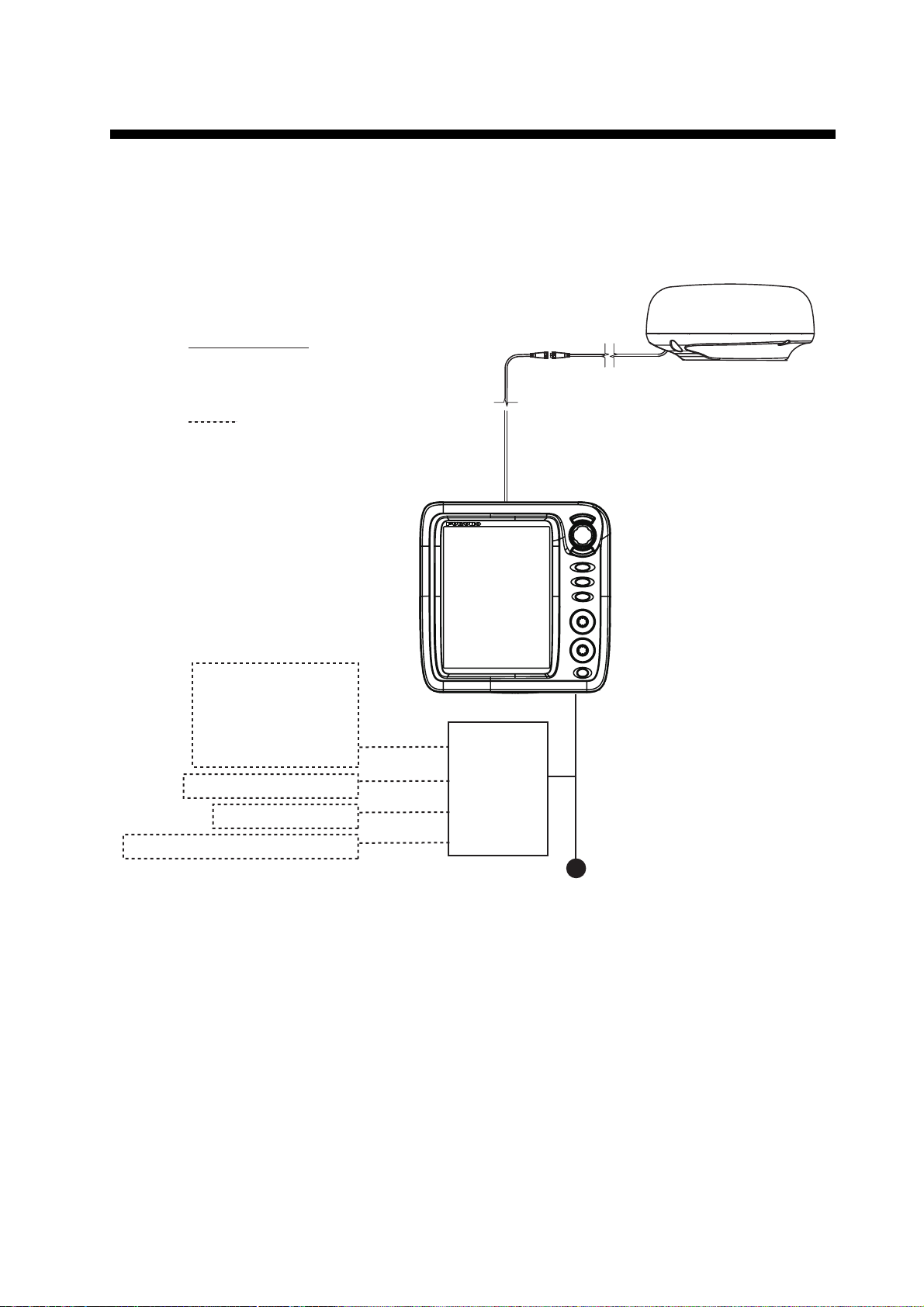
SYSTEM CONFIGURATION
Equipment category
Antenna Unit: Exposed to the weather
Other Equipment : Protected from the weather
GPS navigator
Satellite compass
Heading sensor
Plotter
AIS
DSB transceiver
Power cable 1.4 m
Antenna cable (FRU-CF-FF-XXM) (10/15/20 m)
* Option: CP03-37630 (30 m)
External Buzzer (OP03-21)
Junction Box (FI-5002)
NMEA Data Converter (IF-NMEA2K2)
:Option
Display Unit
RDP-157
MODEL 1815
Antenna Unit
RSB-127-120
RTR-120
Junction Box
(local supply)
Cable Assembly
(FRU-CF-F01)
Power supply
12 - 24 VDC
Basic configuration is shown below with solid line.
xi
 Loading...