

1. INSTALLATION AND WIRING
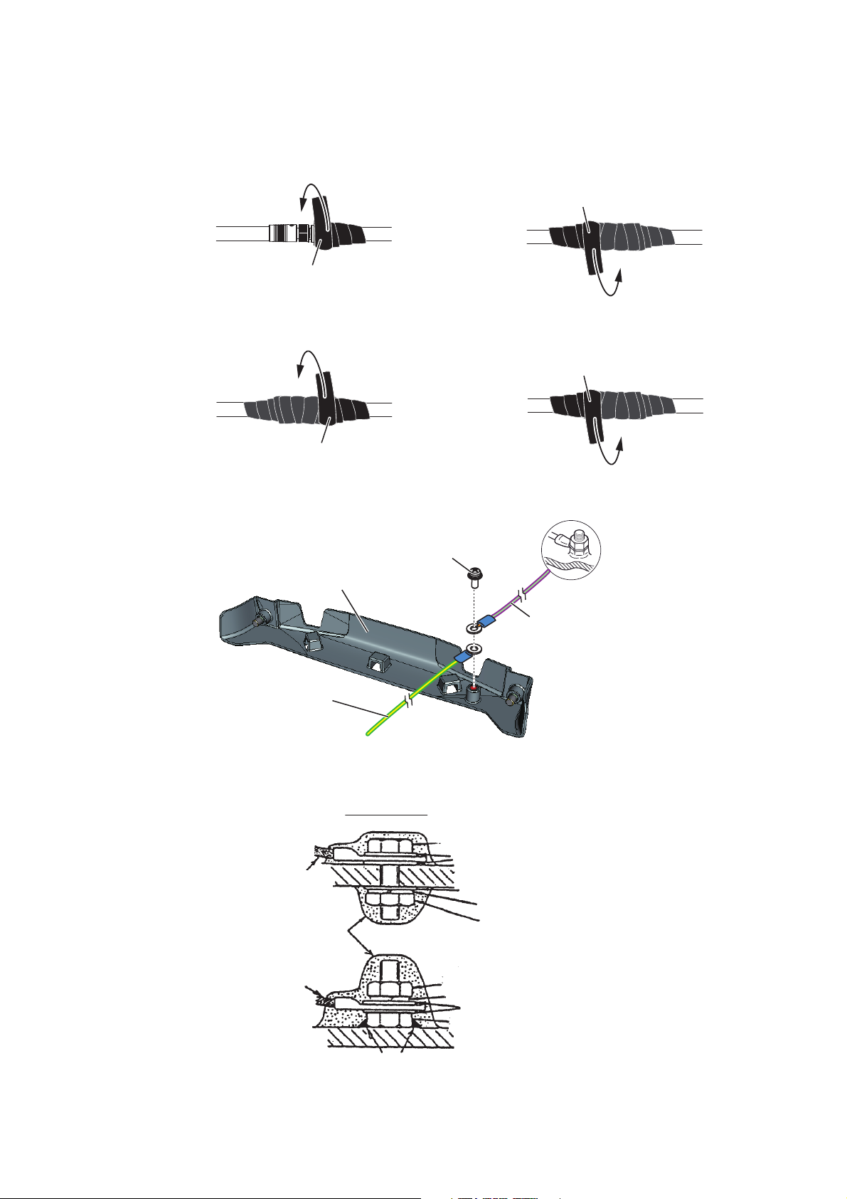
Self-vulcanizing tape
1) Wrap the junction of the connectors
with one layer of self-vulcanizing
tape.
2) Change wrap direction and wrap
one layer of the self-vulcanizing
tape again.
Self-vulcanizing tape
3) Wrap one layer of the vinyl tape over
the self-vulcanizing tape.
Vinyl tape
4) Change wrap direction and wrap one
layer of the vinyl tape again.
Vinyl tape
3. Wrap the junction of the connectors with self-vulcanizing tape and vinyl tape (locally supply) for waterproofing as follows:
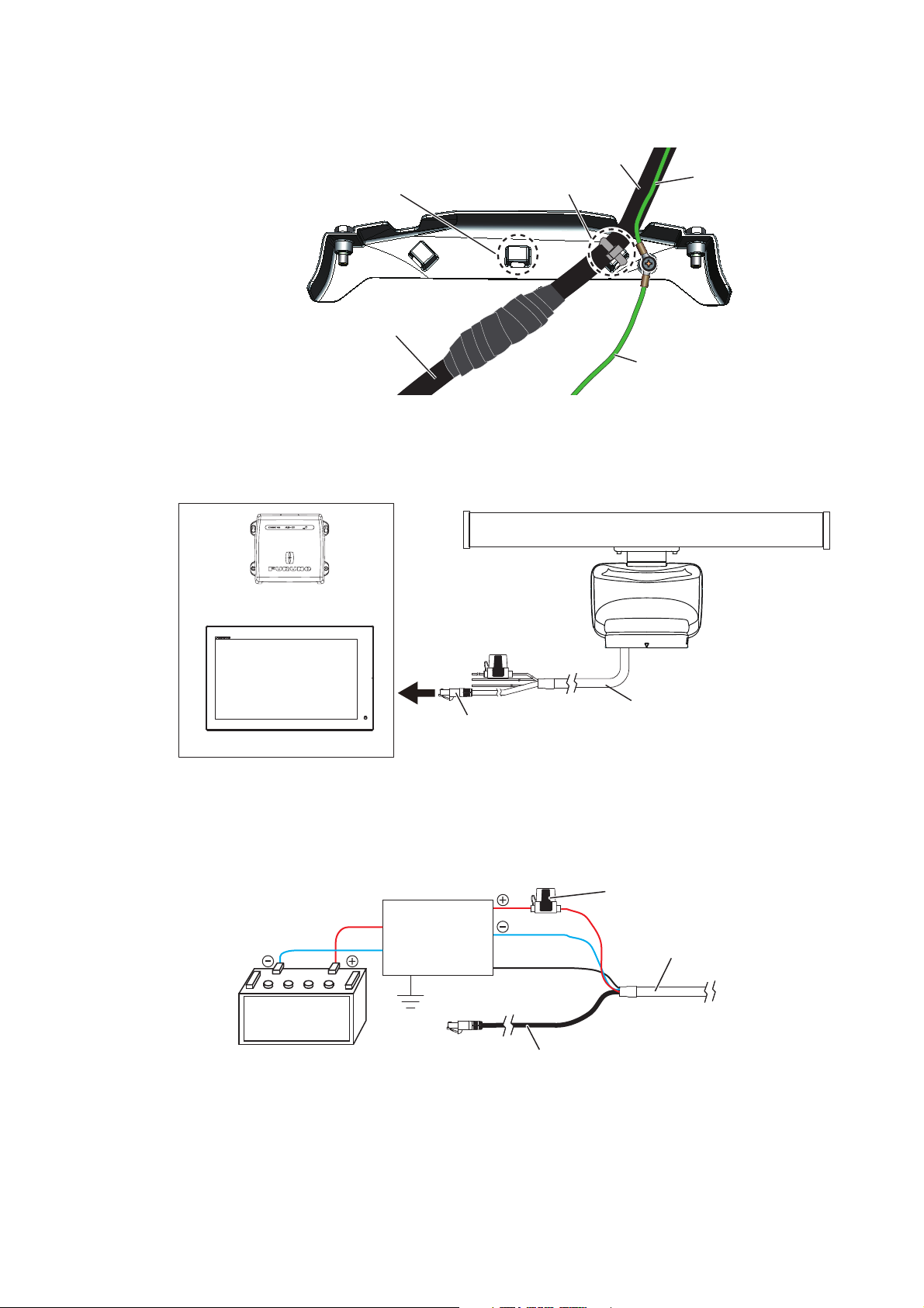
4. As shown in the figure below, attach a ground wire (IV-2sq, local supply) between
the ship’s ground and the screw on the cable cover of the antenna unit.
Ground wire* from
the antenna unit
5. Apply the silicone rubber about ground point of the ship’s ground.
Ground wire
Cable cover
Silecone rubber
Terminal screw*
*: Pre-attached to the cable cover.
Ground point
Hex. bolt
Flat washer
Flat washer
OR
Ship’s ground
Ground wire from
the ship’s ground
Spring washer
Hex. nut
Ground wire
Hex. nut
Spring washer
Flat washer
Hex. nut
Weld here.
Weld here.
11
1. INSTALLATION AND WIRING
Fix the cable with cable tie.Fix the cable with cable tie.
Ground wire from
the ship's ground
Ground wire from
the ship's ground
Power/LAN cablePower/LAN cable
Antenna cableAntenna cable
Ground wire from
the antenna unit
Ground wire from
the antenna unit
If the power/LAN cable is run
through a radar mast and the
bottom of the uni, fix the cable to
this cable clamp.
If the power/LAN cable is run
through a radar mast and the
bottom of the uni, fix the cable to
this cable clamp.
Power/LAN cable
LAN connector
Ethernet HUB
OR
FURUNO Multi Function Display
LAN cable
To antenna unit
Power/LAN cable
Shield
Distribution
switchboard
Ship's battery
(24 VDC)
Fuse holder
6. Fix the power/LAN cable to the cable cover with the cable ties (locally supply) as
shown in the figure below.
7. Reattach the cable cover.
8. Connect the LAN connector of the power/LAN cable to a LAN port on the FURUNO Multi Function Display or Ethernet HUB.
Note: Do not connect the LAN connector to on-board LAN.
9. Connect the power wires to the ship’s battery (24 VDC).
• Red wire: Connect to the positive terminal. The red wire has the fuse holder.
• Blue wire: Connect to the negative terminal.
• Black wire: The black wire is a shielding wire for grounding.
Note 1: The antenna unit has no power switch. Connect the antenna unit to a distribution switchboard with a switch for power control.
Note 2: If the voltage of the ship’s battery is 12 VDC, prepare a DC-to-DC converter whose output current is 10 A or more.
Note 3: The antenna unit cannot accept the input voltage more than 24 VDC.
12
2. INITIAL SETUP
Before turning on the radar, be sure
no one is near the antenna.
Prevent the potential risk of being
struck by the rotating antenna, which
can result in serious injury or death.
WARNING
WARNING
The radar antenna emits
electromagnetic radio frequency (RF)
energy which can be harmful,
particularly to your eyes. Never look
directly into the antenna aperture
from a close distance while the radar
is in operation.
Distances at which RF radiation levels
of 100, 50 and 10 W/m
2
exist are given
in the table below.
0.1m
XN10A
3m0.5m
100 W/m250 W/m210 W/m
2
Radiator
XN12A
XN13A
N/A 2.2m0.4m
N/A 1.9m0.2m
xxxxxxxx-xxxxxxxxxx
The DRS6A X-Class is compatible with the FURUNO Multi Function Display shown
below. The combination with other models may not operate properly.
• NavNet TZtouch: TZT9, TZT14, TZTBB
• NavNet TZtouch2: TZTL12F, TZTL15F
Turn on the antenna unit and FURUNO Multi Function Display, and do the initial setup
for the antenna unit on the FURUNO Multi Function Display.
2.1 Initial Setup for TZT9/TZT14/TZTBB
1. Press the Home key (or tap the Home icon).
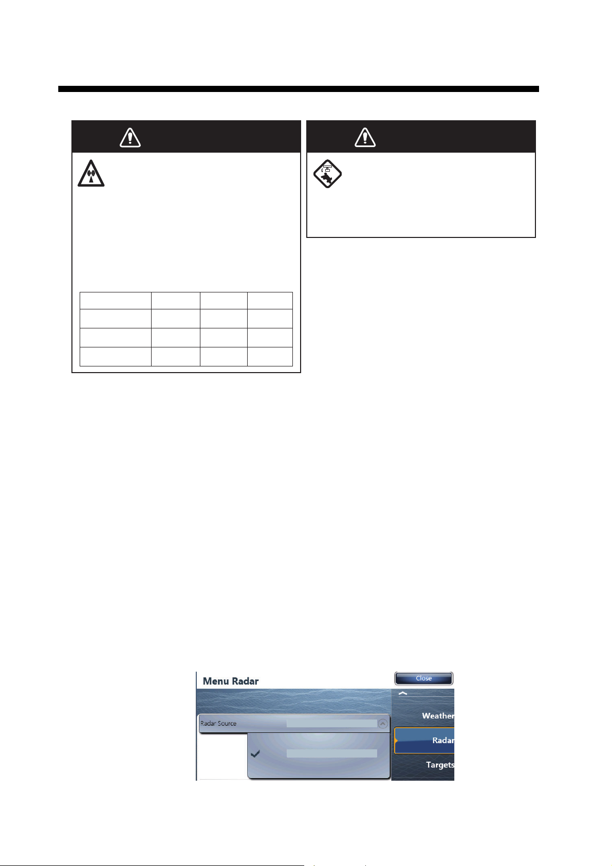
2. Select [Menu] on the menu icon bar to open the main menu.
3. Select [Radar].
4. Select [Radar Source] on the [Menu Radar] sub menus, then select the radar type
connected.
Note: If the antenna unit is connected but does not appear in the [Radar Source]
list, close the list and open it again. The name of the antenna unit should appear
with a check mark, as in the example below.
xxxxxxxx-xxxxxxxxxx
13
2. INITIAL SETUP
Title
Origin
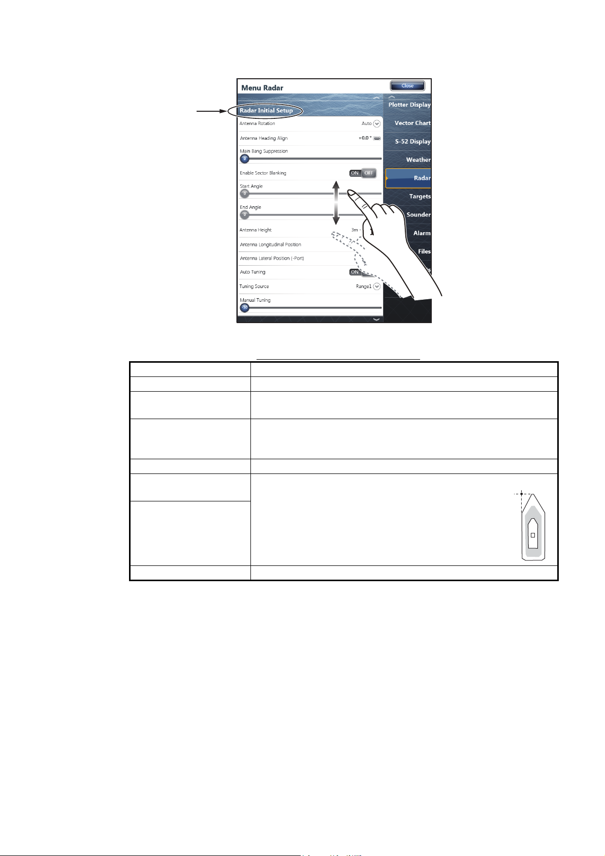
5. Drag the [Menu Radar] sub menus to find the menu item [Radar Initial Setup].
6. Set the items referring to the table shown below
Menu Radar (Radar Initial Setup)
Menu item Description
[Antenna Rotation] Select the speed of antenna rotation.
[Antenna Heading
Align]
[Main Bang Suppres-
sion]
[Antenna Height] Select the height of the antenna above the waterline.
[Antenna Longitudinal
Position]
[Antenna Lateral Posi-
tion (-Port)]
Others See Operator’ Manual for TZT9/14/BB.
See the topic of "How to align the antenna heading" on page 15.
If main bang appears at the screen center, slide the circle icon
so that the main bang disappears, while watching the radar
echo at the left-hand side of the display.
Enter the antenna positioning bow-stern (Longitudinal) and port-starboard (lateral) position from the
origin.
14
2. INITIAL SETUP
1
Range Range ring interval
Range indications
Zoom outZoom in
Pinch action
How to align the antenna heading
You have mounted the antenna unit facing straight ahead in the direction of the bow.
Therefore, a small but conspicuous target dead ahead visually should appear on the
heading line (zero degrees).
In practice, you will probably observe some small bearing error on the display because
of the difficulty in achieving accurate initial positioning of the antenna unit. The following adjustment will compensate for the error.
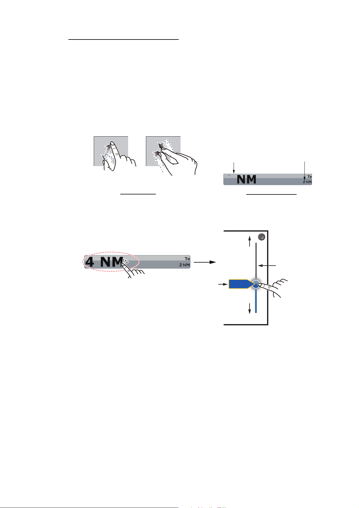
1. Select a range between 0.125 and 0.25 NM and set the mode to “head up“.
You can select a range by a pinch action. The range and range ring interval appear at the bottom left of the screen.
For TZTBB, you can also control the range in the operation as follows. Tap the
radar scale box at the bottom left-hand corner of the screen to display the slider
bar. Drag the circle icon to set the range scale.
Zoom in
Slider bar
Current
Tap the area circled in the dashed line to
display the slider bar.
Note: You can switch between transmit and
stand-by by tapping the right side of the
radar scale box.
range
4NM
Zoom out
Drag the circle
icon to set the
range scale.
2. Turn the vessel’s bow toward a target.
3. Press the Home key (or tap the Home icon), then select [Menu] icon, [Radar], and
[Antenna Heading Align] in that order to show the numeric software keyboard.
4. Key in the offset value so that the target is at the very top of the screen (setting
range: +/- 0° to 180°, +: clockwise direction, -: counterclockwise direction), then
tap [Save].
5. Confirm that the target echo is displayed at correct bearing on the screen.
15

2.2 Initial Setup for TZTL12F/TZTL15F
Origin
1. Tap the [Home] icon to show the home screen and display mode settings.
2. Tap [Radar] from the [Settings] menu.
3. Tap [Radar Source], then select the appropriate antenna unit.
Note: If the antenna unit is connected but does not appear in the [Radar Source]
list, close the list and open it again. The name of the antenna unit should appear
with a check mark, as in the example below.
xxxxxxxx-xxxxxxxxxx
4. Drag the [Radar] menu display the menu item [Radar Initial Setup], then tap
[Radar Initial Setup].
5. Referring to the tables below, set up the radar.
[Radar] menu - [Radar Initial Setup]
2. INITIAL SETUP
Menu item Description
[Antenna Rotation] Select the speed of antenna rotation.
[Antenna Heading Align] See "How to align the antenna heading" on page 17.
[Main Bang Suppression] If main bang appears at the screen center, slide the circle
icon so that the main bang disappears, while watching the
radar echo at the left-hand side of the display.
[Enable Sector Blanking] Up to two sectors may be selected for blanking (no trans[Enable Sector 2 Blanking]
mission). Select [ON] to enable this feature. Set the start
and end angles (0° to 359°).
[Radar] menu - [Antenna Position]
Menu item Description
[Longitudinal (from bow)] Referring to the figure on the right, enter the ra[Lateral (-Port)]
[Antenna Height] Select the height of the antenna above the waterline.
[Auto Tuning] Enable/disable auto tuning for the connected radar.
[Tuning Source] Select the range to tune.
[Manual Tuning] Manually tune the radar. Not available when [Auto Tuning]
[Radar Monitoring] Display various information regarding the connected ra-
[Radar Optimization] Automatically adjust magnetron output and tuning for the
[ARPA Advanced Settings] Do not change these settings.
[Set Hardware To Factory
Default]
[Reset Default Settings] Resets [Radar] menu settings to default.
dar antenna positioning bow-stern (Longitudinal) and port-starboard (Lateral) position from
the origin.
is enabled.
dar.
connected radar. Do not change these settings.
Resets the radar selected at [Radar Source] to factory default.
Origin
16

2. INITIAL SETUP
Zoom in
Zoom out
How to align the antenna heading
You have mounted the antenna unit facing straight ahead in the direction of the bow.
Therefore, a small but conspicuous target dead ahead visually should appear on the
heading line (zero degrees).
In practice, you will probably observe some small bearing error on the display because
of the difficulty in achieving accurate initial positioning of the antenna unit. The following adjustment will compensate for the error.
1. Set your radar with 0.125 and 0.25 NM range and the head up mode.
The range scale can be selected two ways, as shown below. The slider bar can
be shown or hidden with [Show Scale Slider] in the [Settings] - [Radar] menu.
Zoom in
Zoom in
Method 1: Pinch screen
Zoom out
Zoom out
NM
3
Method 2: Drag slider
(or tap bar or +, - icons)
2. Turn the vessel’s bow toward a target.
3. Tap the [Home] icon to show the home screen and display mode settings.
4. Tap [Radar] to show the [Radar] menu.
5. Drag the [Radar] menu to show the [RADAR INITIAL SETUP] menu.
6. Tap [Antenna Heading Align].
7. Key in the offset value so that the target is displayed at the very top of the screen
(setting range: +179.9° to -180°, +: clockwise direction, -: counterclockwise direc-
tion), then tap the icon.
8. Confirm that the target echo is displayed at correct bearing on the screen.
17

3. MAINTENANCE, TROUBLE
Do not apply paint, anti-corrosive
sealant or contact spray to coating or
plastic parts of the equipment.
Those items contain organic solvents
that can damage coating and plastic
parts, especially plastic connectors.
WARNING
NOTICE
Do not open the equipment.
Hazardous voltage which can
cause electrical shock exists
inside the equipment. Only
qualified personnel should work
inside the equipment.
Turn off the antenna unit
before servicing the unit.
Post a warning sign near the
switch indicating it should
not be turned on while the
antenna unit is being
serviced.
Prevent the potential risk of
being struck by the rotating
antenna.
A transmitting radar antenna
emits electromagnetic waves,
which can be harmful,
particularly the eyes.
Wear a safety belt and hard
hat when working on the
antenna unit.
Serious injury or death can
result if someone falls from the
radar antenna mast.
SHOOTING
Periodic checks and maintenance are important for proper operation of any electronic
system. This chapter contains maintenance and troubleshooting instructions to be followed to obtain optimum performance and the longest possible life of the equipment.
Before attempting any maintenance or troubleshooting procedure please review the
safety information below and at the front of this manual. If you cannot restore normal
operation after following the troubleshooting procedures, do not attempt to check inside any unit; there are no user serviceable parts inside. Contact your dealer to check
the equipment.
18

3. MAINTENANCE, TROUBLE SHOOTING
3.1 Maintenance
Regular maintenance is important for good performance. Check the points mentioned
below every 3 to 6 months to keep the antenna unit in good working order.
Check point Action Remedy, remarks
Cable Check that all cables are firmly
connected and are not damaged.
Exposed
bolts and nuts
Radiator Dust, dirt and salt deposits on
Ground connection
Check that bolts and nuts are
corroded and are securely fastened.
the radiator cause signal attenuation, resulting in loss of sensitivity.
Check for tight connection and
rust.
• Connect a cable if it has loosened.
• Replace damaged cables.
• Replace corroded bolts.
• Tighten loosened bolts.
• Coat new bolts with marine sealant.
• Wipe radiator with a freshwatermoistened cloth.
• The radiator is made of fiberglass
reinforced plastic. Therefore, do not
used gasoline, benzene and the like
to clean the radiator.
• If the radiator is iced, use a wooden
or plastic headed hammer to remove the ice. DO NOT use a steel
hammer.
• Fasten if loosened.
• Remove rust if present.
3.2 Troubleshooting
The table below provides simple troubleshooting procedures to restore normal operation. If you cannot restore normal operation, contact your dealer for advice.
Problem Remedy
The multi function display cannot control the radar.
Marks and characters appear,
but echoes do not appear.
Picture is not updated or the
picture freezes.
You tuned the receiver or increase the gain, but radar
echoes are too week.
You changed the range, but the
radar picture does not change.
Poor discrimination in range. • Adjust the sea control.
Range rings are not displayed. • Check if the range rings is turned on in the menu.
You set the radar in the transmit
state. The "TX screen" appears
momentarily, but the radar soon
goes into stand-by.
• Check that all cables are tightly fastened.
• Check if the radar source setting is correct.
• Check if the fuse of the power/LAN cable has
blown.
• Check that the power supply is compatible with the
voltage rating of the antenna unit (24 VDC).
• Check that the antenna cable is tightly fastened.
• Check the cables for damage.
• Check that all cables are tightly fastened.
• Check the cables for damage.
• If the picture has frozen, reboot the multi function
display.
• The life span of the magnetron is over. Contact your
dealer to check the magnetron.
• Try to change the range again.
• Reboot the multi function display.
• The overload protection has activated. To restore
normal operation, turn off all equipment in the network. Wait a few seconds then turn on all the equipment.
19

3.3 Replacement of Fuse
WARNINGWARNING
Use the proper fuse.
Use of a wrong fuse can cause
fire or damage the equipment.
Fuse holder
How to replace the fuse
Open the fuse holder cover and replace
the fuse. Then close the cover.
Power/LAN cable
The 5 A fuse (Type: FRU-2P5S-FU-5A-B, Code No.: 000-168-869-10) in the fuse
holder on the power/LAN cable protects the antenna unit from overcurrent and equipment fault. If you cannot turn on the power, check the fuse to see if it has blown. If the
fuse has blown, find the reason before you replace the fuse. If the fuse blows again
after the replacement, contact your dealer for advice.
3. MAINTENANCE, TROUBLE SHOOTING
3.4 Life of Parts
Magnetron
When a magnetron reaches the end of its life, targets do not appear on the display. If
long-range performance appears to have declined, contact your dealer about replacement of the magnetron.
Name Type Code No. Approx. Life
Magnetron MAF1422B 000-158-788-12 5,000 hours
Antenna Motor
When an antenna motor reaches the end of its life, the antenna’s rotation may stop or
abnormal noise sounds from the antenna unit. If such symptom occurs, contact your
dealer about replacement of the antenna motor.
Name Type Code No. Approx. Life
Antenna Motor DJ8G-23B48H TBD 10,000 hours
20

FURUNO
DRS6A X-Class
SPECIFICATIONS OF RADAR SENSOR
DRS6A X-Class
1 ANTENNA UNIT
1.1 Antenna type Slotted waveguide array
1.2 Antenna length 3.4 ft (XN10A), 4 ft (XN12A), 6 ft (XN13A)
1.3 Horizontal beam width 2.3° (XN10A), 1.9° (XN12A), 1.4° (XN13A)
1.4 Vertical beam width 22°
1.5 Gain 27.5 dBi (XN10A), 28.5 dBi (XN12A), 30 dBi (XN13A)
1.6 Sidelobe attenuation
XN10A -20 dB (within ±20°), -28 dB (±20° or more)
XN12A -24 dB (within ±20°), -30 dB (±20° or more)
XN13A -28 dB (within ±10°), -35 dB (±10° or more)
1.7 Rotation 24/36/48 rpm range coupled or 24 rpm fixed
2 RADAR FUNCTION
2.1 Tx frequency 9410 ±30 MHz
2.2 Output power 6 kW nominal
2.3 Duplexer Ferrite circulator with diode limiter
2.4 Intermediate frequency 60 MHz
2.5 Range, Pulse length and Pulse Repetition Rate (PRR)
Range (NM)
0.0625 to 0.75 0.08 3000
1 to 1.5 0.15 3000
2 0.3 1500
3 to 4 0.5 1000
6 to 8 0.8 600
12 to 120 1.2 600
2.6 Maximum range 120 NM
2.7 Minimum range 25 m
2.8 Range resolution 20 m
2.9 Range accuracy 1% of range in use or minimum VRM, whichever is the greater
2.10 Bearing resolution 2.3° (XN10A), 1.9° (XN12A), 1.4° (XN13A)
2.11 Bearing accuracy ±1°
2.12 Warm-up time 90 s approx.
2.13 Target tracking (TT) Auto or manual acquisition: 30 targets in 16 NM
Past position: 5/10 pts on all activated targets
Vector time: Off, 1 to 60 min.
Pulse length (s)
3 INTERFACE
LAN: 1 port, Ethernet, 100Base-TX
4 POWER SUPPLY
24 VDC: 3.7 A
PRR (Hz. approx.)
SP - 1 E3646S01A
150624

FURUNO
5 ENVIRONMENTAL CONDITIONS
5.1 Ambient temperature -25°C to +55°C (storage: -30°C to +70°C)
5.2 Relative humidity 95% or less at +40°C
5.3 Degree of protection IP56
5.4 Vibration IEC 60945 Ed.4
6 UNIT COLOR
N9.5
DRS6A X-Class
SP - 2 E3646S01A
150624

D-1
30/Jun/2015 H.MAKI

DRS6A X-CLASS
S-1
レーダーセンサー
相互結線図
RADAR SENSOR
INTERCONNECTION DIAGRAM
43
*1
IV-2sq.
TITLE
T.YAMASAKI
名称
H.MAKI
NAME
REF.No.
kg
25/Jun/2015
C3646-C01- A
25/Jun/2015
CHECKED
DRAWN
APPROVED
DWG.No.
SCALE MASS
空中線部
ANTENNA UNIT
RSB-134
0.5m
7
2
5A
RED
BLU
アカ
アオ
FRU-2P5S-FF-10M/20M/30M,10/20/30m
FRU-2P5S-FF-15M,15m,φ9.7
(+)
(-)
RJ45
ジョイントボックス
RJ45LAN
8
*2
JUNCTION BOX
TL-CAT-012
8
8
ORまたは
イーサネットハブ
24VDC
マルチファンクションディスプレイ
8
*2
HUB-101
ETHERNET HUB
TZT9/14/BB,TZTL12F/15F
MULTI FUNCTION DISPLAY
ネットワーク機器
8
(+)
J1VH2P-MVVS0.75x2C
1
WHT
シロ
NETWORK EQUIPMENT
(-)
2
BLK
クロ
1
MULTI FUNCTION DISPLAY
マルチファンクション
ディスプレイ
TZT9/14/BB
TZTL12F/15F
A
12-24VDC
B
注記
*1)造船所手配。
*2)オプション。
NOTE
*1: SHIPYARD SUPPLY.
*2: OPTION.
C

IME-36460-Z2
Z2 JUL. 22, 2015
 Loading...