

Furuno USA 9ZWRTR1119 User Manual
2. INITIAL SETUP
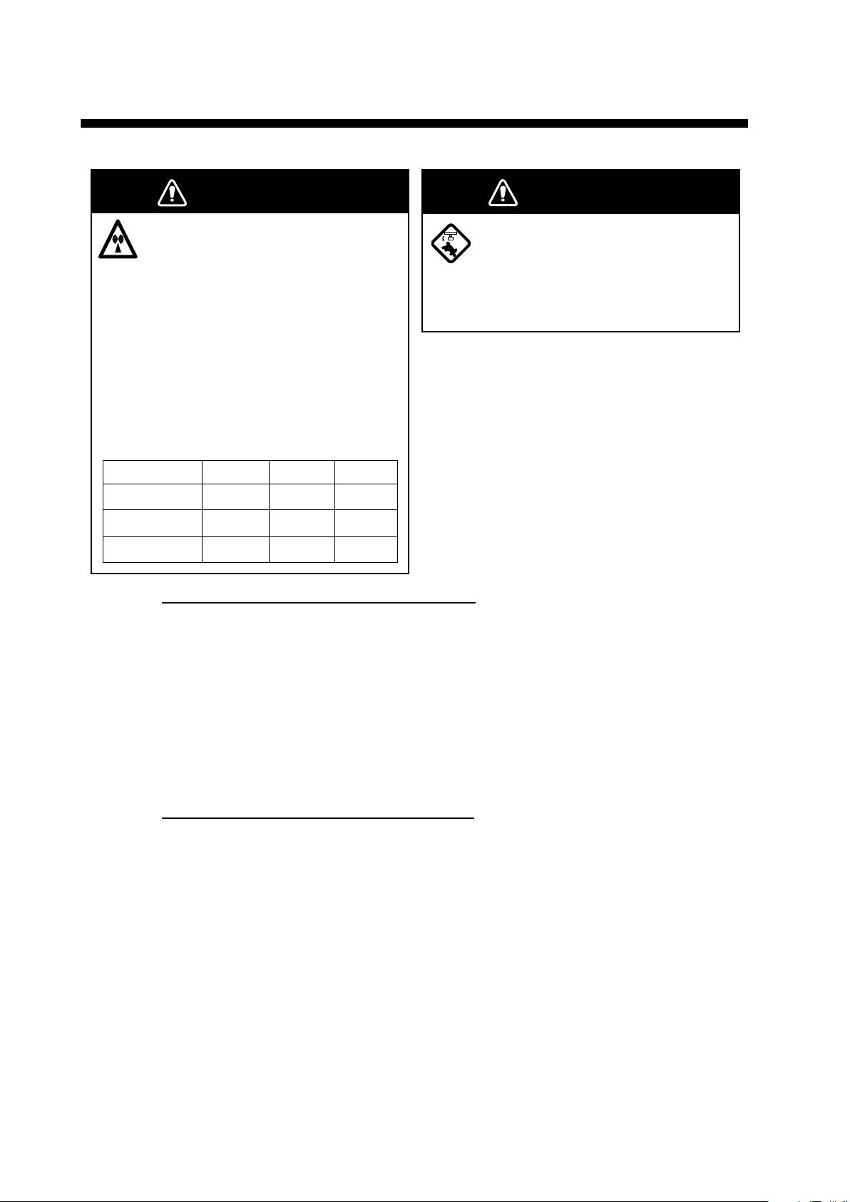
WARNING
The radar antenna emits
electromagnetic radio frequency
(RF) energy which can be
harmful, particularly to your eyes.
Never look directly into the
antenna aperture from a close
distance while the radar is in
operation or expose yourself to
the transmitting antenna at a
close distance.
Distances at which RF radiation
levels of 100, 50 and 10 W/m
are given in the table below.
Radiator
XN10A
XN12A
XN13A
100 W/m250 W/m210 W/m
N/A
N/A 0.6 mN/A
N/A 0.4 mN/A
Vessels equipped with SC-50/60/110/120
2
exist
0.7 mN/A
2
WARNING
Before turning on the radar, be sure
no one is near the antenna.
Prevent the potential risk of being
struck by the rotating antenna, which
can result in serious injury or death.
For the comfort use of target analyzer function, an appropriate time need to be set in
the [SMOOTH S/C] menu. When the time set in this menu is too long, the landmass
can be judged as approaching target and displayed in red while accelerating, decelerating or turning. If this symptom occur too often, shorten the time in [SMOOTH S/C]
menu.
Note: Unstableness of COG and SOG can be larger when the [SMOOTH S/C] time
become shorter. Set the time avoiding the influence to other navigational equipment,
such as GPS plotter and autopilot.
Installation with Multi Function Displays
This radar series is compatible with the FURUNO Multi Function Displays and software version combinations shown below. The combination with other models may not
operate properly.
• TZT9, TZT14 and TZTBB: Version 5.01 or later
TZTL12F and TZTL15F: Version 5.01 or later
Turn on the antenna unit and FURUNO Multi Function Display. Initial setup for this antenna must be done on the FURUNO Multi Function Display.
15
2.1 Initial Setup for TZT9/TZT14/TZTBB
T
T
1. Press the Home key (or tap the Home icon).
2. Select [Menu] on the menu icon bar to open the main menu.
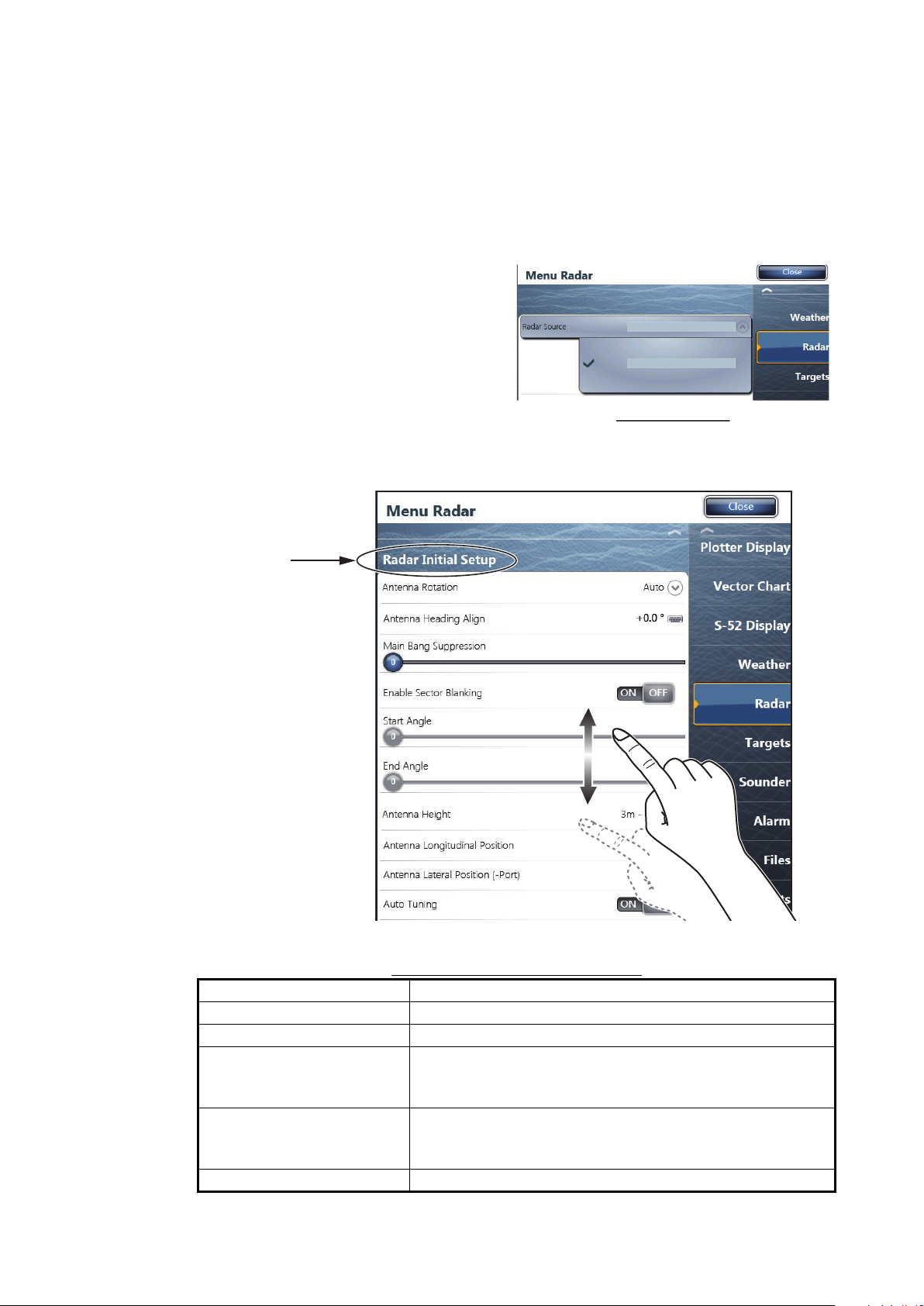
3. Select [Radar].
4. Select [Radar Source] on the [Menu Radar] sub menus, then select the radar type
connected.
Note: If the antenna unit is connected but does not appear in the [Radar Source] list, close the list and
open it again. The name of the antenna unit should appear with a
check mark, as in the example to
the right.
5. Drag the [Menu Radar] sub menus
to find the menu item [Radar Initial
Setup].
RDxxxxxx - DRS6A-NX
RDxxxxxx - DRS6A-NX
Display example
2. INITIAL SETUP
Title
6. Set the items referring to the table shown below
Menu Radar (Radar Initial Setup)
Menu item Description
[Antenna Rotation] Select the antenna rotation speed.
[Antenna Heading Align] See "How to align the antenna heading" on page 17.
[Main Bang Suppression] If main bang appears at the screen center, slide the circle
icon, while watching the radar echo on the left-side of the
display, until the main bang disappears.
[Enable Sector Blanking]/
[Enable Sector Blanking2]
Up to two sectors may be selected for blanking (no transmission). Select [ON] to enable this feature. Set the start
and end angles (0° to 359°).
[Antenna Height] Select the height of the antenna above the waterline.
16

2. INITIAL SETUP
Origin
A
[Antenna Length] Selects the length of the antenna.
[Antenna Longitudinal Position]
[Antenna Lateral Position
(-Port)]
[Radar Monitoring] Display various information regarding the connected ra-
[ARPA Advanced Settings] For service technician only. Do not change these settings.
[TX Channel] Select [1],[2] or [3], the channel where the interference is
[Target Analyzer Mode] You can emphasize rain clutter or target echoes when the
[Auto Acquire by Doppler] When selecting [ON], approaching targets within 3 NM
[Hardware Factory Default] Resets the radar selected at [Radar Source] to factory de-
[Reset Default Settings] Resets [Radar] menu settings to default.
Menu item Description
RezBoost function reflects the selection of this menu item.
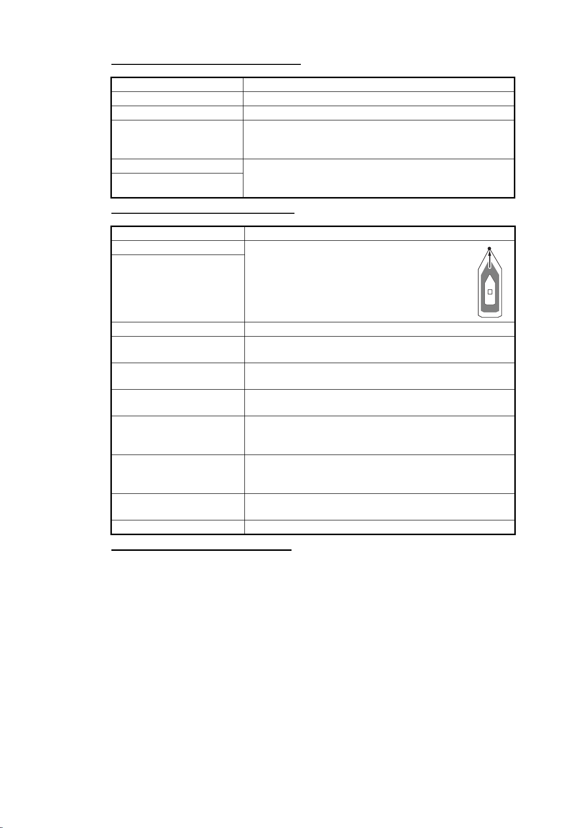
Referring to the figure on the right, enter the ra-
dar antenna positioning bow-stern (Longitudinal) and port-starboard (Lateral) position from
the origin.
dar.
This menu item is available when setting the radar in
transmit.
smallest.
target analyzer is active. Select [Rain] or [Target] as appropriate.
from own ship are automatically acquired by the Doppler
calculated from the radar echo.
fault.
Origin
How to align the antenna heading
You have mounted the antenna unit facing straight ahead in the direction of the bow.
Therefore, a small but conspicuous target dead ahead visually should appear on the
heading line (zero degrees).
You may observe a minor bearing error on the display. This is due to the difficulty in
orienting the radar accurately. The following adjustment will compensate for the error.
Correct bearing of target
(relative to heading)
a
ntenna oriented
to port
Target
000
010
350
340
330
320
310
300
290
280
270
260
250
240
230
220
210
200
020
030
150
160
190
170
180
Picture appears with
clockwise deviation.
040
050
130
140
a
060
070
080
090
Displayed
100
position
110
120
of target
Displayed position of target
Ta rg e t
b
Antenna oriented
to starboard
320
310
300
290
280
270
260
250
240
230
220
Picture appears with
counterclockwise deviation.
b
000
010
350
340
330
210
200
020
030
040
050
060
070
080
090
Correct
100
110
bearing of
120
target
130
140
150
160
190
170
180
(relative to
heading)
17
2. INITIAL SETUP
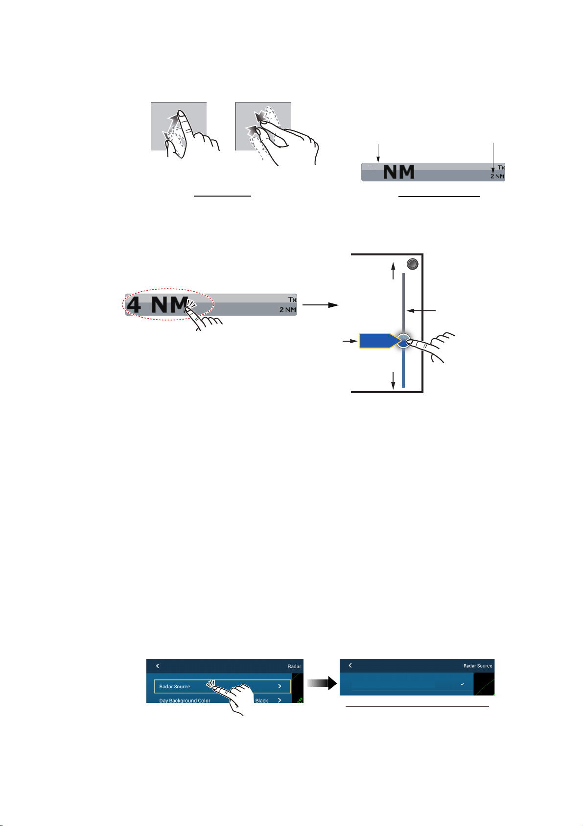
1. Select a range between 0.125 and 0.25 NM and set the mode to “head up“.
You can select a range by a pinch action. The range and range ring interval appear at the bottom left of the screen.
Range Range ring interval
Zoom outZoom in
Pinch action
1
Range indications
For TZTBB, you can also control the range in the operation as follows. Tap the
radar scale box at the bottom left-hand corner of the screen to display the slider
bar. Drag the circle icon to set the range scale.
Zoom in
Slider bar
Current
Tap the area circled in the dashed line to
display the slider bar.
Note: You can switch between transmit and
stand-by by tapping the right side of the
radar scale box.
range
4NM
Zoom out
Drag the circle icon to
set the range scale.
2. Turn the vessel’s bow toward a target.
3. Press the Home key (or tap the Home icon), then select [Menu] icon, [Radar], and
[Antenna Heading Align] in that order to show the numeric software keyboard.
4. Key in the offset value so that the target is at the very top of the screen (setting
range: +/- 0° to 180°, +: clockwise direction, -: counterclockwise direction), then
tap [Save].
5. Confirm that the target echo is displayed at correct bearing on the screen.
2.2 Initial Setup for TZTL12F/TZTL15F
1. Tap the [Home] icon to show the home screen and display mode settings.
2. Tap [Radar] from the [Settings] menu.
3. Tap [Radar Source], then select the appropriate antenna unit.
Note: If the antenna unit is connected but does not appear in the [Radar Source]
list, close the list and open it again. The name of the antenna unit should appear
with a check mark, as in the example below.
RDxxxxxx - DRS6A-NXT
Display example for DRS6A-NXT
4. Drag the [Radar] menu display the menu item [Radar Initial Setup], then tap
[Radar Initial Setup].
5. Referring to the tables below, set up the radar.
18
2. INITIAL SETUP
Origin
[Radar] menu - [Radar Initial Setup]
[Antenna Rotation] Select the antenna rotation speed.
[Antenna Heading Align] See "How to align the antenna heading" on page 19.
[Main Bang Suppression] If main bang appears at the screen center, slide the circle
[Enable Sector Blanking] Up to two sectors may be selected for blanking (no trans[Enable Sector 2 Blanking]
[Radar] menu - [Antenna Position]
[Longitudinal (from bow)] Referring to the figure on the right, enter the ra[Lateral (-Port)]
Menu item Description
icon so that the main bang disappears, while watching the
radar echo at the left-hand side of the display.
mission). Select [ON] to enable this feature. Set the start
and end angles (0° to 359°).
Menu item Description
dar antenna positioning bow-stern (Longitudinal) and port-starboard (Lateral) position from
the origin.
Origin
[Antenna Height] Selects the height of the antenna above the waterline.
[Antenna Length] Selects the length of the antenna.
RezBoost function reflects the selection of this menu item.
[Radar Monitoring] Display various information regarding the connected ra-
dar.
[TX Channel] Select [1], [2] or [3], the channel where the interference is
smallest.
[Target Analyzer Mode] You can emphasize rain clutter or target echoes when the
target analyzer is active. Select [Rain] or [Target] as appropriate.
[Auto acquire by Doppler] When selecting [ON], approaching targets within 3 NM
from own ship are automatically acquired by the Doppler
calculated from the radar echo.
[Set Hardware To Factory
Default]
[Reset Default Settings] Resets [Radar] menu settings to default.
Resets the radar selected at [Radar Source] to factory default.
How to align the antenna heading
You have mounted the antenna unit facing straight ahead in the direction of the bow.
Therefore, a small but conspicuous target dead ahead visually should appear on the
heading line (zero degrees).
You may observe a minor bearing error on the display. This is due to the difficulty in
orienting the radar accurately. The following adjustment will compensate for the error.
19
2. INITIAL SETUP
A
Zoom in
Zoom out
Correct bearing of target
(relative to heading)
a
Target
ntenna oriented
to port
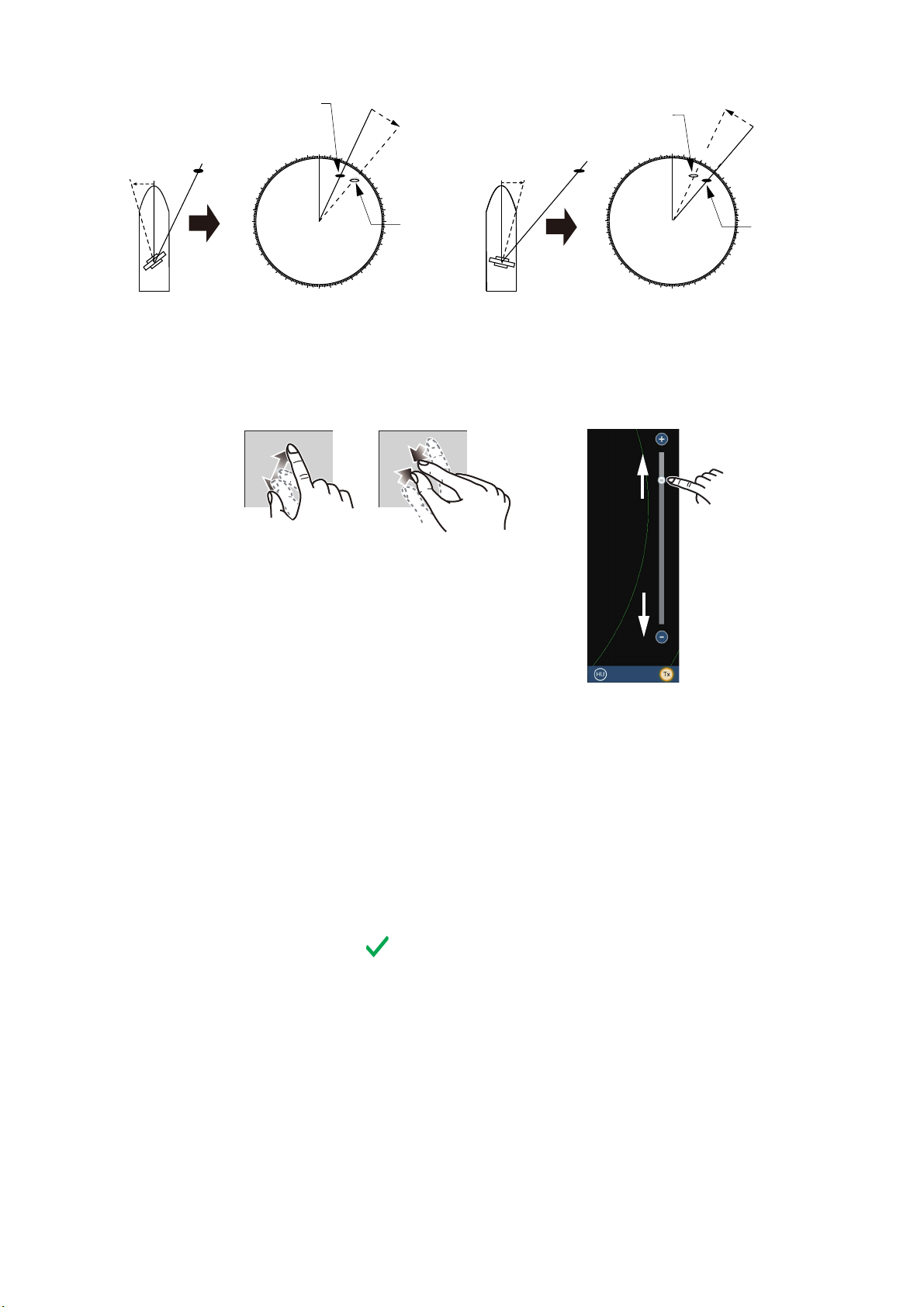
1. Set your radar with 0.125 and 0.25 NM range and the head up mode.
The range scale can be selected two ways, as shown below. The slider bar can
be shown or hidden with [Show Scale Slider] in the [Settings] - [Radar] menu.
000
010
350
340
330
320
310
300
290
280
270
260
250
240
230
220
210
200
020
030
150
160
190
170
180
Picture appears with
clockwise deviation.
Zoom in
040
050
130
140
a
060
070
080
090
Displayed
100
position
110
120
of target
Zoom out
Displayed position of target
Target
b
Antenna oriented
to starboard
320
310
300
290
280
270
260
250
240
230
220
Picture appears with
counterclockwise deviation.
Zoom in
b
000
010
350
340
330
210
200
020
030
040
050
060
070
080
090
Correct
100
110
bearing of
120
target
130
140
150
160
190
170
180
(relative to
heading)
Method 1: Pinch screen
Zoom out
NM
3
Method 2: Drag slider
(or tap bar or +, - icons)
2. Turn the vessel’s bow toward a target.
3. Tap the [Home] icon to show the home screen and display mode settings.
4. Tap [Radar] to show the [Radar] menu.
5. Drag the [Radar] menu to show the [RADAR INITIAL SETUP] menu.
6. Tap [Antenna Heading Align].
7. Key in the offset value so that the target is displayed at the very top of the screen
(setting range: +179.9° to -180°, +: clockwise direction, -: counterclockwise direc-
tion), then tap the icon.
8. Confirm that the target echo is displayed at correct bearing on the screen.
20
 Loading...