

Furuno USA 9ZWRTR110 operators manual

OPERATOR'S MANUAL
MARINE RADAR
FAR-1467DS
MODEL
FAR-1467DS-BB
www.furuno.com

9-52 Ashihara-cho,
*
00017580410
**00017580410
*
*
00017580410
**00017580410
*
Nishinomiya, 662-8580, JAPAN
The paper used in this manual
is elemental chlorine free.
・FURUNO Authorized Distributor/Dealer
All rights reserved.
Pub. No. OME-36120-Z
(DAMI ) FAR-1467DS/1467DS-BB
Printed in Japan
A : 0000
Z : MAR . 30, 2012
* 0 0 0 1 7 5 8 0 4 1 0 *

IMPORTANT NOTICES
Cd
General
• This manual has been authored with simplified grammar, to meet the needs of
international users.
• The operator of this equipment must read and follow the descriptions in this manual.
Wrong operation or maintenance can cancel the warranty or cause injury.
• Do not copy any part of this manual without written permission from FURUNO.
• If this manual is lost or worn, contact your dealer about replacement.
• The contents of this manual and equipment specifications can change without notice.
• The example screens (or illustrations) shown in this manual can be different from the
screens you see on your display. The screens you see depend on your system
configuration and equipment settings.
• Save this manual for future reference.
• Any modification of the equipment (including software) by persons not authorized by
FURUNO will cancel the warranty.
• All brand and product names are trademarks, registered trademarks or service marks of
their respective holders.
How to discard this product
Discard this product according to local regulations for the disposal of industrial waste. For
disposal in the USA, see the homepage of the Electronics Industries Alliance
(http://www.eiae.org/) for the correct method of disposal.
How to discard a used battery
Some FURUNO products have a battery(ies). To see if your product has a battery, see the
chapter on Maintenance. Follow the instructions below if a battery is used. Tape the + and terminals of battery before disposal to prevent fire, heat generation caused by short circuit.
In the European Union
The crossed-out trash can symbol indicates that all types of
batteries must not be discarded in standard trash, or at a trash
site. Take the used batteries to a battery collection site according
to your national legislation and the Batteries Directive
2006/66/EU.
In the USA
The Mobius loop symbol (three chasing arrows) indicates that
Ni-Cd and lead-acid rechargeable batteries must be recycled. Take
the used batteries to a battery collection site according to local
laws.
Ni-Cd Pb
In the other countries
There are no international standards for the battery recycle symbol. The number of symbols
can increase when the other countries make their own recycling symbols in the future.
i
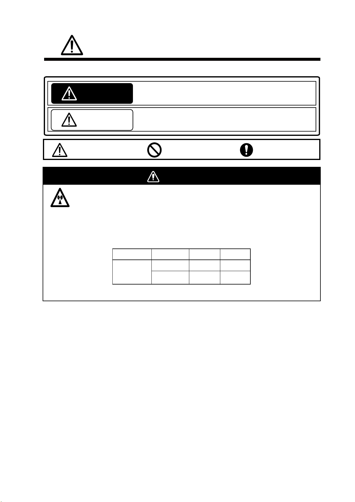
SAFETY INSTRUCTIONS
The operator must read the safety instructions before attempting to operate the equipment.
WARNING
CAUTION
Warning, Caution
Indicates a potentially hazardous situation which, if not avoided,
could result in death or serious injury.
Indicates a potentially hazardous situation which, if not avoided,
could result in minor or moderate injury.
Prohibitive Action
Mandatory Action
WARNING
Radio Frequency Radiation Hazard
The radar antenna emits electromagnetic radio frequency (RF) energy that can be harmful,
particularly to your eyes. Never look directly into the antenna aperture from a close distance
while the radar is in operation or expose yourself to the transmitting antenna at a close
distance. Distances at which RF radiation level of 100, 50 and 10 W/m
below.
Model Antenna
100W/m
2
10W/m
2
are given in the table
2
FAR-1467DS
SN24AF
SN30AF
0.6 m
0.5 m
8.5 m
7.7 m
ii
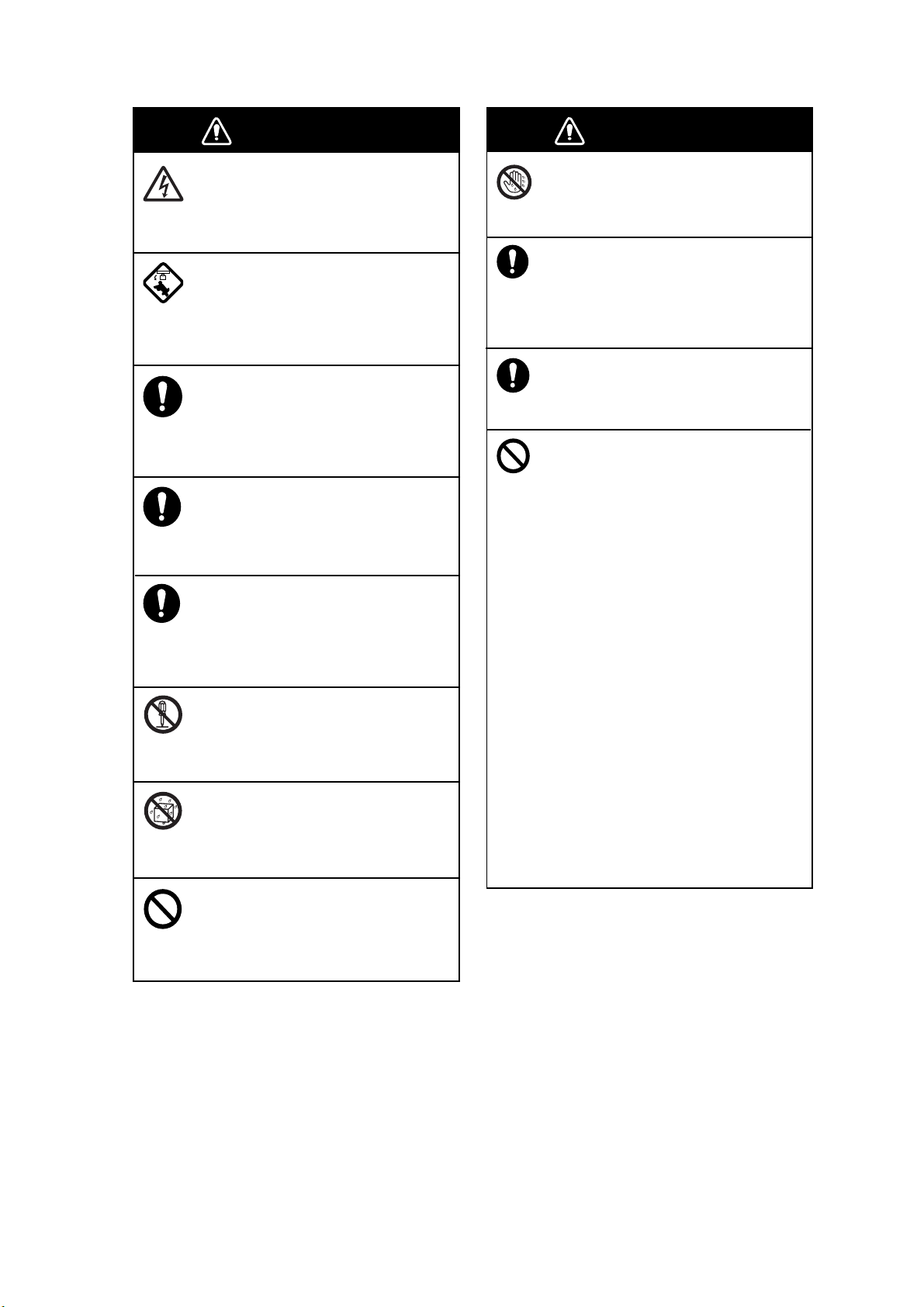
WARNING
WARNING
Do not open the equipment.
The equipment uses high voltage that
can cause electrical shock. Refer any
repair work to a qualified technician.
Before turning on the radar, be sure
no one is near the antenna.
Prevent the potential risk of being
struck by the rotating antenna, which
can result in serious injury or death.
If water leaks into the equipment or
something is dropped into the
equipment, immediately turn off the
power at the switchboard.
Fire or electrical shock can result.
If the equipment is giving off smoke
or fire, immediately turn off the
power at the switchboard.
Fire or electrical shock can result.
If you feel the equipment is acting
abnormally or giving off strange
noises, immediately turn off the
power at the switchboard and
contact a FURUNO service technician.
Do not disassemble or modify the
equipment.
Fire, electrical shock or serious injury
can result.
Make sure no rain or water splash
leaks into the equipment.
Fire or electrical shock can result if
water leaks into the equipment.
WARNING
Do not operate the equipment with
wet hands.
Electrical shock can result.
Keep objects away from the open-ntype antenna unit, so as not to
impede rotation of the antenna.
Fire, electrical shock or serious injury
can result.
Use the proper fuse.
Use of the wrong fuse can cause fire or
electrical shock.
Do not depend on one navigation
device for the navigation of the ship.
The navigator must check all aids
available to confirm position.
- The TT automatically tracks an
automatically or manually acquired
radar target and calculates its course
and speed, indicating them with a
vector. Since the data generated by
the TT depends on the selected radar
targets, the radar must be optimally
tuned for use with the TT, to ensure
required targets will not be lost or
unnecessary targets like sea returns
and noise will not be acquired and
tracked.
- A target is not always a landmass,
reef, ship, but can also be returns
from the sea surface and from clutter
As the level of clutter changes with
the environment, the operator must
correctly adjust the sea and rain
clutter controls and the gain control so
that the target echoes do not disappear from the radar screen.
Do not place liquid-filled containers
on or near the equipment.
Fire or electrical shock can result if a
liquid spills into the equipment.
iii

TABLE OF CONTECTS
FOREWORD ..................................................................................................................vii
SYSTEM CONFIGURATION .........................................................................................viii
1. BASIC OPERATION ...................................................................................................1
1.1 Using keys and knobs .............................................................................................................1
1.2 Turning ON/OFF the Power, Transmission..............................................................................3
1.3 Examples of Screen Display ...................................................................................................4
1.4 Operating from boxes on the screen.......................................................................................6
1.5 Brilliance and Color Scheme...................................................................................................7
1.6 Tuning .....................................................................................................................................8
1.7 Display Modes ........................................................................................................................8
1.8 Selecting range ..................................................................................................................... 11
1.9 Adjusting Gain....................................................................................................................... 11
1.10 Rejecting Sea Clutter ...........................................................................................................12
1.11 Rejecting Precipitation Clutter ...............................................................................................12
1.12 Automatic rejection of sea clutter and precipitation clutter ....................................................13
1.13 Deleting heading line temporarily ..........................................................................................13
1.14 Cursor position......................................................................................................................14
1.15 Measuring range to target.....................................................................................................15
1.16 Measuring bearing of target ..................................................................................................16
1.17Measuring Range and Bearing between Two Targets............................................................18
1.18 Selecting Transmission Pulse Length ...................................................................................18
1.19Off-Centering the Display.......................................................................................................19
1.20 Rejecting Interference...........................................................................................................19
1.21 Echo Stretch..........................................................................................................................19
1.22 Signal Processing Function...................................................................................................20
1.23 Echo Trail Function ............................................................................................................... 21
1.24 Watch Alarm..........................................................................................................................22
1.25 Parallel Cursor ......................................................................................................................25
1.26 Setting Images ......................................................................................................................26
1.27 Function Keys .............................................................................................................
1.28 Alarm.....................................................................................................................................28
1.29 Reference Position................................................................................................................29
1.30 Interswitch.............................................................................................................................31
..........28
2. RADAR OPERATION USING MENU........................................................................33
2.1 Menu Operation ....................................................................................................................33
2.2 Echo Display Area.................................................................................................................34
2.3 Registering Function Keys ....................................................................................................35
2.4 Drop Mark .............................................................................................................................40
2.5 Watch Alarm..........................................................................................................................42
2.6 Zoom.....................................................................................................................................43
2.7 Anchor Watch Alarm ............................................................................................................. 45
2.8 Priority Order of Various Alarms ............................................................................................46
2.9 Color Scheme .......................................................................................................................47
2.10 Menus of Each Function .......................................................................................................49
2.11 Menu Items ...........................................................................................................................60
3. TARGET TRACKING (TT) ........................................................................................66
iv

3.1 Usage Precautions................................................................................................................66
3.2 Turning TT ON/OFF ..............................................................................................................67
3.3 Ship Speed Input...................................................................................................................67
3.4 Target Acquisition and Tracking ............................................................................................67
3.5 Terminating Tracking.............................................................................................................72
3.6 Lost Target ............................................................................................................................72
3.7 Displaying Target Data ..........................................................................................................74
3.8 Changing Shape and Color of TT Mark.................................................................................77
3.9 Zoom Target..........................................................................................................................79
3.10 Displaying Vector ..................................................................................................................80
3.11 Displaying Track....................................................................................................................82
3.12 Guard Zone Alarm.................................................................................................................83
3.13 Setting Collision Alarm (CPA/TCPA alarm)............................................................................84
3.14 TT Ship Speed Alarm ............................................................................................................85
3.15 Test Steering (Steering simulation)........................................................................................85
4. AIS OPERATION ......................................................................................................90
4.1 Turning ON/OFF AIS Display ................................................................................................ 90
4.2 Activated Target ....................................................................................................................92
4.3 Inactivating targets................................................................................................................93
4.4 Displaying AIS Target Data.................................................................................................... 94
4.5 Filtering AIS display...............................................................................................................96
4.6 AIS Symbol Attributes ........................................................................................................... 97
4.7 Displaying Vector ..................................................................................................................99
4.8 Displaying Past Position......................................................................................................100
4.9 Lost Target ..........................................................................................................................101
4.10 Collision Alarm (CPA/TCPA)................................................................................................103
4.11 Activating Targets ................................................................................................................103
4.12 Turning Direction.................................................................................................................105
4.13 Identification of TT and AIS .................................................................................................105
4.14 Navigation Data...................................................................................................................107
4.15 Static Data...........................................................................................................................108
4.16 Messages............................................................................................................................109
5. VIDEO PLOTTER OPERATION.............................................................................. 112
5.1 Outline................................................................................................................................. 112
5.2 Mark/Destination/Line ......................................................................................................... 112
5.3 Origin Mark .........................................................................................................................122
5.4 Chart (Coastline data) .........................................................................................................125
5.5 Track...................................................................................................................................134
5.6 Route ..................................................................................................................................137
5.7 Waypoint .............................................................................................................................140
5.8 Plotter related alarms ..........................................................................................................144
5.9 Recording/Replaying Data ..................................................................................................145
6. MAINTENANCE AND TROUBLESHOOTING ........................................................149
6.1 Periodic Maintenance Schedule..........................................................................................150
6.2 Parts requiring exchanges and recommended schedule ....................................................151
6.3 Replacing Fuse ...................................................................................................................152
6.4 Replacing Battery................................................................................................................152
6.5 Trackball Maintenance ........................................................................................................153
6.6 Simple Troubleshooting.......................................................................................................154
6.7 Troubleshooting by Qualified Technician............................................................................. 155
6.8 Diagnostic ...........................................................................................................................157
6.9 TT Performance Test...........................................................................................................158
v

6.10 Displaying Sentences..........................................................................................................159
APPENDIX ALART LIST ...........................................................................................AP-1
vi

FOREWORD
Congratulations on your purchase of our products. Since 1948, FURUNO Electric Company has
enjoyed an enviable reputation for performance, quality and reliability of our marine electronics
equipment from users around the world. Your radar is designed and constructed to meet the
rigorous demands of the marine environment. Please carefully read and follow the recommended
procedures for operation and maintenance of the machine to fully perform its intended functions.
Features
The FAR-1467DS consists of an antenna unit, processor unit, monitor unit and control unit.
Following are the main features.
• Type 15/19 High brilliance color LCD.
• One USB port in the control unit for data backup.
• Ability to memorize optimum image settings and switch instantaneously to detect far distance,
birds and float receptions, etc.
• Equipped with the true view function to smoothly turn radar echoes according to own ship’s
turns. (Head-up, Cursor Gyro, Stern Up modes only)
• Various alarm functions (Guard, Watch, Anchor watch, Guard zone, Arrival to destination, XTE,
etc.)
• TT* (Track target) function to watch other ships’ movement (*: equivalent to the conventional
ARPA function)
• Ability to display AIS data by connecting to the vessel automatic identification system (AIS
transponder).
• Ability to display chart layers (includes vector charts throughout Japan)
• Large capacity memory - Mark: max.20,000 points, Line (include routes): max.5,000 points,
Destination: max.100 points, Own ship’s track: max.20,000 points, Other ships’ track: max.
200,000 points
vii
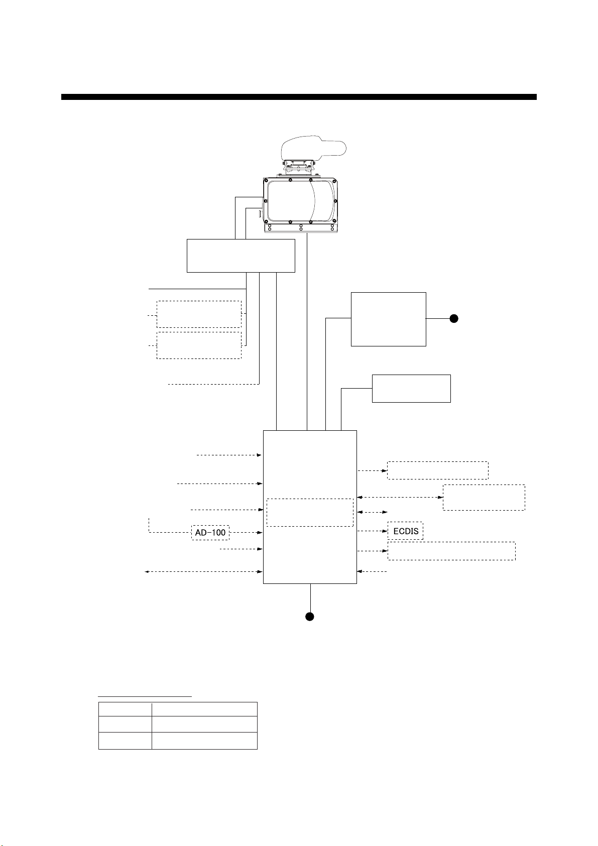
SYSTEM CONFIGURATION
ANTENNA UNIT
RADIATOR
SN24AF
SN30AF
SN36AF
CHASSIS
RSB-132
POWER SUPPLY UNIT
PSU-006
200 V AC , 3φ, 50 Hz
220 V AC , 3φ, 60 Hz
110 V AC , 3φ, 60 Hz
220 V AC , 3φ, 60 Hz
100-115V/220-230 V AC ,
1φ, 50/60 Hz
GPS Navigator
Speed Log
Gyrocompass
NMEA reading signal
AIS
(For antenna motor)
TRANSFORMER
RU-5693
TRANSFORMER
RU-6522
(For high voltage)
PROCESSOR UNIT
PRU-021
GIRO CONVERTER
GC-100
MONITOR UNIT
MU-190HD
or
MU-231*
*: Future use
CONTROL UNIT
RCU-021
Radar Remote Display
Alarm
BRAKE UNIT BRU-001/002
FURUNO CAN bus
12-24 VDC
(For MU-190HD)
100-230 V AC ,
1φ, 50/60 Hz
(For MU-231)
SWITCHING HUB
HUB-100
viii
Equipment category
Unit Category
Antenna Exposed to weather
Other units Protected from weather
100-115 V AC/
220-230 V AC
1φ, 50/60 Hz
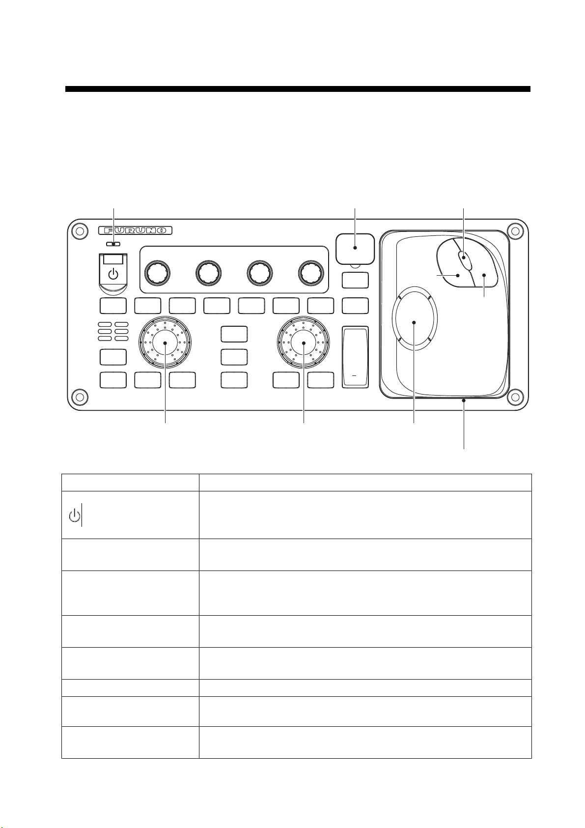
1. BASIC OPERATION
This Chapter explains basic operations using keys, knobs and boxes displayed on the screen in
the control unit. Some functions have several ways to operate but this manual explains the
simplest operations.
1.1 Using keys and knobs
USB port coverPower lamp
STDY
TX
EBL
OFFSET
ALARM
ACK
PUSH TO
HUE
BRILL A/C RAIN A/C SEA
MODE
EBL
OFF
VECTOR
MODE
EBL
ON
PUSH TO
AUTO
ECHO
TRAIL
OFF
CENTER
F1
F2
PUSH TO
AUTO
HL
OFF
MARK
VRM
OFF
PUSH TO
AUTO
GAIN
TARGET
LIST
VRM
ON
ACQ
TARGET
CANCEL
+
RANGE
EBL control VRM control Trackball
Key, knob Function
Left
button
Scrollwheel
Right
button
Trackball module
Turn ON /OFF power. Power lamp lights up when the power is turned
on. (Depends on the setting of [PANEL BRILLIANCE] on the
[BRILLIANCE DETAIL] menu.
Image brilliance Turn: Adjust brilliance.
Press: Select color.
Precipitation clutter
rejection
Turn: Reject precipitation clutter.
Press: Switch between the precipitation clutter rejection function and
the noise rejection function.
Sea clutter rejection Turn: Reject sea clutter.
Press: Select Auto or Manual of the sea clutter function.
Gain Turn: Adjust gain.
Press: Select Auto or Manual of gain.
Getting ready/Transmit Switch between Getting ready and Transmit
Mode selection Select display mode such as Head-up, Cursor gyro, North-up or True
motion, etc.
Vector True/Relative - Switch vector mode.
- Call registered function (Function key).
1

Key, knob Function
Echo trail Short press: Select trail time.
Long press: Delete trail.
Delete heading line Delete heading line while the key is being pressed.
Mark Input marks and destinations.
Target data list - Display data of all tracked target (TT/AIS)
- Call registered functions. (Function key)
Delete target Short press: Cancel selected TT track target. Stop AIS active target.
Long press: Cancel all TT track target.
Acquisition - Acquire target.
- Display/Hide data of TT target data.
EBL offset Offset/Cancel EBL offset
Cancel alarm Stop alarm sound.
EBL Knob: Operate EBL (Electronic cursor).
OFF: Delete EBL.
ON: Display EBL.
Off center Move own ship position
F1, F2 Call registered functions (Function key) .
VRM Knob: Operate VRM (variable range ring)
Range Select range for display.
Trackball section Trackball
- Move cursor.
- Select menu item.
Left button
- Fix selected item.
- Change setting inside of the box.
Wheel
- Turn: Change numerical value.
- Turn: Select menu item.
- Turn: Change setting in box.
- Press: Fix selected item.
Right button
- Display menu of each function.
- Return to one step above.
USB cover Open the cover to show an opening to insert USB memory. (for data
backup)
2
1.2 Turning ON/OFF the Power, Transmission
1.2.1 Turning the power ON/OFF
Please note the following when using the radar.
Note: Make sure to use the [
personal computer is used inside of the equipment. Turning off the power by using the breaker,
etc. instead of using the [
may prevent the machine from functioning properly. If you experience abnormal function, seek
for immediate service. Lost data are unrecoverable. Please backup your data periodically.
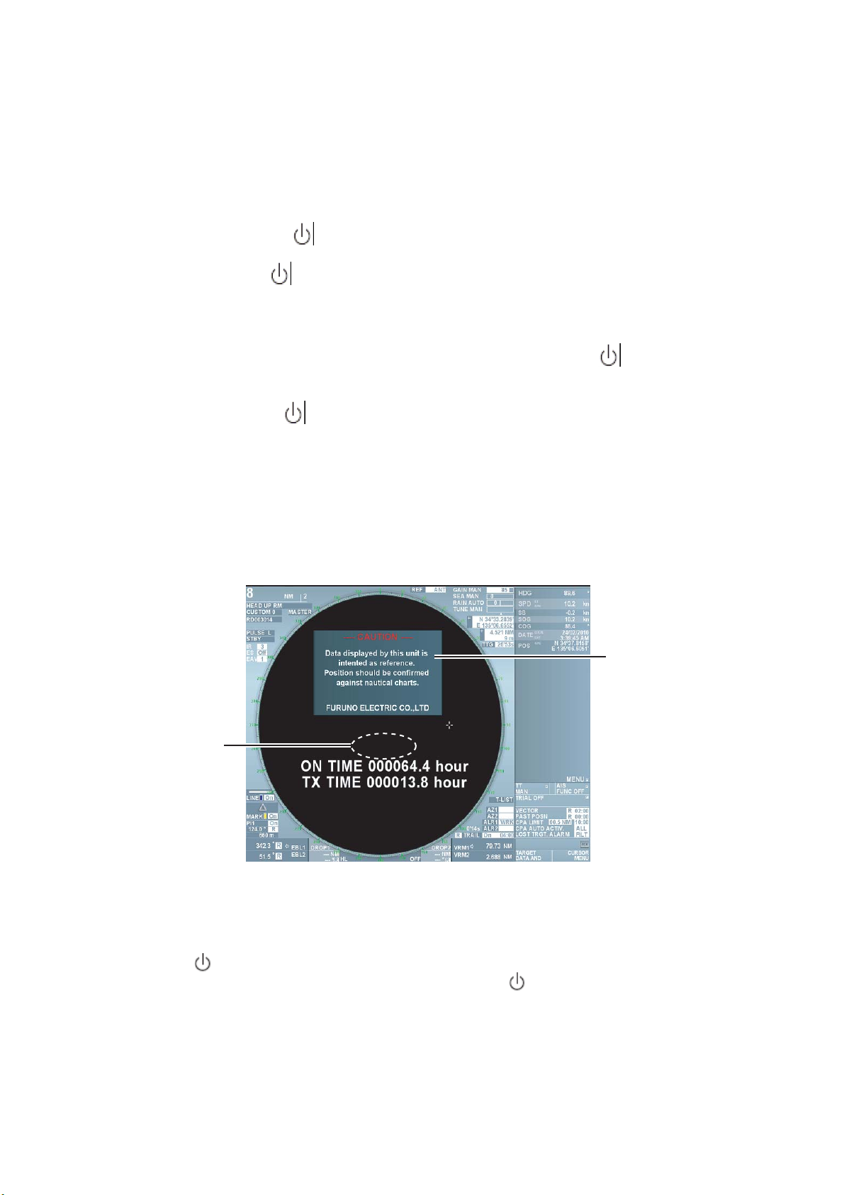
1. Open the cover at the left upper section of the control unit, press the [
radar switch on. When the slide switch of the monitor unit (MU-150HD or MU-190HD) is ON
(factory default), the power of the monitor unit is turned on automatically. When the switch is
turned OFF, press the [
power is turned on, the display on the screen changes in the order of FURUNO screen →
Machine type name screen → Getting ready screen. It takes approximately 1 and 1 ½ minutes
until the Getting ready screen appears. For FAR-1417, preheating of magnetron is completed
during this time. For FAR 1427, it starts counting down the remaining time (1 ½ minutes)
necessary for preheating magnetron. When getting ready appears on the screen, you can
start transmission. On the Getting ready screen, mark, fixed range ring, chart, TT target and
AIS target are not displayed. Left-click inside of the warning message box to erase the
warning message.
] key in the control unit when turning off the power of this radar. A
] key may cause loss of data stored inside. In the worst situation, it
] key to turn the
/ BRILL] key in the monitor unit to turn the power on. After the
Warning message
Stant count down at
[01:19], it changes
to GETTING
READY.
Note 1: Do not turn the power on while USB memory is inserted in the control unit.
The GETTING READY screen does not show when USB memory is inserted.
Note 2: When ambient temperature is low, display on the screen moves slower.
2. Press the [
down” appears at the center of the screen. Release the [
turns off in about 15 seconds.
] key in the control unit when turning the power off. The message “Shutting
01:19
] key immediately. The power
3
Quick Start
When magnetron is sufficiently warmed up, you can start the transmission without waiting full
preheating time. Press the [
] key again within 10 seconds after the power is turned off in error.
1.2.2 Switching between TRANSMISSION and GETTING READY
To start transmission, press the [Getting ready/Transmit] key while getting ready is displayed on
the screen. Radar echoes are displayed on the screen with the previously used settings of range,
brilliance, VRM, EBL and menu settings.
Each press of the [Getting ready/Transmit] key switches between getting ready and transmit.
Antenna is stopped at the time of Getting ready and starts rotating when transmission starts. Life
of magnetron shortens in proportion of transmission time. Keep the equipment in the Getting
ready state when there is no need for transmission.
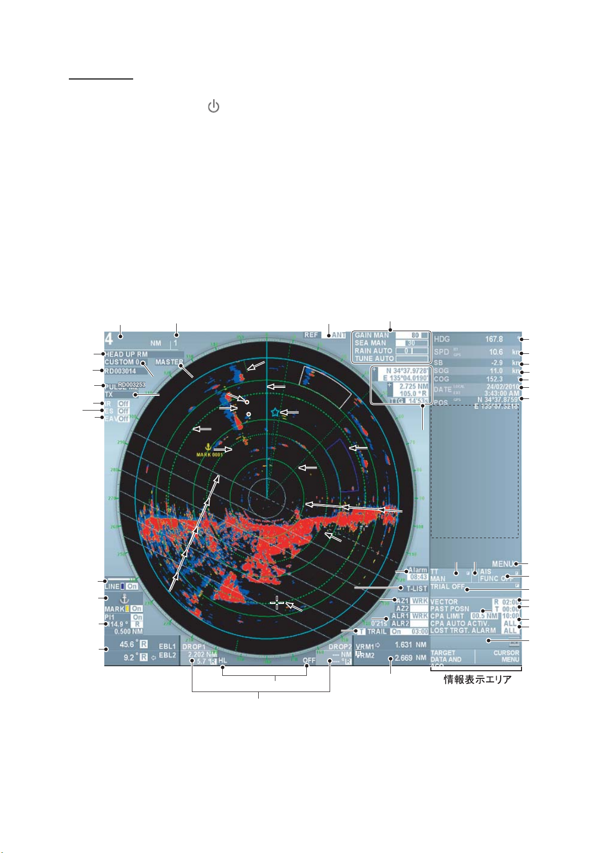
1.3 Examples of Screen Display
10
11
12
3
6
7
9
13
14
15
IR
ES
EAV
20
21
30
25
23
36
26
49
50
47
55
40
41
42
43
44
45
46
48
51
52
53
54
56
57
58
1
2
27
4
8
5
28
31
34
33
37
29
24
35
32
38
22
39
19
17
16
18
4

Explanation Explanation
1 Range 2 Fixed range ring interval
3 Display mode box 4 Image box
5 Interswitch box 6 Antenna unit box
7 Pulse length box 8 Getting ready/Transmit box
9 Noise rejection 10 Zoom out image
11 Signal processing 12 Line box
13 Mark/Destination box 14 Parallel cursor box
15 EBL1/EBL2 box 16 Drop1/Drop2 box
17 Delete heading line 18 VRM1/VRM2 box
19 Trail box 20 Guard1/Guard2 box
21 AZ1/AZ2 (Guard zone) box 22 Display list of target data
23 Watch alarm box 24 Reference position box
25 Gain, Sea clutter, Precipitation clutter (or
un unwanted echoes), Tuning adjustment
27 North mark 28 TT target
29 Heading line 30 Guard alarm range
31 EBL2 32 EBL1
33 AIS target 34 VRM2
35 Drop 1 mark 36 Fixed range ring
37 Parallel cursor 38 VRM1
39 Cursor 40 Heading
41 Ship speed toward heading (Speed over
ground or Speed over water), Data input
source
43 Speed over ground 44 Over the ground course
45 Date, Time 46 Own ship’s latitude/longitude, Data input
47 Display of navigation data, zoom window,
TT data, AIS data
26 Cursor data box
42 Ship speed in starboard direction
source
48 Display main menu
49 TT box 50 Identification box
51 AIS box 52 Simulate steering box
53 Vector box 54 Track interval box
55 Set CPA/TCPA 56 Set Auto activation function
57 Set lost target alarm 58 Alarm list
5
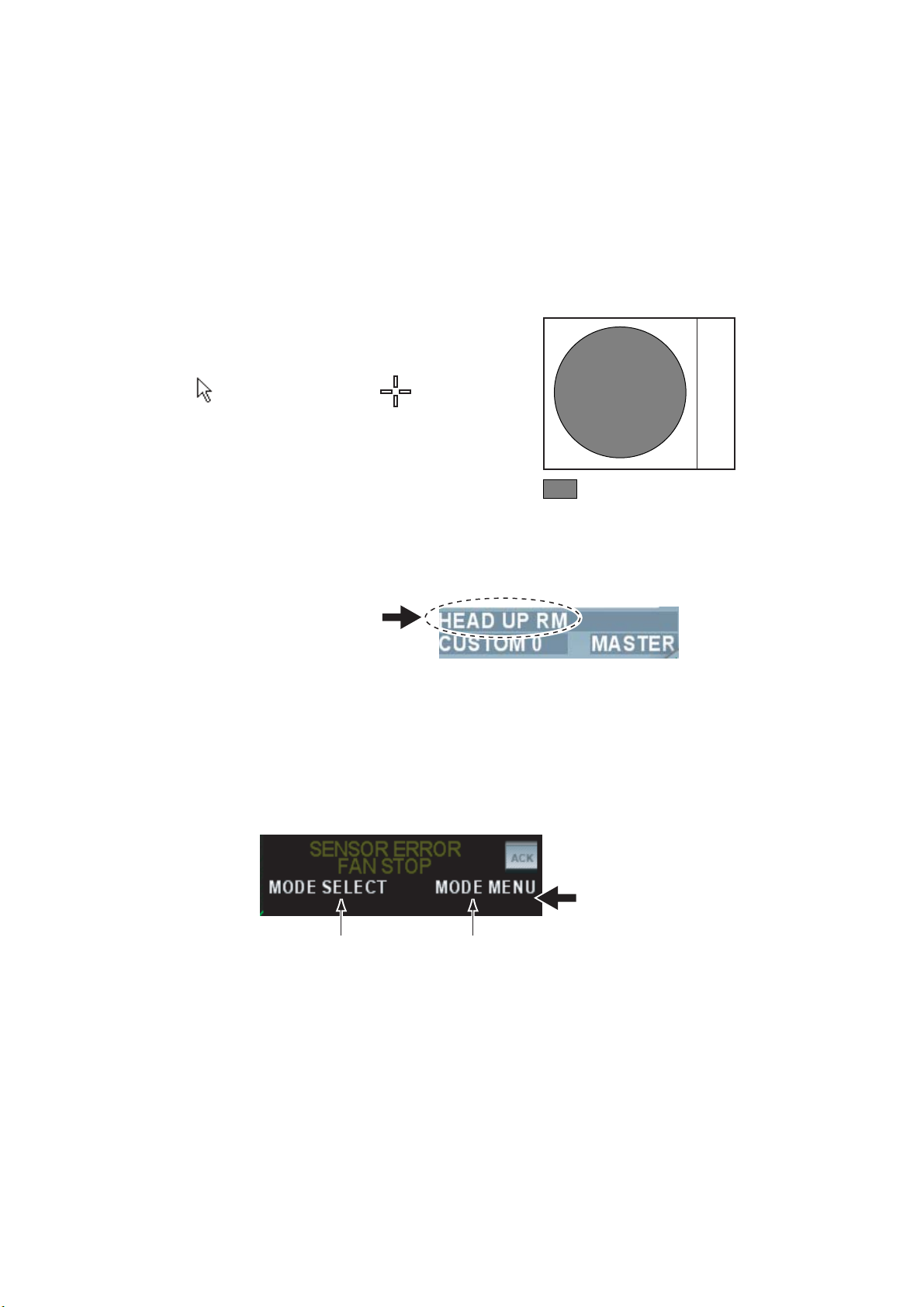
1.4 Operating from boxes on the screen
Users can perform all the operations from the trackball area alone. Select a box on the screen
with the trackball and select an item with the left/right button or the wheel. (See chapter 1.3 for
box positions.)
Follow the steps below to use boxes on the screen.
1. Roll the trackball and place the cursor on the box required. Shape of the cursor changes as
shown in the figure below depending on positions of the cursor.
Cursor is not within the
valid area for
displaying images.
Cursor is within the
valid area for
displaying images.
: Valid area for displaying
radar images.
For example, select the display mode box on the left upper side on the screen.
Display mode box
When a box is selected correctly, color of texts inside of the box (or the box) changes. A function
when you press the button next is displayed in the guide column in the information display area.
The screen shows the left button functions on the left side of the vertical line and the right button
functions on the right side of the vertical line. In this example, the display mode box is selected
and [Select mode/Mode menu] is displayed on the screen. Select the display mode with the left
button and display the [Display mode] menu with the right button.
Guide column
Function of the left button
The bottom section of the information display area
on right side of the screen.
2. Press the left button or the right button to select a necessary item.
In this manual, “left-click” means to press the left button and “right-click” means to press the
right button.
Note: You can also select an item inside of the box by rolling the wheel instead of using the left
button. The color of the item changes when you select the item by rolling the wheel, which
means that the setting has changed from the current setting. To change the setting to another
setting, press the wheel or the left button to set the selection. If the selection is not set after
selecting the item by rolling the wheel, the setting returns to the previous setting.
6
Function of the rigth button

1.5 Brilliance and Color Scheme
1.5.1 Adjusting brilliance
Brilliance of the entire screen can be adjusted from the monitor or the control unit. To adjust
brilliance from the control unit, the monitor settings need to be changed.
Adjusting brilliance Monitor settings
Short press the [ / BRILL]キー Set [EXT BRILL CTRL] at [OFF] in the
[SYSTEM] menu (Factory default)
Rotate the [Image brilliance] knob in the control
unit.
Set [EXT BRILL CTRL] at [USB] in the
[SYSTEM] menu.
1.5.2 Selecting color scheme
This equipment provides eight sets of color and brilliance depending on any ambient lighting
conditions. The following table shows the factory default of color and brilliance sets.
Sets Screen
brilliance
Day 100% White White Orange Green Light gray
Dusk-Green 50% Green Green Orange Green Black
Dusk-White 50% White text
Night-Red 20% Red Red Orange Red Dark gray
Night-Blue 20% White text
Black 100% Black Red Orange Red Black
Custom 1 100% White White Orange Green Light gray
Color Text Echo Fix range
ring
White Orange Green Blue
on blue
White Orange Green Blue
on blue
Background
Custom 2 100% White White Orange Green Light gray
Press the [Image brilliance] knob to select color scheme. Each press of the knob switches
between the color sets of Day, Dusk-Green, Dusk-White, Night-Red, Night-Blue, Black, Custom
1 and Custom 2. User can register desired color sets from Custom 1 and Custom 2. (See
chapter 2.9)
Note: Brilliance of marks and texts displayed on the screen can be adjusted by color scheme.
(See chapter 2.9)
7
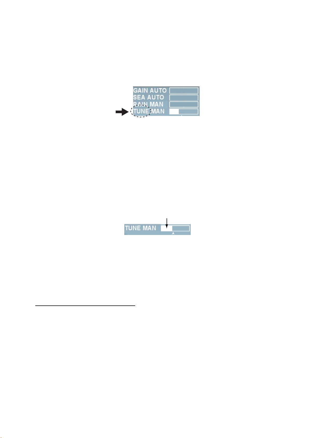
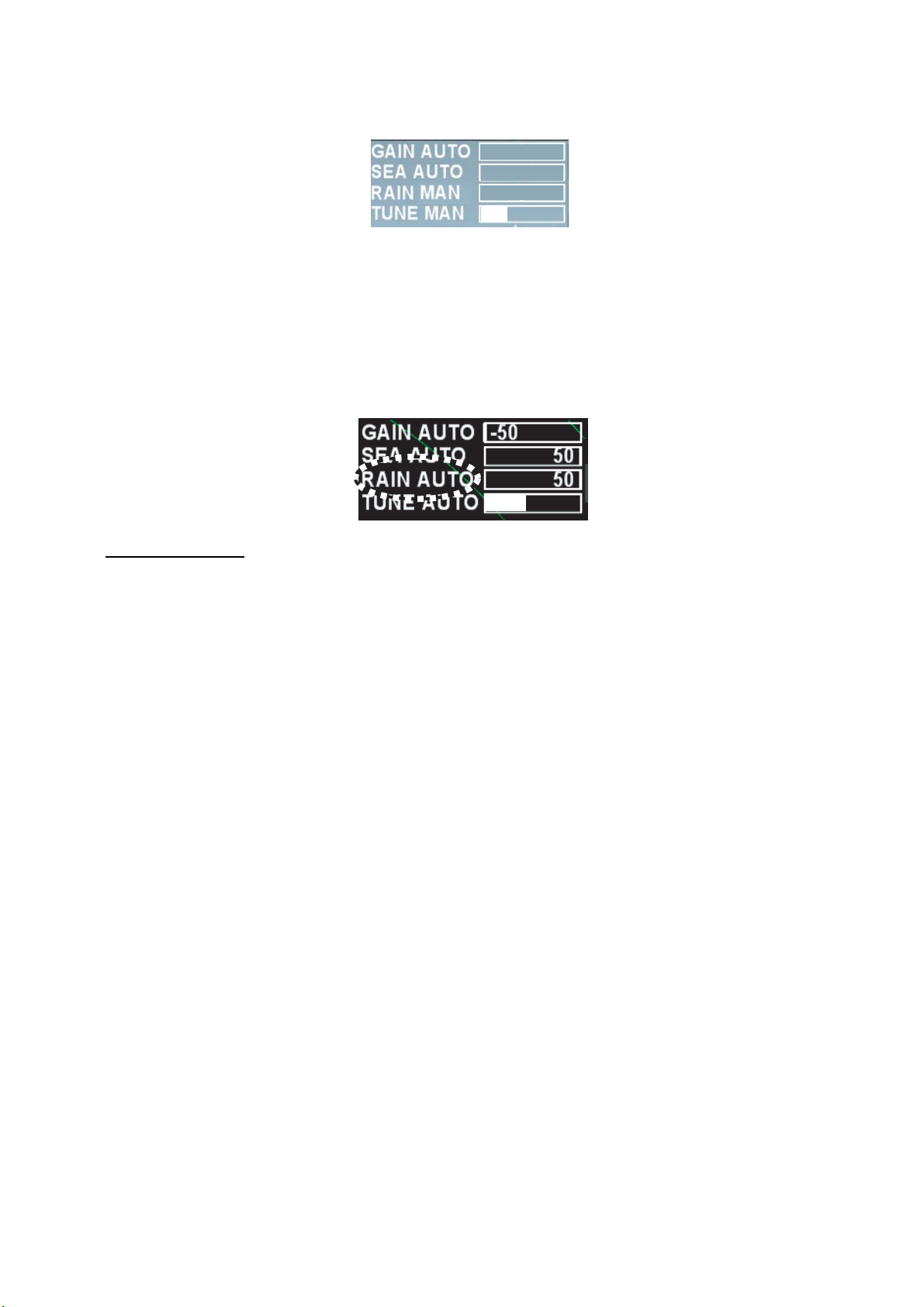
1.6 Tuning
1.6.1 Choosing the tuning method.
User can choose either automatic or manual tuning.
1. Roll the trackball to place the cursor on [Tuning] at the upper right section on the screen.
-50
50
0
2. Left-click to select [Manual] or [Auto]. Each click switches the displays. [Auto] triggers the
function to tune the image clearly. Refer to Chapter 1.6.2 for [Manual] setting.
Note: If automatic tuning does not show clear images, try initializing tuning. (See chapter
2.10.11.)
1.6.2 Manual tuning
Follow the following steps for manual tuning.
1. Press the [Range limit] key several times to set it at 48NM.
2. Roll the trackball and place the cursor on the tuning bar.
3. Roll the wheel to adjust the tuning bar at maximum.
Tuning bar
1.7 Display Modes
This radar has the display modes of Head-up, Cursor gyro, Stern-up, Course-up, North-up and
True Motion. Each display mode is explained in Chapter 1.7.2. Display modes except Head-up
and Stern-up need heading signal. For True Motion, connection to GPS navigation equipment is
necessary. The true-view display function enables smooth rotation of radar echo in accordance
with own ship’s turns in Head-up, Cursor gyro and Stern-up modes only.
When Gyrocompass is connected
Gyrocompass readings and heading values in the information display area of this equipment
need to be matched accurately when receiving analog signal (Synchronization or Step signal)
from gyrocompass. (Setting method: Main menu → Echo → GC-10, See chapter 2.11.1.)
8
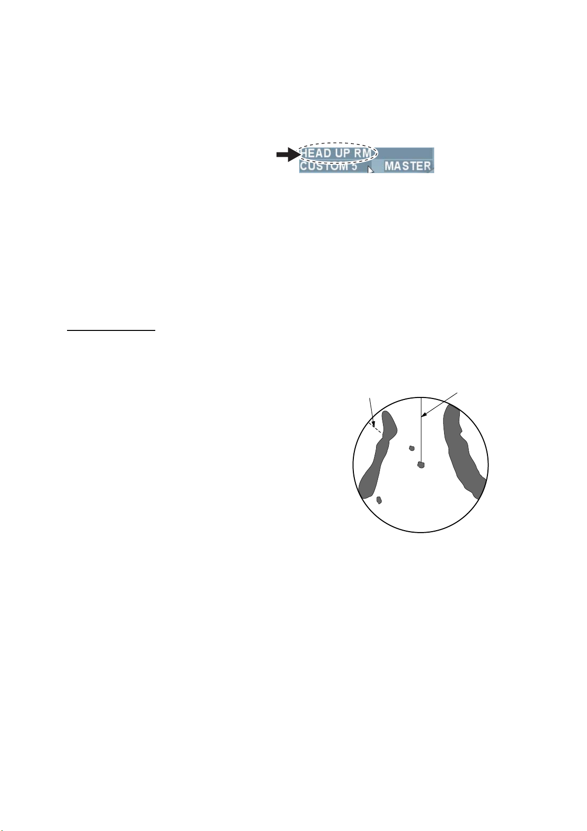
1.7.1 Selecting display mode
Press the [Select mode] key several times to select display mode necessary. Name of the
display mode currently being selected is displayed in the display mode box at the upper left
section on the screen.
Presentation mode box
Note 1: When heading signal is interrupted, the blinking message “Sensor Error Gyro” appears
in the alarm section in the information display area. Heading reading in the information display
area becomes “xxx°” and the North mark disappears and the monitor mode automatically
becomes the head-up mode. When heading signals are restored, select the monitor mode with
the [Select mode] key again.
Note 2: User can pre-set appropriate monitor mode to use. (See chapter 2.10.2.)
1.7.2 Description of display modes
Relative motion
In relative motion, own ship position is stationary on the screen to observe relative motion of
surrounding targets.
• Head-up
The head-up mode is a display in which the line
connecting the own ship and the top of the display
indicates own ship’s heading. Targets are displayed as if
they were viewed from the bridge. Therefore, this mode
is suitable for navigating through narrow channels and
crowded waters. On the other hand, target images may
fluctuate due to own ship’s turning and yawing.
A short line on the bearing scale is the north marker
indicating heading sensor north.
Noth maker
Heading line
• Cursor Gyro
It is the same screen as Head-up but bearing scale links to heading signal. The cursor gyro can
be used only when bearing sensor is connected to the radar. A failure of the bearing sensor will
cause the bearing scale to become the same as that in the head-up mode.
• Stern-up
The stern-up mode rotates the head-up mode picture 180° showing ship’s stern on top of the
display at all times.
• Course-up
The course-up mode is an azimuth-stabilized display in which a line connecting the center with
the top of the display indicating own ship’s intended course (harbor, destination, etc.) Own ship’s
heading moves in accordance with changes of its course indicating the initial bearing on the top
at all times to see errors between the set course and the current course. Target images do not
fluctuate at own ship’s turning and yawning to get stable images.
9
North maker
Heading line
Heading line
At the moment when the
course-up mode is set.
Heading line tums in accodance
with changes of heding
• North-up
The true north is at the top of the screen (0°) and the heading line changes its direction
according to the ship’s course. In this mode, fixed targets are shown as if they were viewed on a
chart. Targets on the screen do not fluctuate at own ship’s turning and yawning to get stable
images. This mode is suitable for ocean voyages, ship positioning and course monitoring, etc.
North marker
Heading line
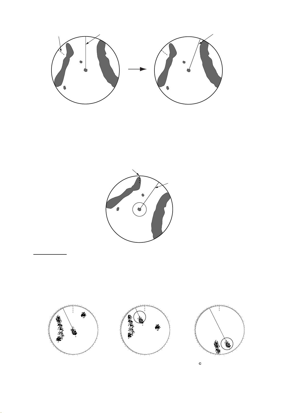
True Motion
Like looking at charts, all fixed targets such as landmasses appear as stationary echoes and
own ship moves on the screen. When own ship reaches a point corresponding to 75% of the
radius of the display, own ship position is automatically reset to a point of 75% radius opposite to
the extension of the heading line passing through the display center to continue moving on the
screen. Own ship’s position can be automatically moved to 75% radius opposite to the course at
any time while in the true motion.
350
340
330
320
310
300
290
280
270
260
250
240
230
220
210
200
190
(a) True motion is
selected
000
010
020
030
040
050
060
070
080
090
100
110
120
130
140
150
160
170
180
320
310
300
290
280
270
260
250
240
230
220
(b) Own ship has reached a
point 75% of display radius
000
350
010
340
330
210
200
020
030
040
050
060
070
080
090
100
110
120
130
140
150
160
190
170
180
320
310
300
290
280
270
260
250
240
230
220
) Own ship is
(
automatically reset to
75% of radius
000
350
010
340
330
210
200
020
030
040
050
060
070
080
090
100
110
120
130
140
150
160
190
170
180
10
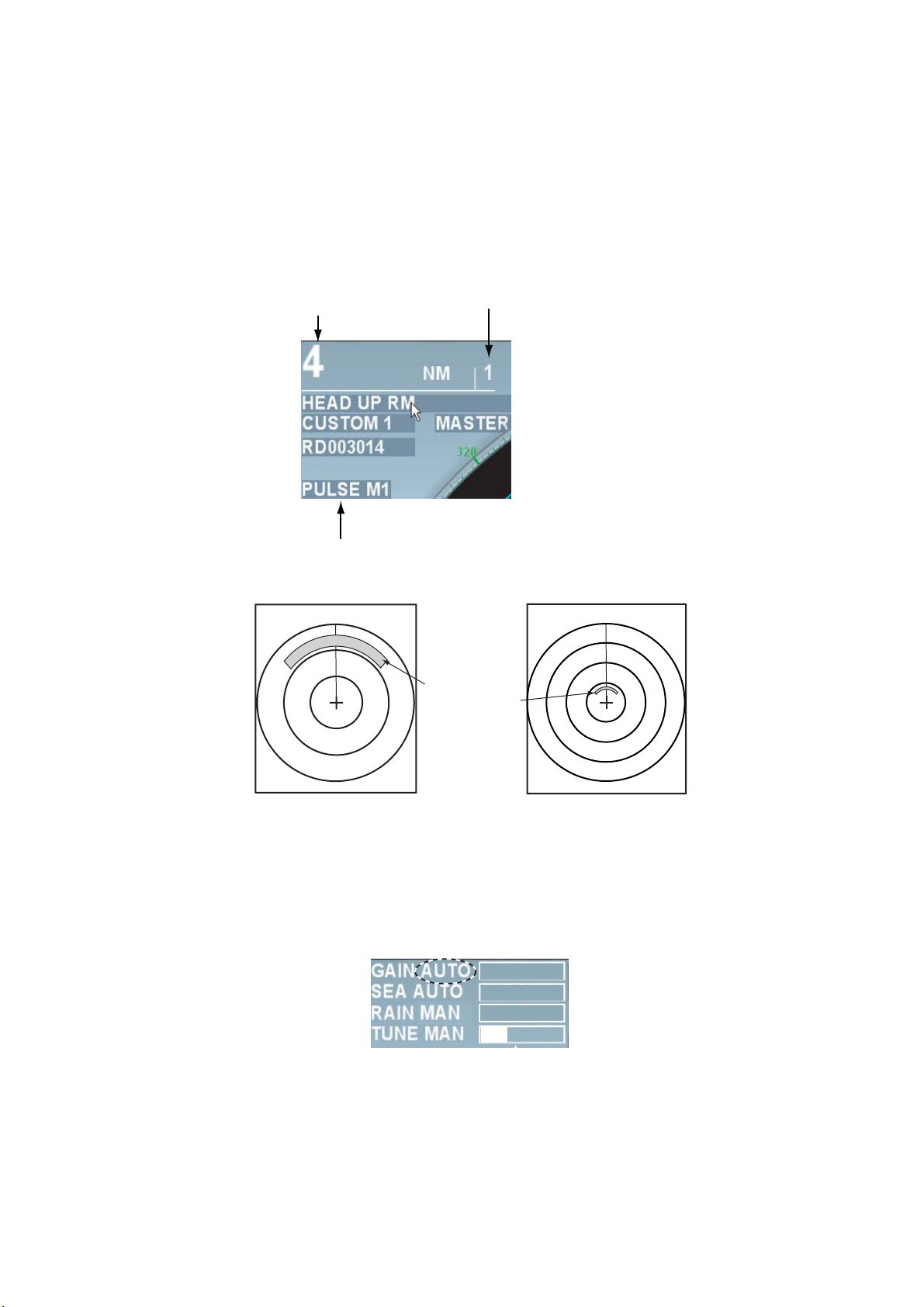
1.8 Selecting range
The selected range scale, range ring interval and pulse length are shown at the upper left corner
of the screen. When a target of interest comes closer, reduce the range scale so that it appears
in 50~90% of the display radius.
Press the [Range] key several times to select range desired. Hit the “+” part of the key to raise
the range and “-”part to lower the range. When range is switched, range ring interval and pulse
length also change automatically.
Small range
NM
3
Range
Pulse length
Fixed range ring interval
12
Same object
appears in
different
sizes.
Large range
NM
1.9 Adjusting Gain
To properly display targets at all times, it is necessary to adjust gain in accordance with signal
strength. Gain can be adjusted automatically or manually.
1. Press the [Gain] knob to select the method of gain adjustment. Each press of the [Gain] knob
switches between [Auto] and [Manual].
-50
50
0
2. For automatic adjustment, roll the [Gain] knob according to sea condition to fine tune the
sensitivity. (Range: -50 ~ +50) For manual adjustment, roll the [Gain] knob to tune the
sensitivity. (Range: 0 ~ 100)
Note: For manual adjustment, adjust the gain control so that the background noise is just visible
on the screen. If the gain level is too low, weak echoes may be missed. On the other hand, if the
gain level is too high, the strong background noise may hide weak targets.
11
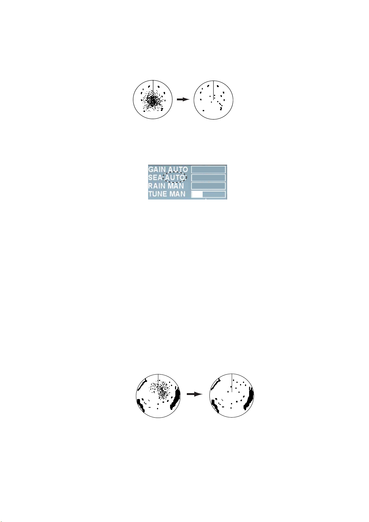
1.10 Rejecting Sea Clutter
Strong sea clutter occurs around own ship in bad weather due to strong reflection from sea
surface to prevent identification of targets on the screen. In such a case, use the sea clutter
rejection function to control sea clutter. Sea clutter can be rejected automatically or manually.
Sea clutter appears
at the center of the
screen.
Sea clutter is rejected.
Sea clutter rejection function
1. Press the [Sea clutter rejection] knob to select the method of sea clutter rejection. Each
press of the [Sea clutter rejection] knob switches between [Auto] and [Manual]. The control
sea clutter is automatically set at optimum level when the setting is [Auto].
-50
50
0
2. For automatic rejection, roll the [Sea clutter rejection] button according to sea conditions to
fine tune the setting. (Setting range: -50 ~ +50) To reduce sea clutter, increase the setting
value toward [+] and to increase sea clutter toward [-].
3. For manual rejection, roll the [Sea clutter rejection] knob while observing echoes on the
screen to reject sea clutter. (Setting range: 0 ~ 100)
Note: For manual adjustment, do not set the sea clutter rejection level too high. When the sea
clutter rejection level is too high, it may miss approaching targets. Normally set the level just so
weak sea clutter appears on the screen. Set the sea clutter rejection level at 0 (the minimum)
when there is no sea clutter appearing on calm sea surface.
1.11 Rejecting Precipitation Clutter
Radio waves transmitted from antenna are reflected on rain and snow to appear on the screen
as precipitation clutter. The function of precipitation clutter rejection is used when unwanted echo
covers up and hides targets. The precipitation clutter rejection is controlled in the similar way as
the sea clutter rejection but it becomes effective not only in near range but in longer range as
well. The higher the setting, the greater the anti-clutter effect becomes.
Unwaned echoes are displayed.
(Toward the starboard)
Function of precipitation rejection
1. Press the [Precipitation clutter rejection] knob to select the function of precipitation clutter
rejection. Each press of the [Precipitation clutter rejection] switches between [Precipitation
clutter manual] and [Unwanted echo]
Precipitation rejection
control adjusted.
12
2. Roll the [Precipitation clutter rejection] knob while observing the screen to reject the
precipitation clutter. (Setting range: 0 ~ 100)
-50
50
0
1.12 Automatic rejection of sea clutter and
precipitation clutter
When sea clutter and precipitation clutter cannot be removed fully, press the [Precipitation clutter
rejection] knob to select the unwanted echo rejection function. “Unwanted echo” is displayed at
the upper right section on the screen while the unwanted echo rejection function is working.
Notes on usage
• Echoes covering wide areas such as lands and islands may become smaller.
• Clutter or strong precipitation clutter more than necessary. In such a case, use the functions of
sea clutter rejection or precipitation clutter rejection to manually adjust the echo level at
optimum.
1.13 Deleting heading line temporarily
Heading line is displayed in all display modes and shows the own ship’s heading. Heading line
appears directly above own ship (0°) in the head-up mode and the cursor gyro mode. Heading
line appears directly under own ship (180°) in the stern-up mode. In the north-up, true motion
and course-up modes, heading line moves in accordance with own ship’s direction. Thickness
and color of heading lines can be changed in the [Mark] menu. (See page 2-31.)
To confirm small targets in heading direction press the [Delete heading line] to temporarily delete
the heading line. All the marks on the heading line and radar screen disappear and only targets
are displayed while this key is being pressed
13
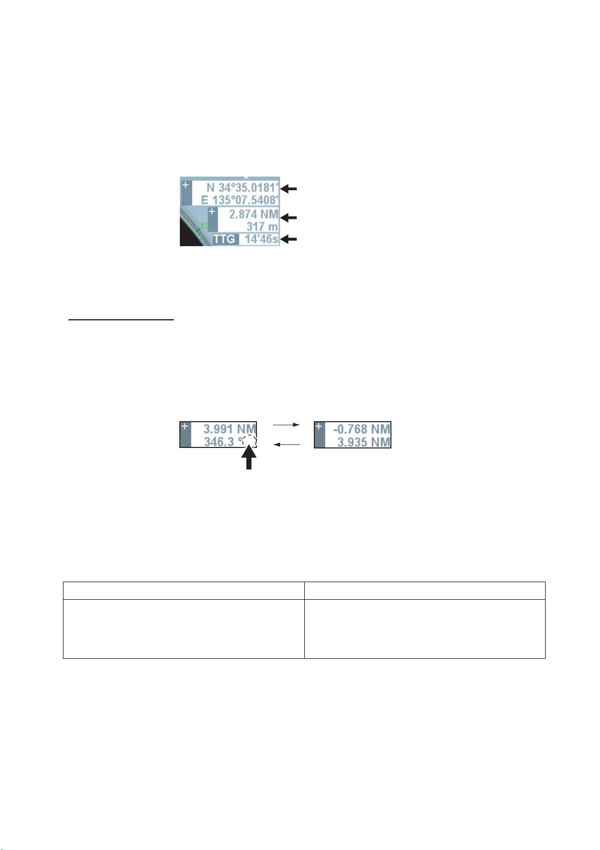
1.14 Cursor position
User can measure range and bearing from own ship to target and see latitude and longitude of
target position.
Roll the trackball and put the cursor on target to display information at the cursor position in the
cursor data 1 and cursor data 2 boxes. [---] is displayed when the cursor is outside of the
effective radar range.
Cursor Data 1 Box
Cursor Data 2 Box
Time required before arrival
Cursor Data 1 Box: Displays latitude/longitude of cursor position.
Cursor Data 2 Box: Displays range/bearing from own ship to cursor position or X-Y
coordinates.
Cursor Data 2 Box
Do the following to switch displays of Cursor Data 2 Box.
1. Roll the trackball to put the cursor on Cursor Data 2 Box at the upper right side on the screen.
2. Left-click to select the display method.
Each click switches the displays.
Range/Bearing from
own ship cursor
R
Click here to switch
bearing reference.
Left click
X-Y coordinates
True: True bearing
Rel.: Relative bearing
Note 1: When the reference position at the upper screen is [Steering position], range/bearing
from the steering position is displayed and when the reference position is [Antenna],
range/bearing from the antenna position is displayed.
Note 2: The table below shows the relationship between X-Y coordinates and bearing reference.
Bearing reference REL Bearing reference TRUE
Y-axis indicates heading line. Heading direction
is plus (+) and stern direction is minus (-).
For X-axis, the starboard direction is plus (+) and
the port direction is minus (-)
14
Y-axis indicates South/North. North direction is
plus (+) and South direction is minus (-).
X-axis indicates East/West. East direction is plus
(+) and West direction is minus (-).

1.15 Measuring range to target
There are three methods to measure range to target; fixed range ring, Cursor (See chapter
1.14.) and VRM (Variable Range Ring).
1.15.1 Using Fixed Range Ring
Fixed range ring (Concentric circle with own ship at its center) is used to make a rough
measurement. Fixed range ring interval is displayed at the upper left side on the screen.
Range between own ship and a target is estimated from the nearing fixed range ring
closest from the target by counting number of fixed range rings.
Note 1: Number of fixed range ring is determined in accordance with range selected. However,
the number can be selected manually. (See chapter 2.10.1.)
Note 2: Each left-click switches between ON/OFF of fixed range ring while cursor is put on the
fixed range ring interval (numerical value).
1.15.2 Using VRM (Variable Range Ring)
There are two types of VRM; VRM1 and VRM2, which are shown by broken lines to distinguish
from fixed range ring. The two types of VRM can be distinguished from each other by the length
of the broken line also. VRM1 has shorter broken lines and VRM2 has longer broken lines.
1. Press the [VRM ON] key to display VRM.
2. Roll the [VRM] knob to put VRM on the inner side of target to which range you want to
measure. Read range displayed at the lower right side on the screen. VRM value remains
even when range is changed.
3. Press the [VRM OFF] key to delete VRM. The way it is deleted varies according to display
condition of VRM.
• When both VRM1 and VRM2 are displayed and either VRM1 or VRM2 is in operable
condition, either VRM2 or VRM1 whichever is not in operable condition disappears.
• When either VRM1 or VRM2 is displayed, the VRM of the displayed one disappears.
15
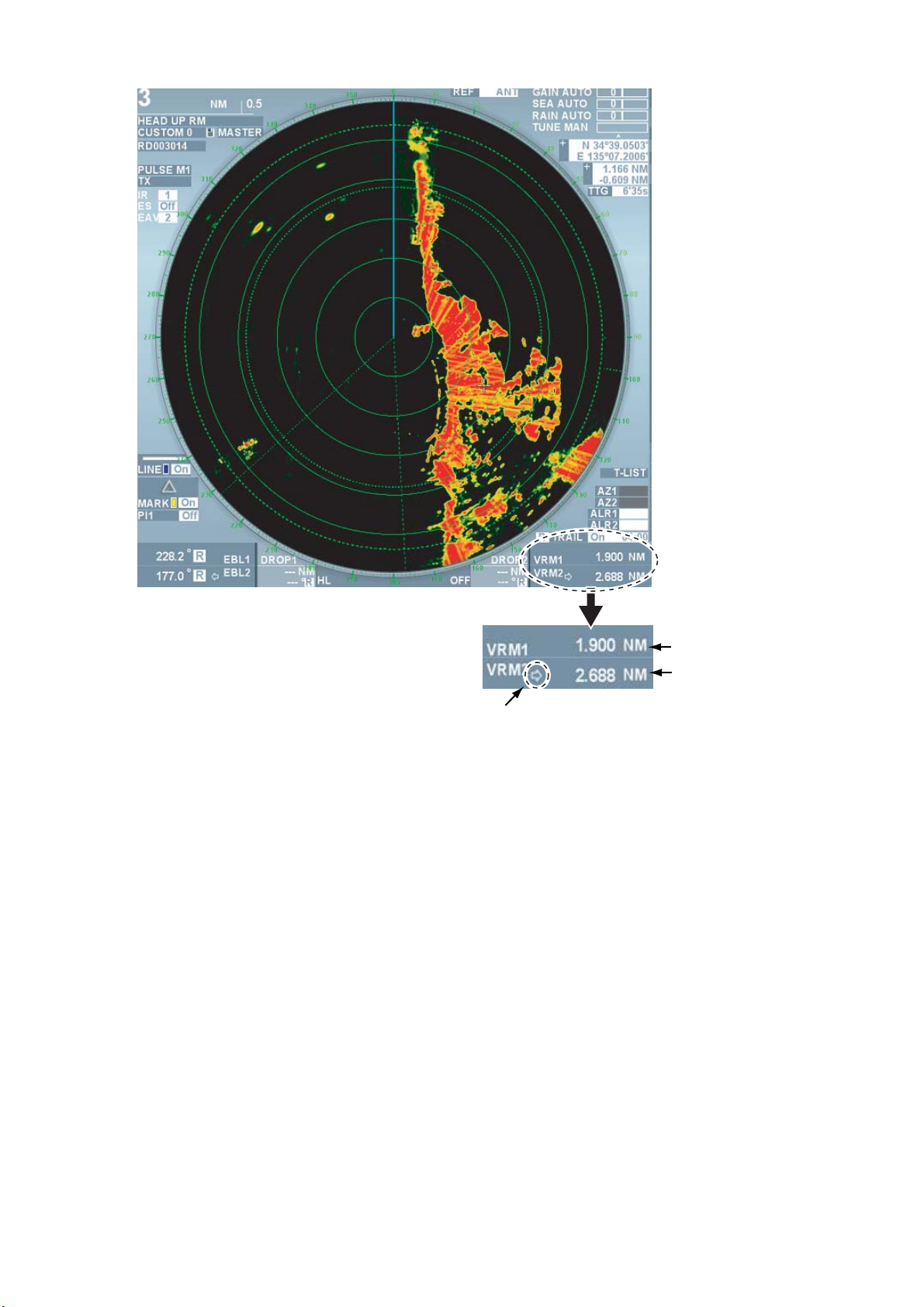
Range to VRM1
Range to VRM2
Currently operable VRM
(with arrow mark)
VRM box
Range by VRM
Note: Unit of VRM can be changed in the [Edit image] menu. (See chapter 2.1.4.)
1.16 Measuring bearing of target
Use the Electronic Bearing Lines (EBL) to take bearing of targets. There are two EBLs, No.1 and
No.2. Each EBL is a straight broken line extending out from the own ship position to distinguish
from heading line. The two EBLs can be distinguished from each other by the different length of
their dashes; dashes of EBL1 are shorter than EBL2.
1.16.1 Measuring bearing using EBL (Electronic cursor)
1. Press the [EBL ON] key to display either of the EBLs. Each press switches the arrow in the
box between EBL1 and EBL2. The EBL with the arrow mark can be operated with the [EBL]
knob.
2. Roll the [EBL] knob to put the EBL on the center of the target of interest Read its bearing at
the lower left corner on the screen.
3. condition of EBL.
• When both EBL1 and EBL2 are displayed and either EBL1 or EBL2 is in operable
condition, the one that is not in operable condition disappears.
16
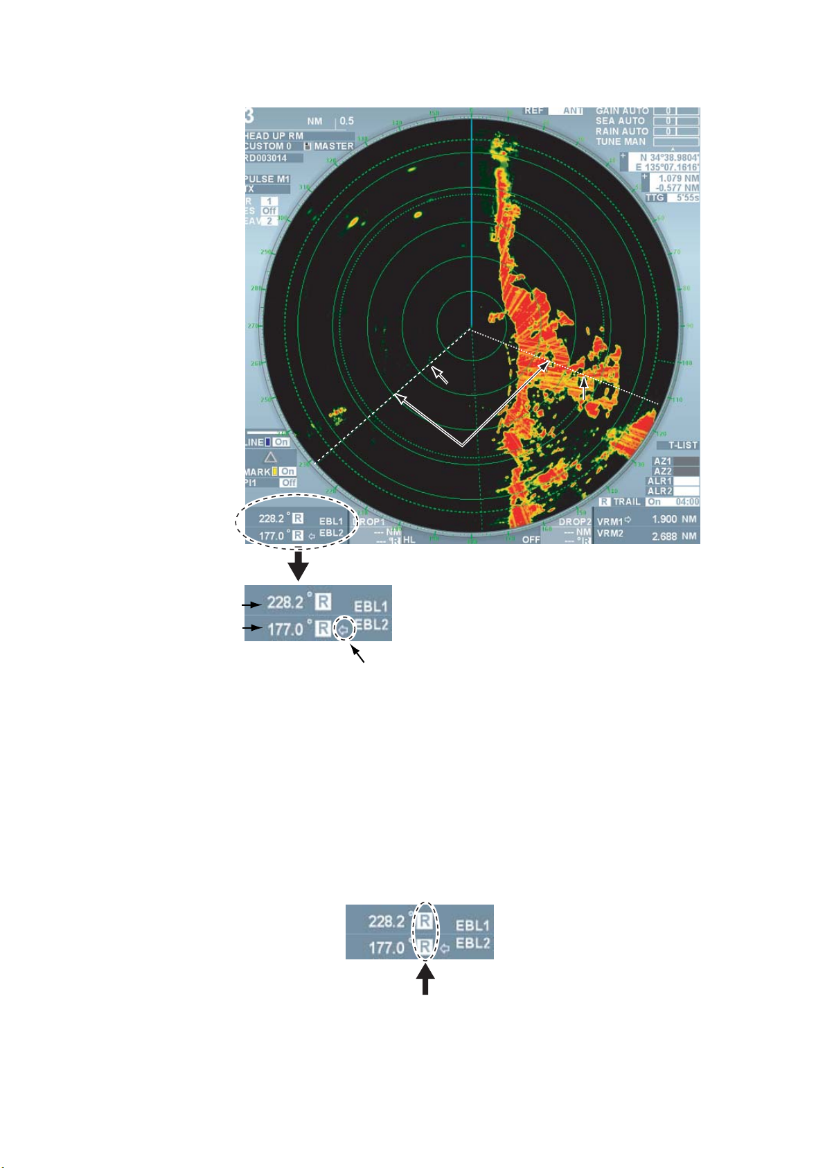
• When either EBL1 or EBL2 is displayed, the EBL on the displayed one disappears.
EBL2
EBL1
Range maker
Bearing of EBL1
Bearing of EBL2
EBL box
Currently operable EBL
(with an arrow)
Measuring Bearing with EBL
1.16.2 Selecting Bearing Reference of EBL
EB L values can be displayed by either REL (relative bearing referenced to own ship’s heading)
or TRUE (true bearing referenced to the north). Heading bearing signal is necessary to display in
true bearing.
1. Roll the trackball to put the cursor on REL or TRUE in the EBL box at the lower left corner on
the screen.
2. Left-click to select either REL or TRUE.
17
1.17 Measuring Range and Bearing between Two
Targets
Range and bearing between two targets can be measured by moving EBL origin.
1. Press the [EBL ON] key to display EBL1.
2. [Press the EBL offset] key. The EBL origin moves to the cursor position.
3. Roll the trackball to move the cursor on target A.
4. Roll the [EBL] knob to put EBL1 at the center of target B.
5. Press the [VRM ON] key to display VRM1.
6. Roll the [VRM] knob so that VRM1 touches target B. Range and bearing between the two
targets are displayed at the lower section on the screen. Press the [EBL offset] key to return
the EBL origin to the center of the screen.
Bearing/Range between target A and B
Similarly, range and bearing between target C and target D can be measured using EBL2 and
VRM2.
Note: User can select the method of fixing origin of EBL offset. (See page 2-31.)
Bearing/Range between target C and D
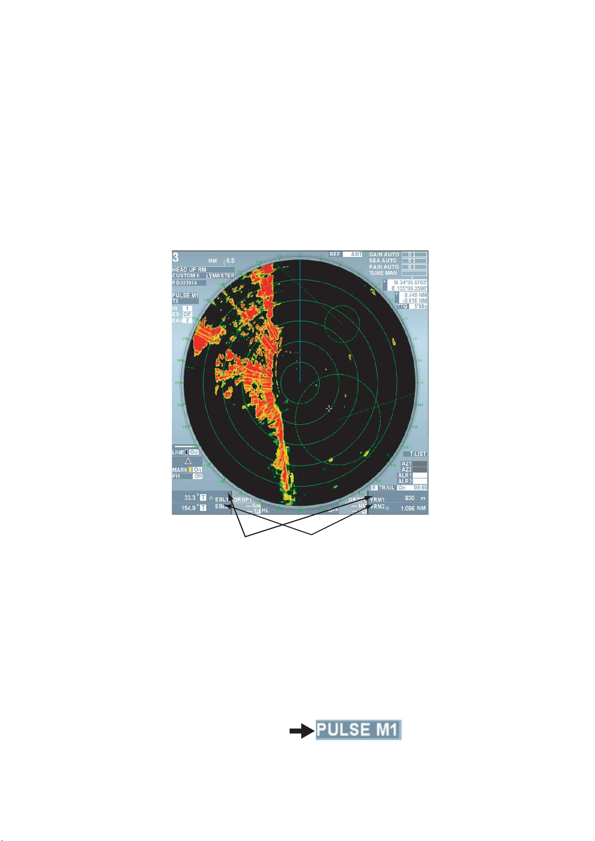
1.18 Selecting Transmission Pulse Length
Transmission pulse length is displayed at the upper left side on the screen. Pulse length can be
changed according to situations except for far range. To emphasize far range detection, extend
the pulse length and to emphasize resolution, shorten the pulse length. Shortening pulse length
can also reject precipitation clutter.
1. Roll the trackball to put the cursor on the pulse length box at the upper left side on the screen.
Pulse length box
2. Left-click to shorten the pulse length and right-click to lengthen the pulse length.
Each click switches between available pulse lengths in the current range scale.
18

1.19 Off-Centering the Display
Own ship position, or sweep origin, can be displaced to expand the view field without switching
to a larger range scale. The sweep origin can be off-centered to the cursor position, but not more
than 75% of the range in use. In the true dynamic mode, the sweep origin can be off-centered to
the cursor position within 50% of the range in use.
Note: This function can be used for ranges other than 96NM and 120NM ranges.
1. Roll the trackball to move the cursor to a position where you wish to center the image.
2. Press the [OFF CENTER] key. Own ship position moves to the cursor position.
3. Press the [OFF CENTER] key again to return the own ship position to the previous position.
1.20 Rejecting Interference
Mutual radar interference may occur in the vicinity of another
ship borne radar operating in the same frequency band. (X
band: 9GHz) It is seen on the screen as a number of bright
spikes either in irregular pattern or in the form of dotted lines
extending from the center of the edge of the picture. This
type of interference can be rejected by the interference
rejecting function.
1. Roll the trackball to put the cursor on the box next to the [Interference] at the upper left side
on the screen.
2. Left-click to select the strength of interference rejection. Each click switches between OFF
→1→2→3. The larger the value, the stronger the interference rejection, however, it may
weaken ship’s echo.
Note: Set the level of interference rejection function at OFF when there is no interference
from other ships to avoid missing small targets near own ship.
Interference by other ships radar
1.21 Echo Stretch
The echo stretch feature enlarges targets in the range and bearing directions to make them
easier to see. There are three levels of echo stretch, 1, 2 and 3. We recommend the level 3 for
normal use.
Note: The echo stretch magnifies not only small target pips but also clutter from sea surface,
precipitation and radar interference. For this reason, make sure these types of interference have
been sufficiently reduced before activating the echo stretch function.
1. Roll the trackball to put the cursor on the box next to [Stretch] at the upper left side on the
screen.
19

2. Left-click to select the desired setting. Each click switches between OFF→1→2→3. Set the
echo stretch level while observing the screen.
• OFF: no stretch
• 1: Smooth eco
• 2: Stretches 1.2 ~ 1.5 times in the bearing direction
• 3: Stretches in range and bearing directions.
1.22 Signal Processing Function
Rejecting sea clutter may also reject necessary targets. In such a case, the signal processing
function can suppress sea clutter while maintaining targets.
Note 1: Heading bearing signal and own ship positioning data are necessary for the signal
processing function
Note 2: Do not use the signal processing function in rough conditions of pitching and rolling of
own ship to avoid loss of target.
Note 3: Targets moving at high speed become difficult to detect compared of static targets when
using the signal processing function. Prior to using the signal processing function, use the sea
clutter rejection function just so some weak sea clutter appears on the screen.
1. Roll the trackball to put the cursor next to [Processing] at the upper left side on the screen.
2. Left-click to select the desired setting. Each click switches the setting between
OFF→1→2→3→4→5. Set a value while observing the echoes.
• Off: Set the signal processing function OFF.
• 1,2: Effective for target detection in sea clutter. The signal processing 2 is more effective
compared with the signal processing 1 for target detection in strong sea clutter. However,
detecting targets moving at high speed on the screen is more difficult for the signal
processing 2 compared with the signal processing 1. Use either the signal processing 1
or 2 in accordance with user’s purpose. When detecting targets in sea clutter and targets
moving at high speed simultaneously, it becomes effective to use the signal
processing function together with the wiper processing (See page 2-20.)
3. Detect weak targets, such as floats, in stormy weather.
4. Detect weak targets, such as floats, in stormy weather. To use this setting, set the
equipment as follows:
• Set the interference rejector to 3. This raises the sensitivity against weak targets.
• Manually set the gain to 80.
• Manually set the A/C SEA to 50.
• Manually set the A/C RAIN to 40. This is effective for reducing unwanted clutter and
suppressing false echoes.
5. Effective for detecting high speed targets and unstable echoes.
20
 Loading...