

Furuno USA 9ZWRTR105 Users Manual
2. WIRING
2.1 Overview
Cabling considerations
To lessen the chance of picking up electrical interference, avoid where possible routing the antenna cable (power and LAN lines) near other onboard electrical equipment
(radars, TX radio antennas, etc.). Also avoid running the cable in parallel with power
cables. When crossing with other cable, the angle must be 90° to minimize the magnetic field coupling.
The antenna cable between the antenna and processor units is available in lengths of
15 m, 30 m, 40 m, and 50 m. Whatever length is used, it must be unbroken; namely,
no splicing allowed. Use the antenna cable as short as possible to minimize attenuation of the signal.
The radar must be connected to an emergency power source, as required by SOLAS
II-1.
About network construction
• Use the optional Switching Hub HUB-100 to connect the sensor networks. For the gateway networks, use the optional Intelligent Hub HUB-3000.
• Do not connect the ship’s LAN network to the optional HUBs. Also, commercial PCs
cannot be connected to the gateway network, other than for maintenance.
• To connect the FEA-2xx7, FMD-32xx, FAR-2xx7, FCR-2xx9 via LAN network, use the
INS network.
About wiring
• Use the optional USB cable (type: OP24-32) to connect to the USB port on the control
unit.
• The length of the USB cable must be within 5 m to prevent equipment trouble.
• The length of LAN cables must be within 50 m.
• Use the Cat5e or Cat6 LAN cable for the network if available locally.
• If LAN cables are not available locally, use the optional LAN cables (FR-FTPC-CY for
sensor network, DTI-C5E350 VCV for gateway network).
• If extension or division of the DVI or RGB cables is necessary, use the dividers shown
below.
• DVI cable divider: DVI-12A (maker: IMAGENICS)
• RGB divider: CIF-12H, DD-106 or WBD-14F (maker: IMAGENICS)
• Make sure that the ground wires are connected between the ground terminals on each
equipment and the ship’s earth.
• If a UPS (user supply) is connected to this equipment, be sure that the grounding lamp does not
light.
• The output from the UPS must be a sine wave, as
in the right figure.
50Hz
60Hz
2-1
2. WIRING
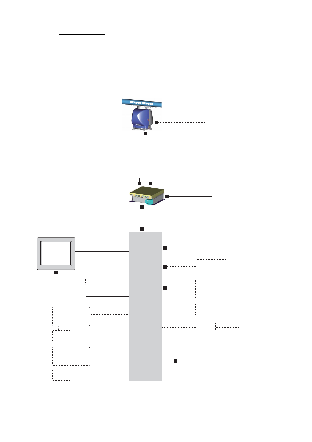
Standard wiring
A Cat 5e LAN cable (RW-00135) connects between the antenna unit and the PSU.
The maximum length of the cabling between the Processor Unit and the antenna unit
is 80 m.
Retrofit (using antenna cable RW-4873/6896/9600) or foremast installation is also
possible, with the installation of a pair of LAN Signal Converters, one in the antenna
unit, the other in the PSU. See section 2.7.
Antenna Unit
100-115/220-230 VAC
De-icer
DPYCY-1.5
RW-00135
15/30/40/50 m
RW-00136
15/30/40/50 m
Sub monitor
MU-190
(for FAR-3210/3220)
MU-231
(for FAR-3310/3320)
Monitor
Unit
100-230 VAC
100-115/
100-230 VAC
Radar
Control Unit
RCU-025
USB
memory
Power Supply Unit
PSU-014
Serial: TTYCS-1Q
DVI-D/D SINGLE LINK
5 m/10 m
DSUB9P-DSUB9P
5 m/10 m
VDR
IEC60320-C13-L5M
RGB cable
30 m
5 m
(for USB)
LAN Power
LAN: DTI-C5E 350 VCV
Cat 5e LAN cable
Processor Unit
EC-3000
DTI-C5E 350 VCV
DPYC-2.5
(10/20/30 m)
or
(local supply)
TTYCS-4
TTYCS-1Q
TTYCS-10
FR-FTPC-CY
(10/20/30 m)
100-230 VAC
GYRO, AIS
GPS, LOG, E/S,
WIND, ALARM,
NAVTEX, etc.
System fail, Power fail,
Normal close 1/2,
Normal open 1/2,
ACK IN
Sensor Adapter
or HUB-100
HUB-3000
x2
x5
DPYC-1.5
100-230 VAC
2-2
Trackball
Control Unit
RCU-026
USB
memory
x2
30 m
5 m
(for USB)
: Cable requires fabrication
2.2 Antenna Unit
Shield
390
Sheath
Coaxial
cable
400
400
Sheath
3
9
0
330
4
5
0
Three cables are connected to the antenna unit: antenna cable, cable for the sub monitor (option) and power cable for the deicer (option). The procedure shows how to connect all cables. Disregard the descriptions for the optional equipment if not applicable.
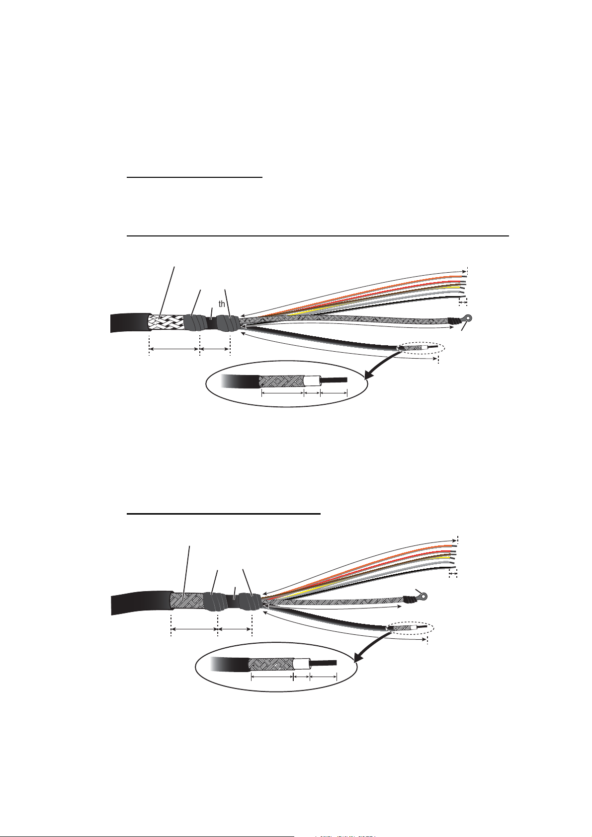
2.2.1 How to fabricate the cables
Antenna cable RW-00135
The end of the antenna cable RW-00135 which connects to the antenna unit is prefabricated.
Antenna cable RW-9600/6895/4873 (for retrofit or foremast installation)
Armor (clamp with cable clamp.)
2. WIRING
Sheath
Vinyl tape
Sheath
36 5
14
5
400
9
400
390
6
Shield
Crimp-on lug
Coaxial
cable
RW-9600 (foremast or retrofit):The white, red, and green wires are not used. Attach
a single crimp-on lug (FV5.5-S4(LF), yellow) locally to the wires. (These wires will be
connected together with the shield of the power line, in the next section.)
RW-6895/4873 (retrofit only): Fifteen wires are not used. Cut the wires and bind them
with vinyl tape. Do not connect the wires to ground.
Cable RW-00136 (for a sub monitor)
Armor (clamp with cable clamp.)
0
Sheath
36
Vinyl tape
Shield
5
330
3
5
4
Crimp-on lug
9
0
6
Braided shield
Coaxial cable
14
9
5
2-3
2. WIRING
Sheath
Sheath
Cable DPYCY-1.5 (for the optional deicer)
36
Sheath
10
Vinyl tape
Sheath
Armor
Lay armor in
cable clamp.
2.2.2 How to connect the cables
NOTICE
If there is a chance of inclement
weather when the transceiver unit is
removed, cover the intake on both
covers with packing tape. Be sure to
remove the tape after completing the
installation.
900
Wrap spiral tubing.
Intake
6
Crimp-on lug
(FV2-M4)
Some parts or wiring have been omitted from the illustrations for clarity.
1. Unfasten four bolts from the rear cover to remove the rear cover. If the deicer is
already installed or will be installed, remove two bolts inside the antenna to enable
removal of the front cover. See Note 2.
Note 1: The cable for the performance monitor is connected between the rear
cover and the RF-TB Board in the antenna unit. Open the cover slowly to prevent
damage to the cable and connector.
Note 2: If the deicer is to be installed, spread open the right and left heater elements on the cover, then remove the front cover, being careful not to hit the elements on the radiator or chassis.
Note 3: If this a retrofit or foremast installation, a LAN Signal Converter is required, in both the antenna unit and the power supply unit. See section 2.7.
2-4
2. WIRING
J803
(motor)
J808
(motor)
J804 (motor)
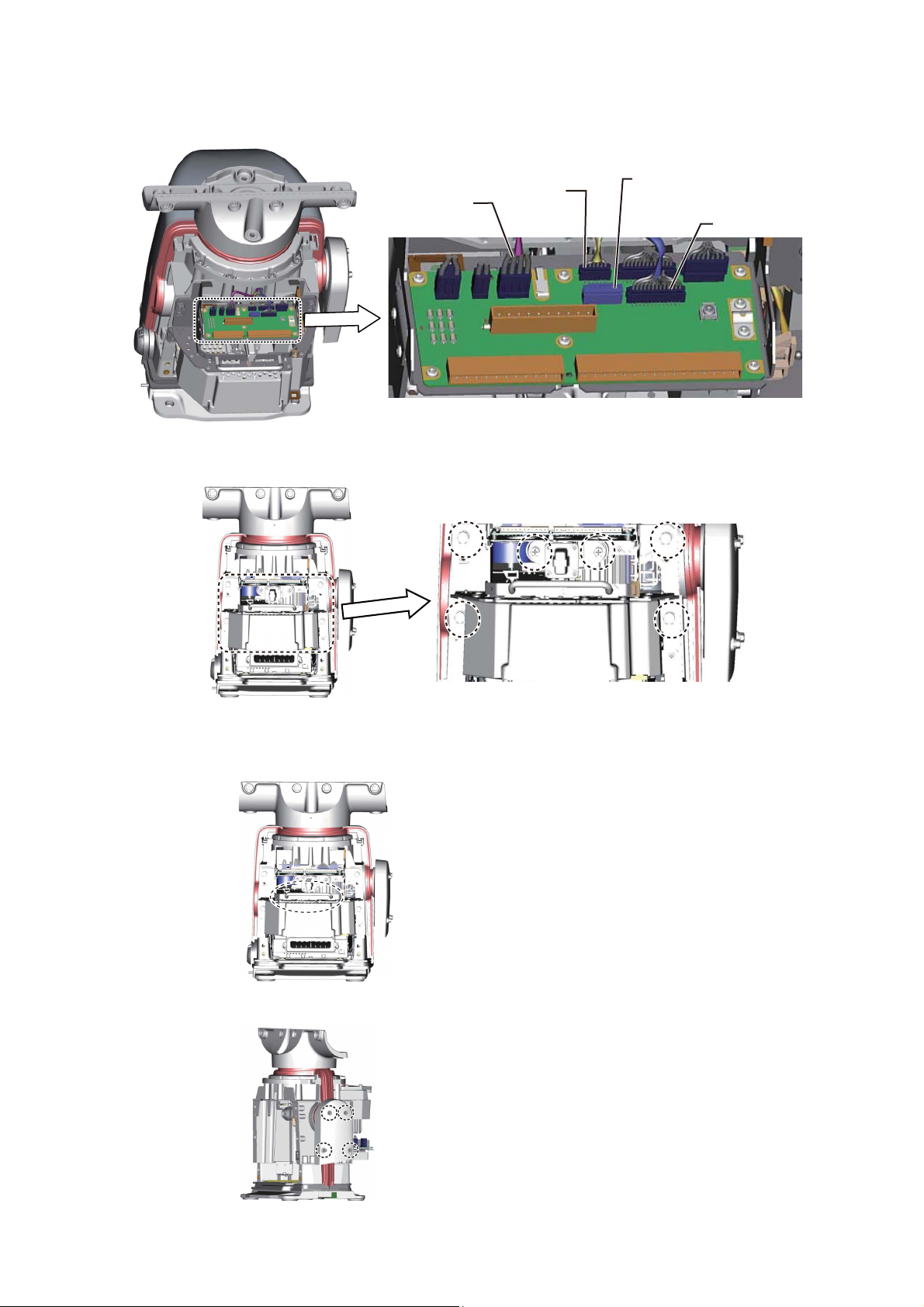
2. Disconnect the performance monitor connector (J807) and the motor drive connectors (J803, J804 and J808) from the RF-TB Board.
J807
(performance monitor)
J804 (motor)
J803
(motor)
J808
(motor)
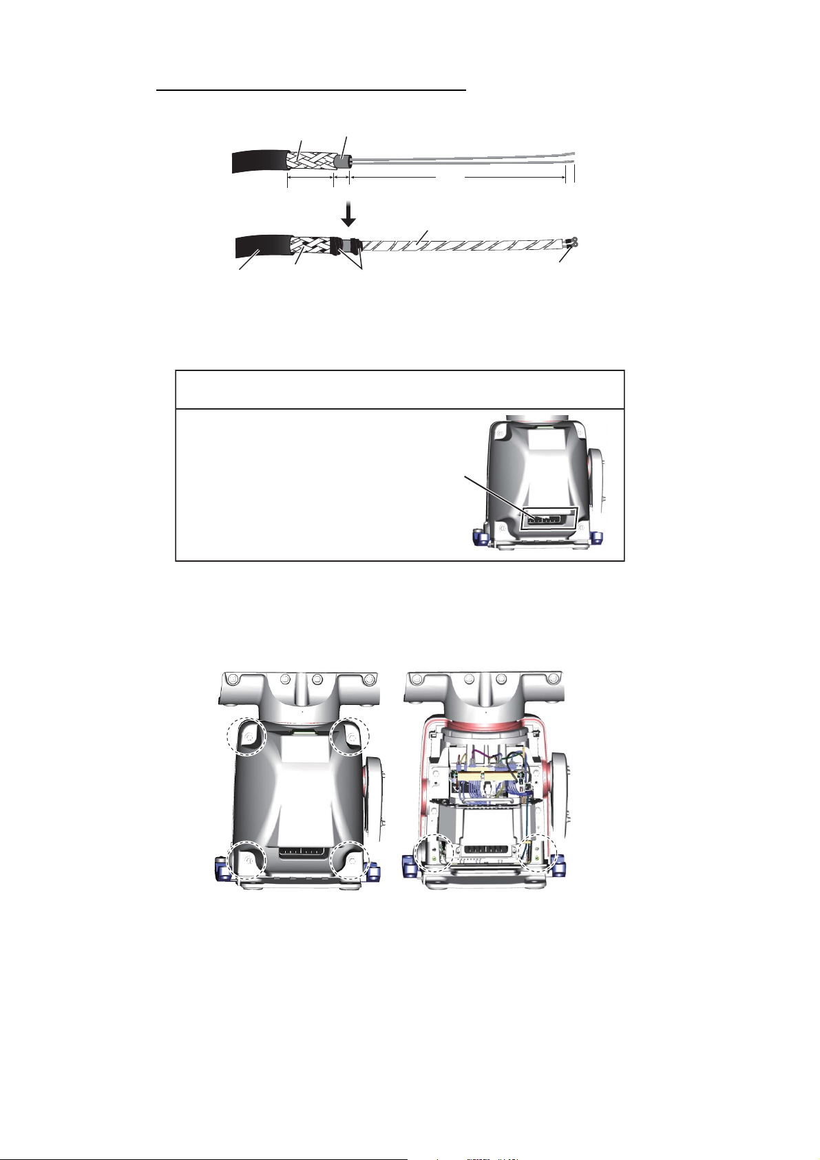
3. Unfasten the six bolts circled in the figure below to enable removal of the transceiver unit.
4. Pull the handle on the transceiver unit to remove the unit. Lay the unit on its side
or on top of non-ferrous material, to prevent demagnetization of the magnetron.
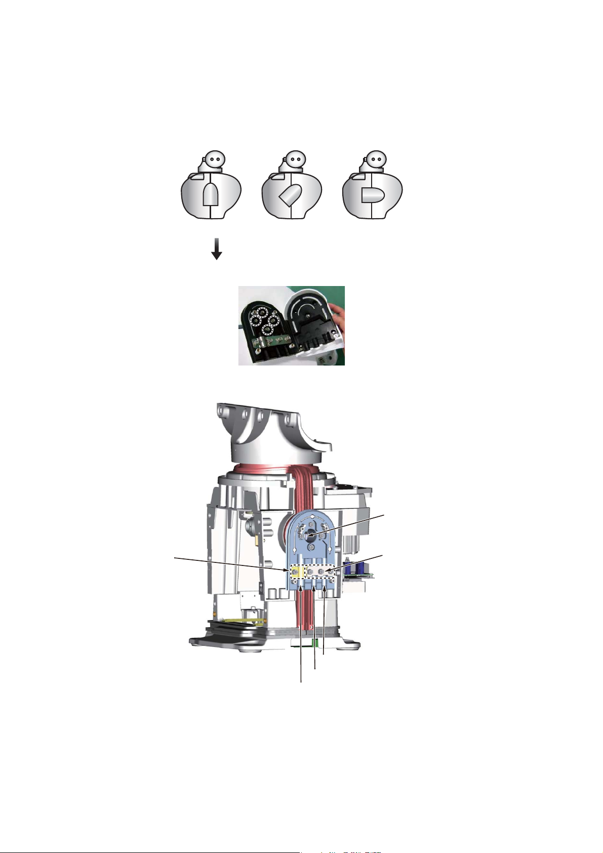
5. Unfasten four screws to open the cable entrance cover.
2-5
2. WIRING
Note: The orientation of the cable entrance assy. can be changed, in one of the
three orientations shown in the figure below. No other orientation is allowed, to
maintain watertight integrity. The default orientation is “deck”. To change the
entrance, unfasten the four screws circled in the figure below, then orient the cable entrance assy. in the required direction. Refasten the screws.
BOW ►
Deck entrance Mid-stern entrance Stern entrance
TO CHANGE THE ORIENTATION:
Unfasten these screws to change the orientation of the cable entrance assy.
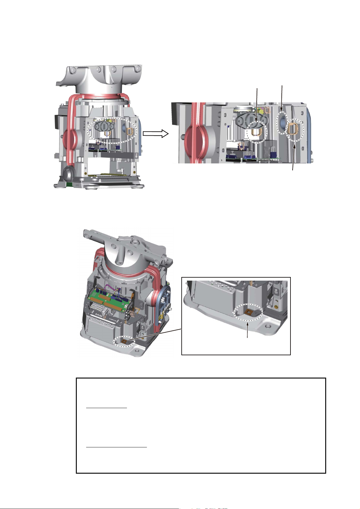
6. Unfasten the four screws fixing the cable clamp plates (2 pcs.).
Cable entrance
Cable clamp
plate for
antenna cable
Cable for sub monitor
Cable for deicer
Antenna cable
Cable clamp plate
for cable for sub
monitor, deicer
2-6
2. WIRING
7. Pass the antenna cable through the cable entrance. If applicable, also pass the
cable for the sub monitor and the power cable for the deicer through the cable entrance. Pass the cables through their respective locking wire saddles.
Locking wire saddle
for power cable for
deicer
Cable entrance
Locking wire saddle
for antenna cable,
cable for sub montior
8. Re-mount the transceiver unit then reconnect the connectors for the motor (J803,
J804 and J808). Pass the LAN cable through the locking wire saddle at the bottom
of the transceiver unit.
Locking wire saddle
for LAN cable
9. Connect the antenna cable and the cable for the sub monitor as shown below. See
the illustration on the next page for parts location.
• Attach appropriate WAGO connector (supplied) to both the antenna cable and the cable for the sub monitor. Connect the antenna cable and the cable for the sub monitor
to the RF-TB Board as shown below.
Antenna cable
Power line: TB801
LAN cable: J821
Shield of power line: Screw on fixing plate. See *
1
in illustration on next page.
Shield of LAN cable: Screw above LAN cable port.
Cable for sub monitor
Signal line: TB803
Shield: Screw on fixing plate. See *
2
in illustration on next page.
Coaxial cable: TB804
2-7
 Loading...