

Furuno USA 9ZWRTR090, 9ZWRTR093, 9ZWRTR095, 9ZWRTR091 Users Manual
Chapter 4: ARPA Operation
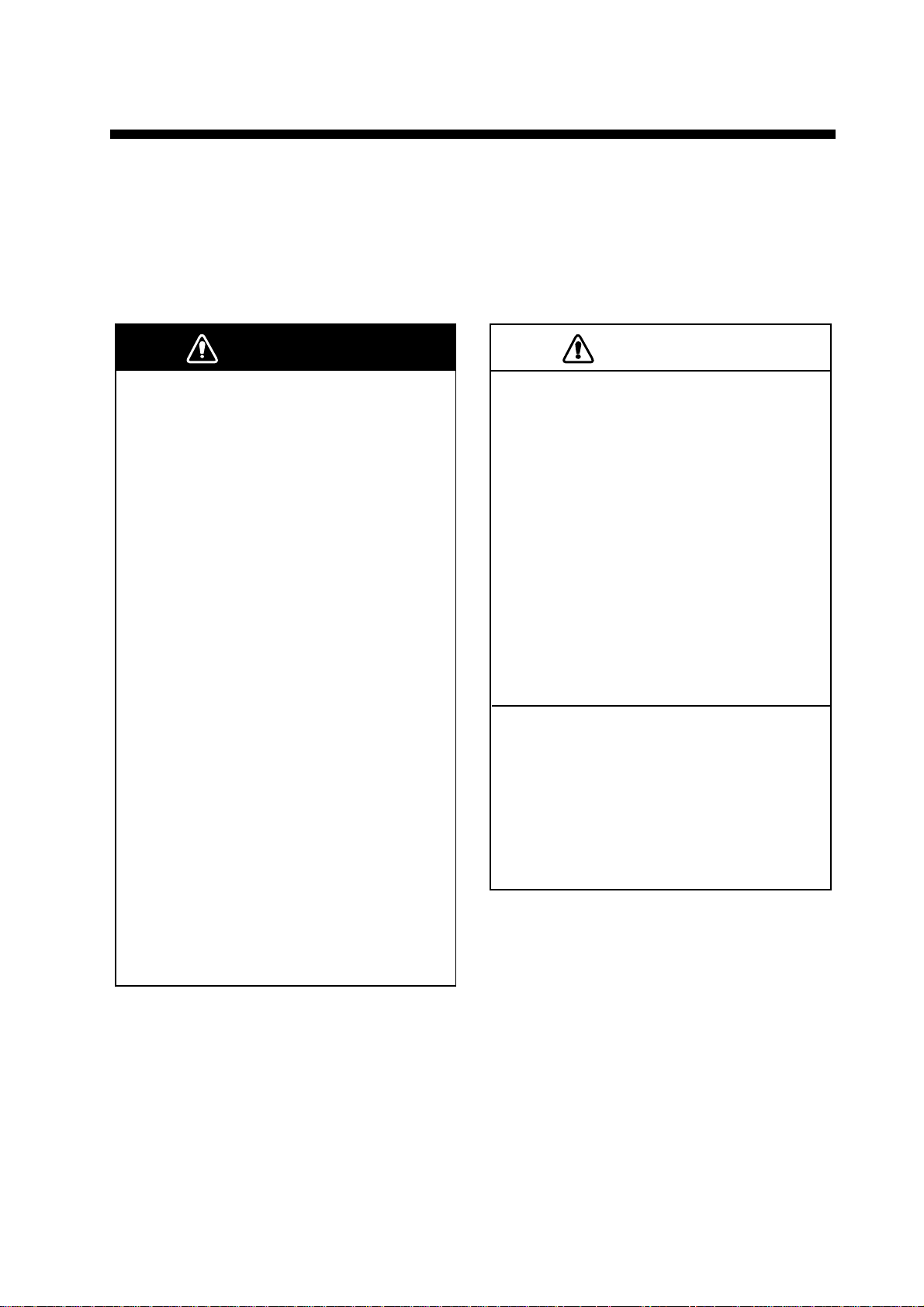
WARNING
CAUTION
This Automatic Radar Plotting Aid (ARPA) tracks the movement of up to 30 radar targets. Targets can be acquired manually or automatically. All 30 targets can be acquired manually when the ARPA acquisition area is inactive. With the acquisition area
that total is equally divided between manual and auto acquisition.
ARPA requires speed and heading data. The symbols used in this radar comply with
IEC 60872-1.
No one navigational aid should be relied
upon for the safety of vessel and crew.
The navigator has the responsibility to
check all aids available to confirm
position. Electronic aids are not
a substitute for basic navigational
principles and common sense.
• This auto plotter automatically tracks an
automatically or manually acquired radar
target and calculates its course and
speed, indicating them by a vector. Since
the data generated by the auto plotter
are based on what radar targets are
selected, the radar must always be
optimally tuned for use with the auto
plotter, to ensure required targets will not
be lost or unwanted targets such as sea
returns and noise will not be acquired
and tracked.
• A target does not always mean a land mass, reef, ships or other surface vessels
but can imply returns from sea surface
and clutter. As the level of clutter changes
with environment, the operator should
properly adjust the A/C SEA, A/C RAIN
and GAIN controls to be sure target
echoes are not eliminated from the
radar screen.
The plotting accuracy and response of
this auto plotter meets IMO standards.
Tracking accuracy is affected by the
following:
• Tracking accuracy is affected by course
change. One to two minutes is required to
restore vectors to full accuracy after an
abrupt course change. (The actual
amount depends on gyrocompass
specifications.)
• The amount of tracking delay is inversely
proportional to the relative speed of the
target. Delay is on the order of 15–30
seconds for high relative speed; 30–60
seconds for low relative speed.
Display accuracy is affected by the
following:
• Echo intensity
• Radar transmission pulsewidth
• Radar bearing error
• Gyrocompass error
• Course change (own ship or target)
4-1
Chapter 4: ARPA Operation
4.1 Enabling, Disabling ARPA
1. On the Chart Plotter or Radar display, long-push the Rotary Knob.
2. Select the Targets ROTOkey and push the Rotary Knob.
3. Select the ARPA ROTOkey.
4. Push the Rotary Knob to alternately enable and disable the ARPA display.
4.2 Manually Acquiring a Target
1. Use the Cursorpad to put the cursor on the target you want to acquire.
2. Press the right-button key to show the Radar pop-up menu.
3. Select Acquire Target and push the Rotary Knob.
A target just acquired is marked with a broken square and a vector appears within 20
scans of the antenna to indicate the target's motion trend. Within 60 scans, the initial
tracking stage is finished and the target becomes ready for stable tracking. At this
point, the broken square mark changes to a solid circle. (Targets automatically acquired are distinguished from those acquired manually. The targets which are acquired manually are displayed by bold symbol.)
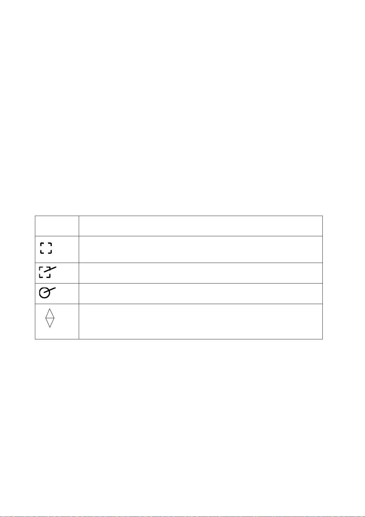
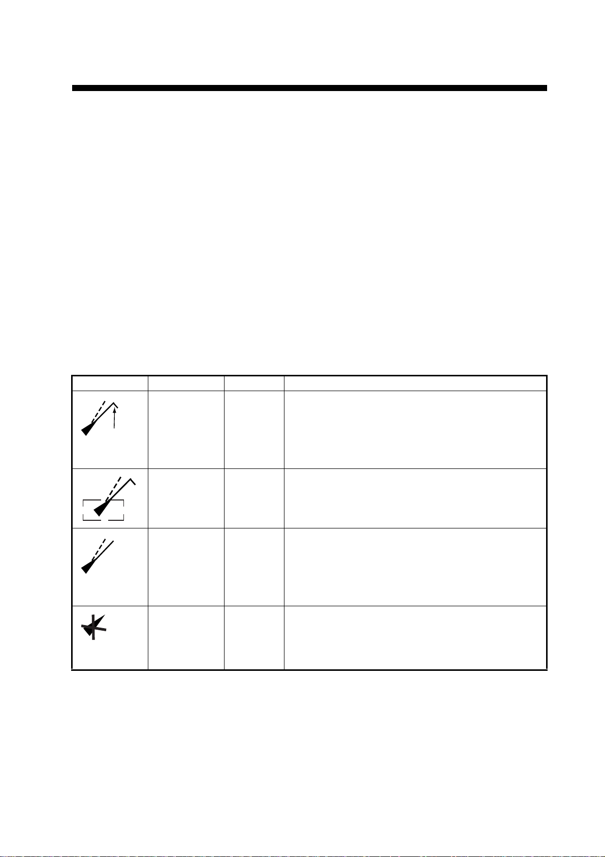
ARPA
Symbol
(flashing)
Meaning
Immediately after acquisition.
Within 20 scans of the antenna after acquisition, a vector appears to show a trend
of movement.
Within 60 scans of the antenna after acquisition, the plotting symbol changes to a
small circle, indicating steady-state tracking condition.
Lost target is indicated by flashing diamond symbol. The diamond is formed from
two equal triangles.
Note 1: For successful acquisition, the target to be acquired should be within 0.2 to
32 nm from own ship and not obscured by sea or rain clutter.
Note 2: When the capacity for manual acquisition is reached, an appropriate message
appears in the text message area. Cancel tracking of non-threatening targets if you
wish to acquire additional targets manually.
Note 3: Acquisition is also possible with the ROTOkeys. Select the target to acquire,
long-push the Rotary Knob, choose the Target ROTOkey followed by the Acquire ROTOkey.
4.3 Clearing a Lost Target
On the radar or chart plotter display, place the cursor on the lost target and select the
ROTOkeys Target and Clear Lost.
4-2

4.4 Cancelling Tracking of Targets
ARPA targets can be cancelled individually or collectively as shown below. All targets
can also be cancelled from the Radar pop-up menu.
1. For cancelling individual target, use the Cursorpad to put the cursor on the tar-
get you want to cancel tracking.
2. Long-push the Rotary Knob.
3. Select the Targets ROTOkey and push the Rotary Knob.
4. Select the Cancel or Cancel All ROTOkey as applicable and push the Rotary
Knob.
Tracking is cancelled and targets are erased from the screen.
4.5 CPA/TCPA Alarm
The CPA/TCPA alarm is useful for alerting to possible collision situations. With the
alarm active, the ARPA continuously monitors the predicted range at the Closest Point
of Approach (CPA) and predicted time to CPA (TCPA) of each tracked target to own
ship. When the predicted CPA of any target becomes smaller than a preset CPA alarm
range and its predicted TCPA less than a preset TCPA alarm limit, the buzzer sounds
and an appropriate text message appears. In addition, the ARPA symbol changes to
a triangle and flashes together with its vector.
Chapter 4: ARPA Operation
Provided that this feature is used correctly, it will help prevent the risk of collision by
alerting you to threatening targets. However, it is important that gain, sea and rain controls are properly adjusted.
CPA/TCPA alarm ranges must be set up properly taking into consideration the size,
tonnage, speed, turning performance and other characteristics of own ship.
Setting the CPA/TCPA Alarm
1. Press the MENU key to open the menu.
2. Select the Radar sub menu.
3. Select CPA/TCPA Alarm.
4. Push the Rotary Knob to show the status box in green to activate the CPA/TCPA
alarm.
5. Set CPA and TPCA values at CPA Alarm Value and TCPA Alarm Value.
6. Press the MENU key to close the menu.
Acknowledging the CPA/TCPA Alarm
The CPA/TCPA alarm sounds when the CPA and/or TCPA of an ARPA target is within
the CPA/TCPA alarm range. To acknowledge and silence the CPA/TCPA alarm,
press the CANCEL key. The audio alarm is silenced and the symbol stops flashing.
Disabling the CPA/TCPA Alarm
Show the status box of CPA/TCPA Alarm in gray to disable the alarm. (See "Setting
the CPA/TCPA Alarm" above for the procedure.)
4-3
Chapter 4: ARPA Operation
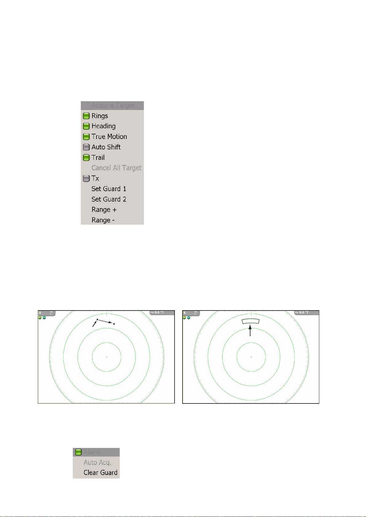
4.6 Setting ARPA Acquisition Area
Any target entering the ARPA acquisition area will be automatically acquired and
tracked. When a target transits the area, the buzzer sounds and the target causing the
warning is clearly indicated with an inverted flashing triangle. You can silence the
buzzer with the CANCEL key.
1. On the radar display, push the right-button key to show the Radar pop-up menu.
2. Rotate the Rotary Knob to choose Set Guard 1 or Set Guard 2, whichever you
want to set, and push the Rotary Knob. The point placement cursor appears at
cursor location.
3. Use the Cursorpad to put the point placement cursor at the top left corner for the
guard zone (Point A below).
4. Press the left-button key in the center of the Cursorpad.
5. Use the Cursorpad to drag the point placement cursor to the bottom right corner
(Point B below) for the guard zone and push the left-button key.
Point A
Drag cursor to Point B
Point B
Acquisition Area
4-4
To erase the guard zone (and return to full manual acquisition), put the cursor on
a line of the guard zone and push the right-button key to show the Guard Zone popup. (The line becomes thicker if correctly selected.) Rotate the Rotary Knob to choose
Clear Guard and push the Rotary Knob.
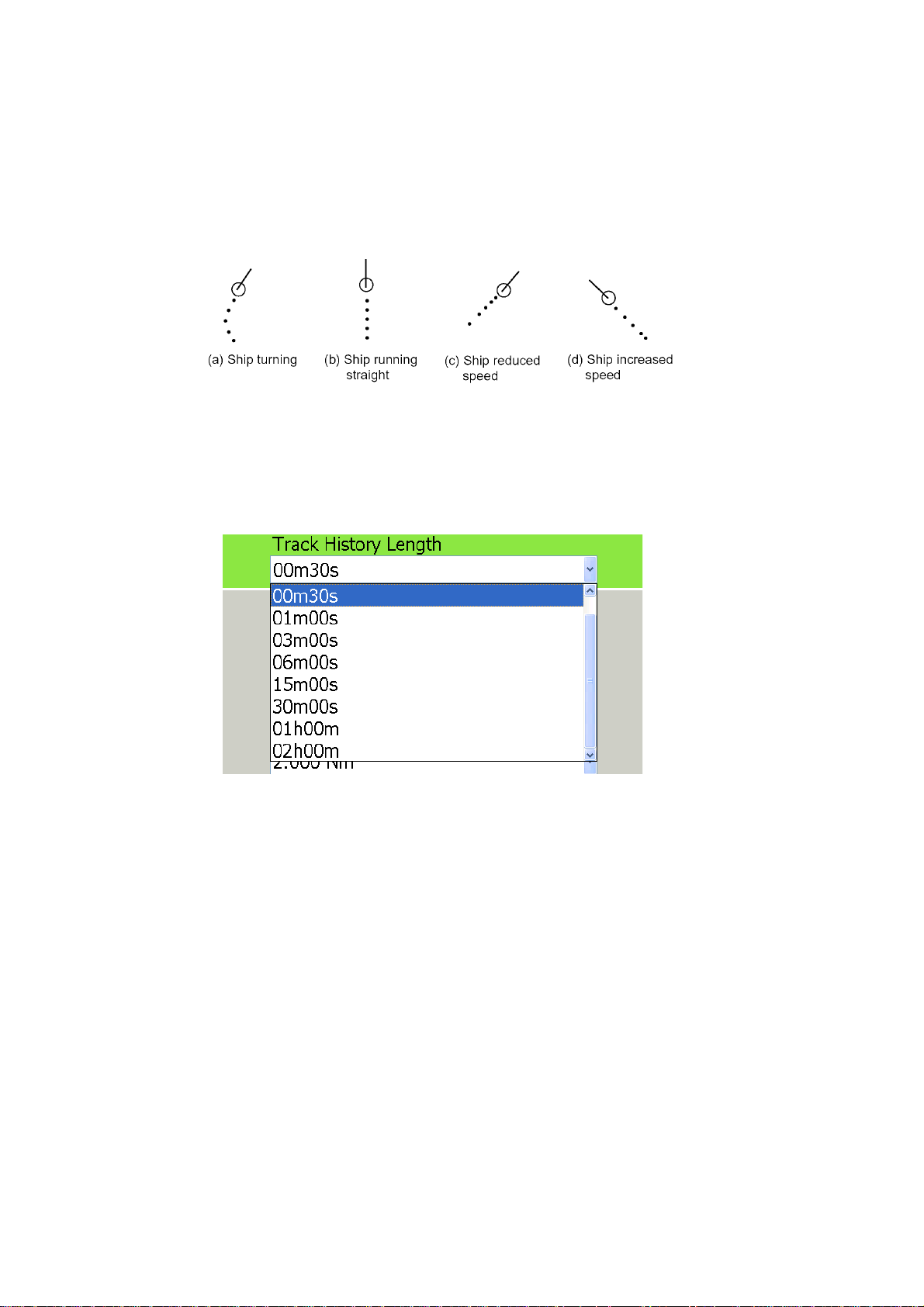
4.7 Track History Display
This ARPA can mark the past positions of any targets being tracked, with equally timespaced dots.
A new dot is added every minute (or at other preset time intervals) until the preset
number is reached. If a target changes its speed, the spacing between dots will be uneven. If a target changes its course, its plotted course will not be a straight line.
Selecting Track History Plotting Interval
1. Press the MENU key to open the menu.
2. Open the Targets menu.
Chapter 4: ARPA Operation
3. Select Track History Length and push the Rotary Knob.
4. Rotate the Rotary Knob to select plot interval desired.
5. Press the MENU key to close the menu.
Showing, Hiding the Track History Display
On the radar display or the chart plotter display, long-push the Rotary Knob to show
the ROTOkeys. Choose the Targets ROTOkey followed by the Track ROTOkey. Push
the Rotary Knob to alternately show and hide the track history display.
4-5
Chapter 4: ARPA Operation
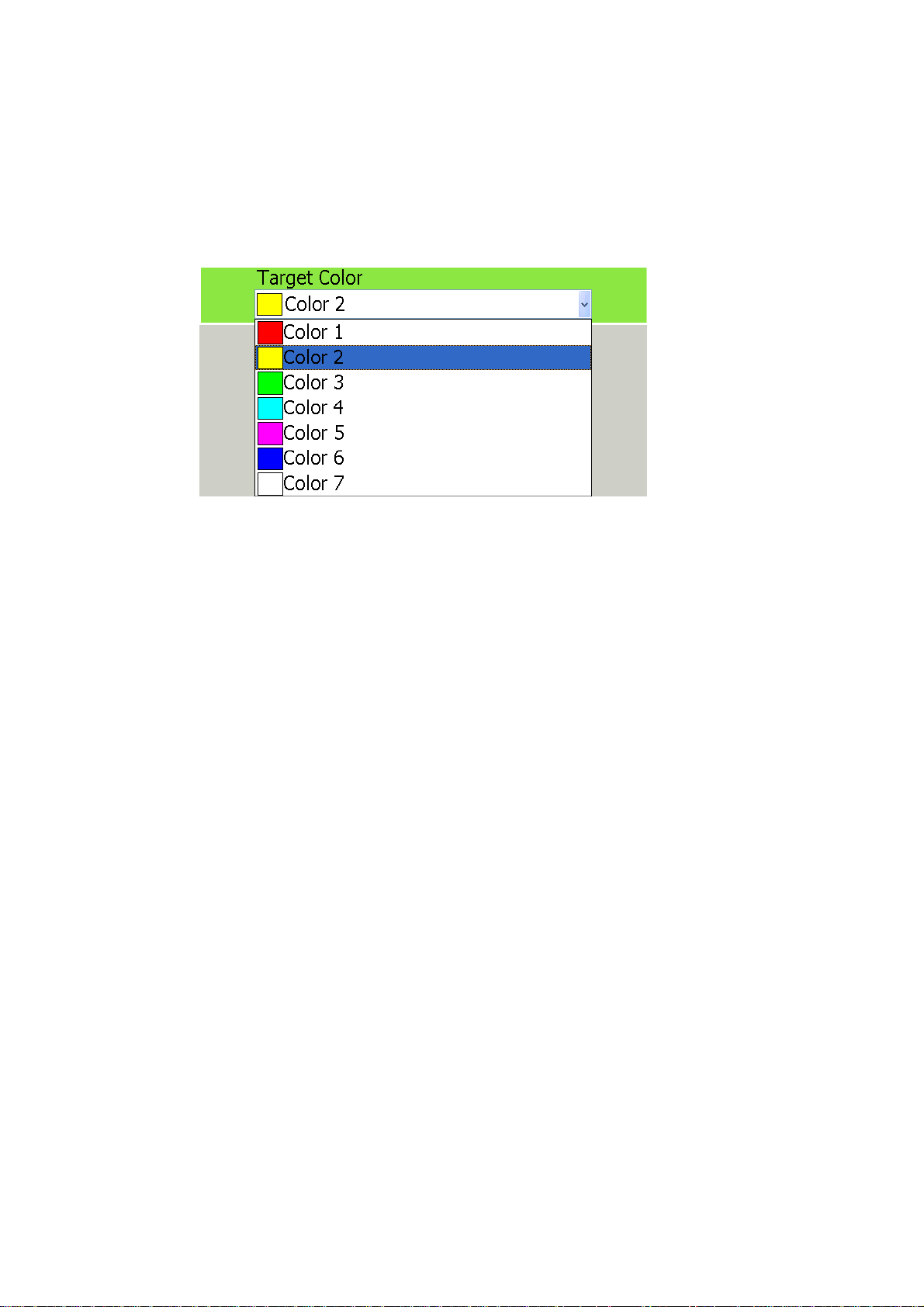
4.8 ARPA Symbol Color
The color of the ARPA symbol is available in yellow, red, green, light-blue, purple,
blue, and white.
1. Press the MENU key to open the menu.
2. Open the Targets menu.
3. Select Target Color and push the Rotary Knob.
4. Select color desired and push the Rotary Knob.
5. Press the MENU key to close the menu.
4-6
Chapter 5: AIS Operation
An AIS transponder uses VHF frequencies, and broadcasts your own vessel's position, name, callsign, along with detailed parameters like length, beam, draft, and tonnage. It also broadcasts details of the current navigation system: speed, course, rate
of turn, destination, and ETA. The transponder receives this same information from
other ships, and displays it on radar and chart plotter displays. The positions and intentions of nearby vessels are available to you unambiguously and in real time.
5.1 Enabling, Disabling AIS
1. Long-push the Rotary Knob to show the ROTOkeys.
2. Select the Targets ROTOkey and push the RotaryKnob.
3. Select AIS and push the Rotary Knob to alternately turn the AIS function on and
off.
5.2 AIS Target Symbols
Symbol Target type Color Description
Activated
target w/ROT
line
ROT line
Ta rg et
selected
Dangerous
target
Lost target
Blue Heading is shown with a solid line extending from the
tip of the triangle. COG is shown with a broken line
extending from the center of the triangle. The ROT line
appears when a target's ROT is more than 10
degrees/min.
Blue A target selected to display its data is marked with a
broken rectangle.
Red An AIS target whose CPA and TCPA are less than
those values set on the CPA Settings dialog box or the
proximity alarm range is considered a dangerous target, on collision course with own ship. A dangerous
target is colored pink when selected to find its data.
Black or
white
If no signal is received from an AIS target for 10
minutes it is declared a lost target. If no signal is
received for another 10 minutes the lost target
symbol is automatically erased.
5-1
Chapter 5: AIS Operation
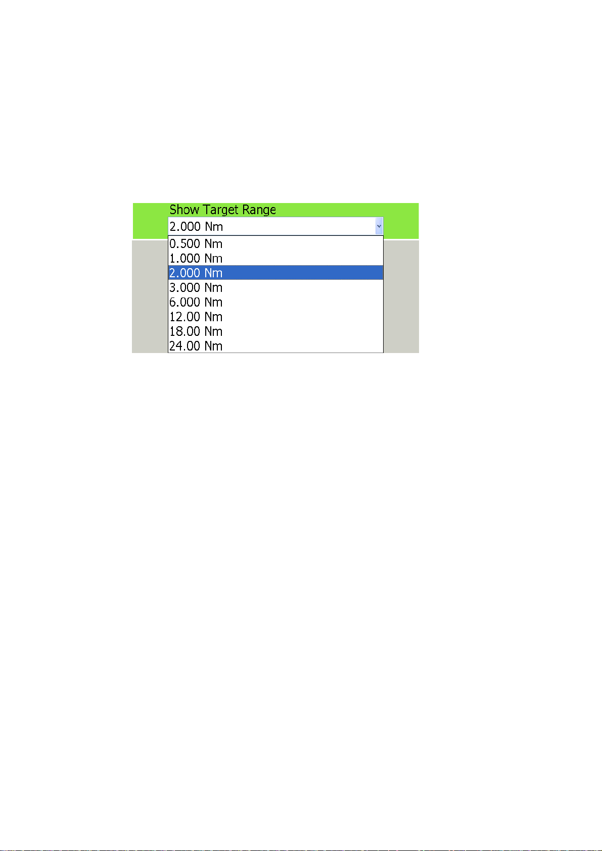
5.3 Setting Acquisition Range
In the default setting, all AIS targets within VHF range from your boat are shown on
the display. If the screen becomes too cluttered with AIS targets, you may wish to set
an acquisition range in order lessen the number of AIS targets on the screen. Only
those targets within the range selected will be monitored.
1. Press the MENU key to open the menu.
2. Open the Targets menu.
3. Select Show Target Range and push the RotaryKnob.
4. Select a range and push the Rotary Knob.
5. Press the MENU key to close the menu.
5-2

5.4 Track History Display
This AIS can mark the past positions of any targets being tracked, with equally timespaced dots.
A new dot is added every minute (or at other preset time intervals) until the preset
number is reached. If a target changes its speed, the spacing between dots will be uneven. If a target changes its course, its plotted course will not be a straight line.
Selecting Track History Plotting Interval
1. Press the MENU key to open the menu.
2. Open the Targets menu.
Chapter 5: AIS Operation
3. Select Track History Length and push the RotaryKnob.
4. Rotate the Rotary Knob to select plot interval desired.
5. Press the MENU key to close the menu.
Showing, Hiding the Track History Display
On the radar display or the chart plotter display, long-push the Rotary Knob to show
the ROTOkeys. Choose the Targets ROTOkey followed by the Track ROTOkey. Push
the Rotary Knob to alternately show and hide the track history display.
5-3

Chapter 5: AIS Operation
5.5 Showing, Hiding Target ID
The MMSI no. of an AIS target can be shown or hidden on the display.
1. Press the MENU key to open the menu.
2. Open the Targets menu.
3. Select DIsplay Target IDs.
4. Push the Rotary Knob to alternately show and hide the target IDs.
5. Press the MENU key to close the menu.
5-4

Chapter 6: Card Operations
This chapter covers how to use SD cards to save and load data, and how to manage
your chart cards. Topics include
• Save tracks, routes and points
• Load tracks, routes and points
• Save user setup
• Load user setup
• Manage chart catalog
• Delete files
• Move files, and
• Request and load update files
6.1 Compatible SD Cards
The manufacturer and model of compatible SD cards are listed in the table below
Compatible SD cards
Make Model Capacity
SANDISK SDSDB-xxx-J60
DSDH-xxx-903
Panasonic RP-SDRxxxJ1A/
RP-SDKxxxJ1A
RP-SDxxxBL1A
Lexar: SDxxx-231
PQI QSDS-xxx 256 MB, 512 MB, 1 GB, 2 GB
Kingston SD/xxxFE 256 MB, 512 MB, 1 GB, 2 GB
I/O DATA SD-xxx 128 MB, 256 MB, 512 MB, 1 GB, 2 GB
SDP-xxx 256 MB, 512 MB, 1 GB, 2 GB
HAGIWARA
SYS-COM
PC-SDxxxM 256 MB
PC-SDxxxTP 256 MB, 512 MB, 1 GB
256 MB, 512 MB, 1 GB, 2GB
512 MB, 1 GB, 2GB
512 MB, 1 GB, 2 GB
256 MB
256 MB, 512 MB, 1 GB
HPC-SDxxxM2 128 MB, 1 GB, 2GB
HPC-SDxxxT 128 MB, 256 MB, 512 MB, 1 GB, 2 GB
BUFFALO
xxx: Capacity of card
RSDC-Sxxx 32 MB, 64 MB, 128 MB, 256 MB, 512 MB, 1 GB, 2 GB
RSDC-Gxxx 512 MB, 1 GB, 2 GB
6-1
Chapter 6: Card Operations
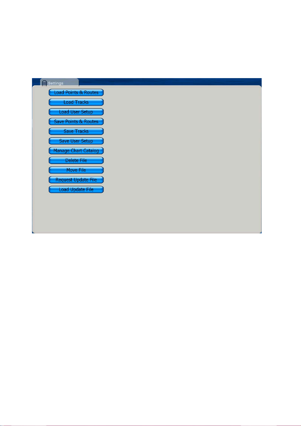
6.2 Saving and Loading Data
The Save & Load menu is where all phases of saving and loading are done. To display
the Save & Load menu, do the following:
1. Press the MENU key to open the menu.
2. Rotate the Rotary Knob to choose Save & Load and push the Rotary Knob.
Saving Data
Save Points & Routes
This unit holds 2,000 points and 200 routes in its hard disk. When the capacity for
points or routes is reached, a new point or route cannot be entered unless an unnecessary one is erased. For those reasons, you may wish to save points and routes to
an SD card. Select Save Points & Routes from the Save and Load menu to save points
and routes. Follow the on-screen instructions.
Save Tracks
The hard disk of this unit holds 12,000 points of tracks. When that total is reached, the
oldest track is deleted to make room for the latest. If you require the track save it to an
SD card. Select Save Tracks and follow the on-screen instructions.
6-2

Chapter 6: Card Operations
Save User Setup
The user setup feature stores all user-set menu options. It may be useful to have several different sets of user setups to set up the system according to expected usage.
For example, you may want to have a user setup with settings suited to fishing and
one for cruising. Select Save User Setup and follow the on-screen instructions.
Loading Data
Load Points and Routes
Use the Load Points and Routes function to load points and routes saved to an SD
card. Points and routes loaded from an SD card are displayed together with current
points and routes. In case of identical names, the point or route data is written over
with the matching data on the SD card. Select Load Points & Routes and follow the
on-screen instructions.
Load Tracks
You can load past tracks on the display. This is useful when you want to created a
route using past tracks. Select Load Tracks and follow the on-screen instructions.
Load User Setup
Select Load User Setup to load user settings into the HD. The current user settings
are written over. Select Load User Setup and follow the on-screen instructions.
Deleting Files
Select Delete File and follow on-screen instructions to delete files.
Moving Files
Select Move File to copy MP3 files, etc.
Manage Chart Catalog
Use this feature to delete and transfer (to SD card) the charts stored on the hard disk.
Request Update File
This feature requests the application version nos. of all NavNet equipment in the NavNet network.
Load Update File
Select this item to update all NavNet applications in the NavNet network.
6-3

Chapter 6: Card Operations
This page is intentionally left blank.
6-4

Chapter 7: Customizing Your Unit
After you have become familiar with your equipment’s basic operating procedures,
you will need to
• set it up according to equipment connected to it, and
• tailor how it operates and displays information
All tailoring is done from the menu, which is opened and closed with the MENU key.
Once you have set the values, they are retained in the processor, even when the system is powered off. If you decide to return to default settings, a convenient, "Set Default" button is provided on each sub menu to quickly restore all default settings for the
the selected sub menu.
A few of the items which you can customize are
• ROTOkeys
• NavData boxes
• units of measurement
• general settings
• system settings, and
• chart display
7-1

Chapter 7: Customizing Your Unit
7.1 ROTOkeys
The user can select how many ROTOkeys to make available with the Rotary Knob.
Three pre-set amounts are available: basic, standard and full. A custom setting is also
available, and it allows you to select the ROTOkeys to make available.
The ROTOkeys available with the basic, standard and full sets in the chart plotter and
radar modes are shown in the tables on the next several pages.
Chart plotter ROTOkey description and ROTOkey availability
Basic Standard Full Title Level 1 Function
Yes Yes Yes North-Up
Yes Yes Yes Course Up
Yes Yes Yes Head Up
No No Yes Auto Shift Autoshift on/off
No Yes Ye s 3D 3D 3D/2D display selection
No Yes Yes 2D 2D view
No Yes Yes 3D Mariner Mariner 3D view
No No Yes 3D Custom last user "oriented" view
No No Yes Orientation 3D display orientation tool
Yes Yes Yes Track Show/hide track
No Yes Ye s Radar Radar Overlay
No Yes Ye s Rings Show/hide
No No Yes Targets ARPA/AIS
No No Yes ARPA Show/hide ARPA display.
No No Yes AIS Show/hide AIS display.
No No Yes Track Show/hide track history display.
No No Yes Acquire Acquire target for ARPA.
No No Yes Cancel
No No Yes Cancel All
No No Yes Clear Lost
No Yes Ye s Points
No Yes Yes List Show Points list.
No Yes Yes Create Enter a point.
No No Yes Points Show/hide points.
No Yes Ye s Routes
No Yes Yes New Create new route.
No Yes Yes List Show Routes list.
No Yes Yes XTE Init Restart XTE.
No Yes Yes Stop Stop following a route.
No Yes Yes Reverse Reverse route following direction.
No No Yes Routes Show/hide routes.
Yes Yes Yes Chart Chart selection
Yes Yes Yes Raster Raster chart
Yes Yes Yes Vector Vector chart
Yes Yes Yes Photo Show/hide satellite photo.
Yes Yes Yes Display
No Yes Yes Shading Show/hide depth contours.
No Yes Yes Tide Show/hide tide display.
No Yes Yes Current Show/hide tidal currents.
No No Yes Weather Show/hide weather display.
No No Yes Animate Animate Animate weather/tidal current.
Yes Yes Yes Tide Tide Show/hide tide display.
No No Yes Entertain Entertain Enable/disable entertainment.
No Yes Ye s Ruler Ruler tool
North-up/Courseup/Head-up
on/off
range rings
Point processing
Route processing
Show/hide display
Presentation mode selection
Cancel tracking on selected ARPA target.
Cancel tracking on all ARPA targets.
Clear lost ARPA target.
Measure range/bearing to a location.
7-2

Chapter 7: Customizing Your Unit
Radar ROTOkey description and ROTOkey availability
Basic Standard Full Title Level1
No Yes Ye s North-Up North-up/Course-up/Head-up
No Yes Yes North Up
No Yes Yes Course Up
No Yes Ye s Hea d Up
No No Yes True motion True motion on/off
No No Yes Auto Shift Autoshift on/off
Yes Ye s Yes Tx Tx on/off
No No Yes Process. Radar image processing
No No Yes Int.Rej. Interference rejector on/off
No No Yes Stretch Echo stretch on/off
No No Yes Average Echo average on/off
Yes Ye s Yes Rings Range rings on/off
No Yes Ye s Heading Heading line on/off
No No Yes Trail Echo trail on/off
No No Yes Clear Trail Clear echo trails.
No Yes Ye s EBL EBL processing
No Yes Yes EBL1 Activate EBL1.
No No Yes EBL2 Activate EBL2.
No Yes Yes Clear1 Deactivate EBL1.
No No Yes Clear2 Deactivate EBL2.
No Yes Ye s VRM VRM processing
No Yes Yes VRM1 Activate VRM1.
No No Yes VRM2 Activate VRM2.
No Yes Yes Clear1 Deactivate VRM1.
No No Yes Clear2 Deactivate VRM2.
No No Yes Guard Guard Zone processing
No No Yes Zone1 Enable guard zone 1.
No No Yes Zone2 Enable guard zone 2.
No No Yes Clear1 Disable guard zone 1.
No No Yes Clear2 Disable guard zone 2.
No No Yes Watchman Enable, disable watchman.
No No Yes Targets ARPA/AIS target processing
No No Yes ARPA Show/hide ARPA display.
No No Yes AIS Show/hide AIS display.
No No Yes Track Show/hide track history display.
No No Yes Acquire Acquire target for ARPA.
No No Yes Cancel
No No Yes Cancel All Cancel tracking on all ARPA targets.
No No Yes Clear Lost Clear lost ARPA target.
No No Yes Routes Show/hide routes.
Yes Ye s Yes Tide Show/hide tide display.
No No Yes Entertain Enable, disable entertainment.
Cancel tracking on selected ARPA target.
7-3
 Loading...