

Furuno USA 9ZWRTR088A Users Manual

OPERATOR'S MANUAL
MARINE RADAR
MODEL
MODEL 1937
www.furuno.co.jp

Thepaperusedinthismanual
9‑52Ashihara‑cho,
Fax:
A:FEB
2009
.
C:JAN.18,2010
Pub.No.
(
)
*
00017123712
**00017123712
*
Nishinomiya,662‑8580,JAPAN
Telephone: +81‑(0)798‑65‑2111
+81‑(0)798‑65‑4200
iselementalchlorinefree.
・FURUNOAuthorizedDistributor/Dealer
Allrightsreserved.
YOTA
MODEL1937
PrintedinJapan
OME‑35820‑C
*00017123712**00017123712*
*00017123712*

IMPORTANT NOTICES
General
• This manual has been authored with simplified grammar, to meet the needs of international users.
• The operator of this equipment must read and follow the descriptions in this manual. Wrong operation or maintenance can cancel the warranty or cause injury.
• Do not copy any part of this manual without written permission from FURUNO.
• If this manual is lost or worn, contact your dealer about replacement.
• The contents of this manual and equipment specifications can change without notice.
• The example screens (or illustrations) shown in this manual can be different from the screens
you see on your display. The screens you see depend on your system configuration and equipment settings.
• Save this manual for future reference.
• Any modification of the equipment (including software) by persons not authorized by FURUNO
will cancel the warranty.
• All brand and product names are trademarks, registered trademarks or service marks of their
respective holders.
How to discard this product
Discard this product according to local regulations for the disposal of industrial waste. For disposal
in the USA, see the homepage of the Electronics Industries Alliance (http:// www.eiae.org/) for the
correct method of disposal.
How to discard a used battery
Some FURUNO products have a battery(ies). To see if your product has a battery(ies), see the
chapter on Maintenance. Follow the instructions below if a battery(ies) is used.
In the European Union
The crossed-out trash can symbol indicates that all types of batt eries
must not be discarded in standard trash, or at a trash site. Take the
used batteries to a battery collection site according to your national
legislation and the Batteries Directive 2006/66/EU.
In the USA
The Mobius loop symbol (three chasing arrows) indicates that Ni-Cd
and lead-acid rechargeable batteries must be recycled. Take the used
batteries to a battery collection site according to local laws.
Ni-Cd Pb
In the other countries
Cd
There are no international standards for the battery recycle symbol. The number of symbols can
increase when the other countries make their own recycle symbols in the future.
i
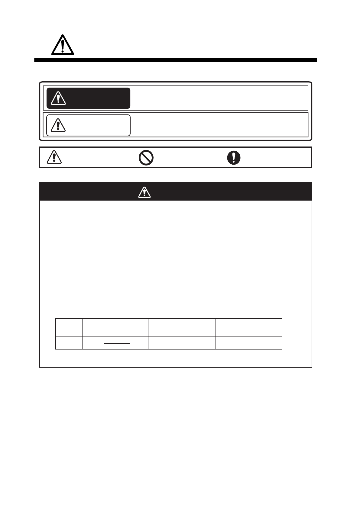
SAFETY INSTRUCTIONS
Read these safety instructions before you operate the equipment.
Indicates a condition that can cause death or serious
WARNING
CAUTION
injury if not avoided.
Indicates a condition that can cause minor or moderate
injury if not avoided.
Warning, Caution
Prohibitive Action
Mandatory Action
WARNING
Radio Frequency Radiation Hazard
The radar antenna sends the electromagnetic radio frequency (RF) energy. This
energy can be dangerous to you, especially your eyes. Do not look at the radiator or
near the antenna when the antenna is rotating.
2
The distances at which RF radiation levels of 100 W/m
are shown in the table.
Note: If the antenna unit is installed at a close distance in front of the wheel house,
prevent the transmission in that area to protect passengers and crew from microwave
radiation. Set the [Sector Blanks] in the [System] menu.
Model
Distance to
100 W/m
2
point
Distance to
50 W/m
2
point
,
50 W/m2 and 10 W/m2 exist
Distance to
10 W/m
2
point
1937
0.1 m
0.9 m
ii
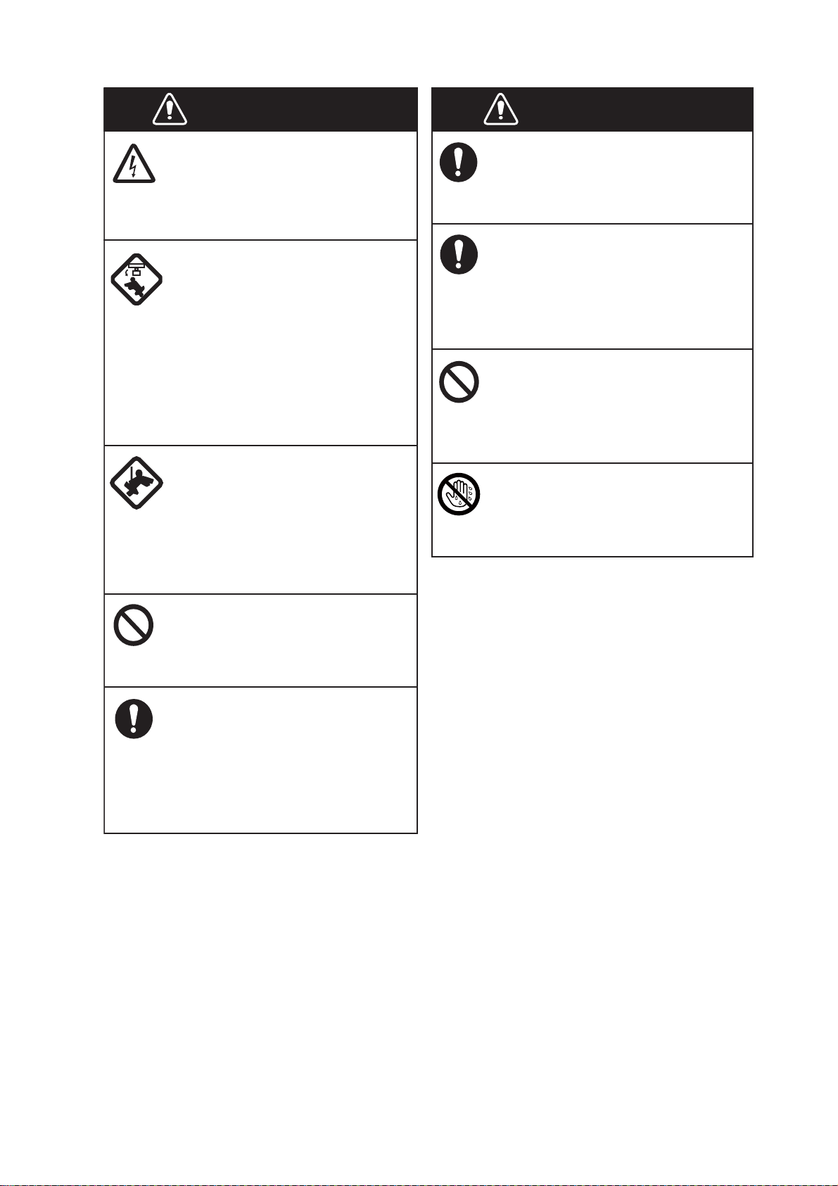
SAFETY INSTRUCTIONS
WARNING
ELECTRICAL SHOCK HAZARD
Do not open the equipment.
Only qualified persons can work
inside the equipment.
Turn off the power before you
service the antenna unit. Post a
warning sign near the power
switch not to turn on the power
while you service the antenna
unit.
Prevent the potential risk of being
struck by the rotating antenna and
exposure to RF radiation hazard.
When you work on the antenna
unit, wear a safety belt and hard
hat.
WARNING
Use the correct fuse.
A wrong fuse can damage the
equipment and cause fire.
Keep heater away from the
equipment.
Heat can change the equipment
shape and meltthe power cord, which
can cause fire or electrical shock.
Do not put liquid-filled containers
on the top of the equipment.
Fire or electrical shock can occur if a
liquid spills into the equipment.
Do not operate the equipment with
wet hands.
Serious injury or death can result
if a person falls from the radar
antenna mast.
Do not disassemble or modify
the equipment.
Fire or electrical shock can occur.
Turn off the power immediately
if water leaks into the equipment
or smoke or fire is coming
from the equipment.
Failure to turn off the equipment
can cause fire or electrical shock.
Electrical shock can occur.
iii
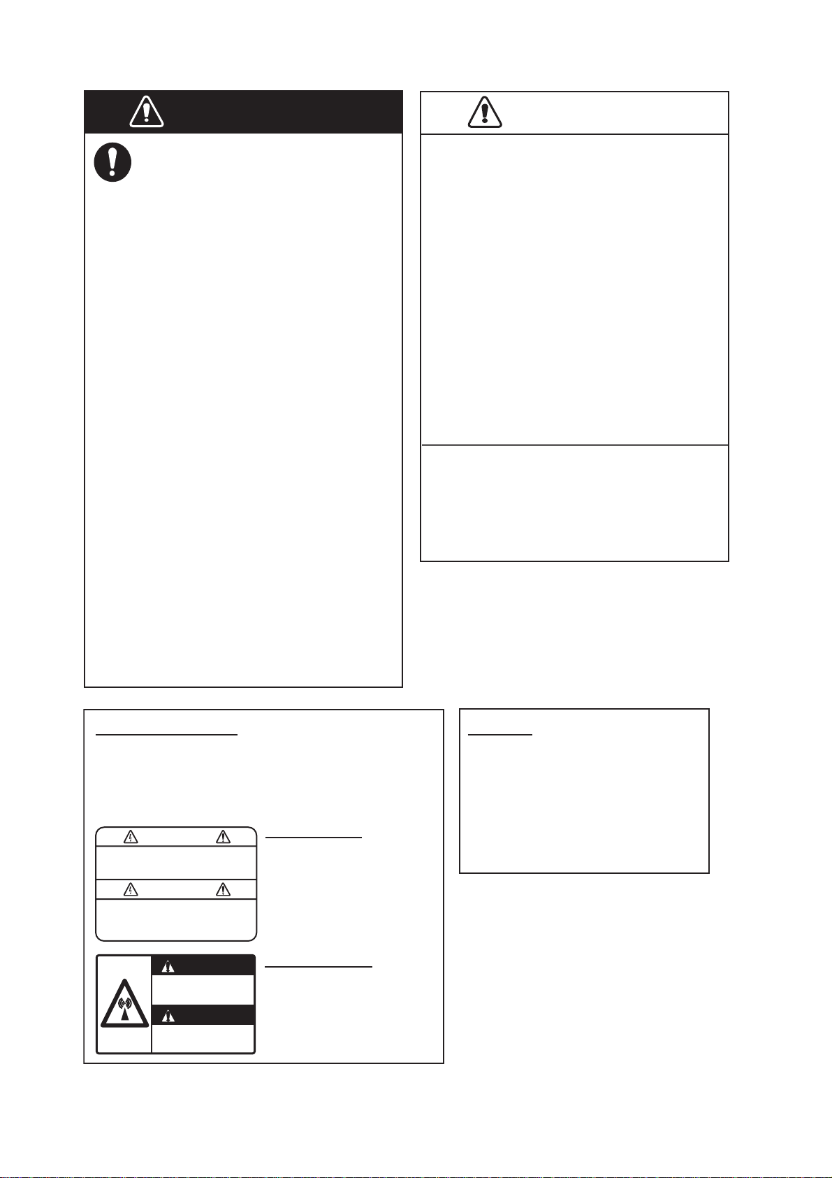
SAFETY INSTRUCTIONS
CAUTION
WARNING
Do not depend on one navigation
device for the navigation of the
ship. The navigator must check all
aids available to confirm position.
Electronic aids are not a
replacement for basic navigation
principles and common sense.
· The ARPA automatically tracks an
automatically or manually acquired
radar target and calculates its
course and speed, indicating them
by a vector. Since the data from the
auto plotter depend on the selected
radar targets, the radar must be
optimally tuned for use with the auto
plotter, to ensure required targets
will not be lost or unnecessary
targets like sea returns and noise
will not be acquired and tracked.
· A target is not always a landmass,
reef, ship, but can also be returns
from the sea surface and from
clutter. As the level of clutter
changes with the environment, the
operator must correctly adjust the
A/C SEA, A/C RAIN and GAIN
controls so that the target echoes do
not disappear from the radar screen.
CAUTION
The plotting accuracy and response of
this ARPA meets IMO standards.
The tracking accuracy is affected by the
following:
· The tracking accuracy is affected by
course change. One to two minutes is
required to restore vectors to full
accuracy after a sudden course change.
(The actual amount depends on
gyrocompass specifications.)
· The amount of tracking delay is inversely
proportional to the relative speed of the
target. Delay is on the order of 15-30
seconds for high relative speed; 30-60
seconds for low relative speed.
The data from ARPA and AIS are
intended for reference purposes only.
Check all available navigation aids to
determine target movement.
WARNING LABELS
Warning labels are attached to the equipment.
Do not remove any label. If a label is missing or
damaged, contact a FURUNO agent or dealer
about replacement.
WARNING
To avoid electrical shock, do not
remove cover. No user-serviceable
parts inside.
WARNING
Radiation hazard. Only qualified
personnel should work inside scanner.
Confirm that TX has stopped before
opening scanner.
DISPLAY UNIT
Name: Warning Label 1
Type:
Code No.: 100-236-233-10
ANTENNA UNIT
Name: Warning Sticker
Type:
Code No.: 100-266-890-10
86-003-1011-3
03-142-3201-0
TFT LCD
The high quality TFT (Thin Film
Transistor) LCD displays 99.999%
of its picture elements.
The remaining 0.001% may drop
out or light, however this is an
inherent property of the LCD; it is
not a sign of malfunction.
iv

TABLE OF CONTENTS
FOREWORD...................................................................................................................ix
SYSTEM CONFIGURATION.........................................................................................xii
1. DESCRIPTION OF OPERATION ..........................................................................1-1
1.1 Controls ......................................................................................................................1-1
1.2 How to Turn the Radar On/Off and Transmit.................................. ............................1-2
1.3 Display Indications......................................................................................................1-3
1.4 How to Adjust Display Brilliance, Panel Dimmer....................... .. ......................... ......1-4
1.5 Menu Description............................... ......................... ............................ ....................1-4
1.6 Tuning.........................................................................................................................1-6
1.7 Display Modes............................................................................................................1-7
1.7.1 How to select the display mode......................................................................1-7
1.7.2 Description of display modes ............................................. .. ..........................1-8
1.8 How to Select a Range Scale.....................................................................................1-9
1.9 How to Adjust the Gain (sensitivity)..........................................................................1-10
1.10 How to Reduce the Sea Clutter................................. .................... .................... .......1-11
1.11 How to Reduce the Rain Clutter...................... .. ................................................... .. ..1-12
1.12 Automatic Adjustments of S ea a n d Ra in Cl utters ............. .. .................... ... .. ............1 -1 3
1.13 Cursor.......................................................................................................................1-14
1.14 Interference Rejector........... .....................................................................................1-15
1.15 How to M easure the Range to a Target .................................................................. .1-16
1.15.1 How to adjust ra ng e rin g b rilliance .................... .. .. .......................................1-16
1.15.2 How to measure the range with a VRM ........................................................1-17
1.15.3 How to select VRM unit................................................................................1-17
1.16 How to M eas u re the Bearing to a Targe t..................................................................1-1 8
1.16.1 How to measure the b ear in g w ith a n EBL ...................... ..............................1-1 8
1.16.2 EBL reference ............................................................ .. .. ..............................1-1 9
1.17 How to Measure the Range and Bearing Between Two Targets.............................1-19
1.18 How to Select a Pulselength............................................................... .. ....................1-20
1.19 Target Alarm.............................................................................................................1-21
1.19.1 How to set a target alarm zone ....................................................................1-22
1.19.2 How to stop the audio alarm... ... ...................................................................1-22
1.19.3 How to select the alarm type........................................................................1-23
1.19.4 How to sleep a target alarm temporarily.......................................................1-23
1.19.5 How to deactivate a target alarm........................................................... .......1-24
1.19.6 How to sele ct the target strength which triggers a target alarm...................1-24
1.19.7 How to turn the buz z e r on / o ff .......................................................................1-24
1.20 How to Off-center the Display...................................................................................1-25
1.20.1 How to select the o ff -c e n te r m o d e................................................................1-25
1.20.2 Off-center the dis p la y ........... ........................................................................1 -2 5
1.21 Zoom ........................................................................................................................1-27
1.21.1 Zoom mode ..................................................................................................1-27
1.21.2 How to zoom .... .. ..........................................................................................1-2 7
1.22 Echo Stretch.............................................................................................................1-29
1.23 Echo Average...........................................................................................................1-29
1.24 Target Trails .............................................................................................................1-30
1.24.1 Trail time.......................................................................................................1-30
1.24.2 How to start, sto p the trails...........................................................................1-31
1.24.3 Trail mode ....................................................................................................1-31
1.24.4 Trail gradation ............................ .................... ..............................................1-32
1.24.5 Trail color......................................................................................................1-32
1.24.6 Trail level ......................................................................................................1-33
v

TABLE OF CONTENTS
1.24.7 How to restart, stop the trails .......................................................................1-33
1.24.8 Narrow trails.................................................................................................1-34
1.24.9 Your ship trail ...................... .. .......................................................................1 -3 4
1.25 How to Send the Target Position and Enter the Origin Mark................................. ..1-34
1.26 How to Hide the Heading Line Temporarily .............................................................1-35
1.27 Presentation Brilliance .............................................................................................1-35
1.28 Custo m S etu p ..........................................................................................................1-36
1.28.1 About custom setup.....................................................................................1-36
1.28.2 Description of custom setup items...............................................................1-36
1.28.3 How to set custom setups............................................................................1-37
1.29 How to Program Function Keys (F1, F2 and F3 keys).............................................1-38
1.30 Noise Rejector..........................................................................................................1-39
1.31 Wiper........................................................................................................................1-39
1.32 How to Reduce Second-trace Echoes....................... ......................... .. ...................1-40
1.33 Watchman................................................................................................................1-40
1.34 Color Selections.......................................................................................................1-41
1.34.1 Preset colors ................................................................................................1-41
1.34.2 Custom colors ..................... .. .......................................................................1-42
1.35 Navig a tion Data........ ... .. ...........................................................................................1 -4 3
1.35.1 Navigation data during standby....................................................................1-43
1.35.2 Navigation data at the bottom of the screen................................................1-43
1.36 Dynamic Range.......................................................................... .. ............................1-44
1.37 Chara c te r i s ti cs C u rv e.... .. .........................................................................................1-4 5
1.38 Waypo i nt M a r ke r......................................................................................................1-46
1.39 Alarm Message........................................................................................................1-46
1.40 Echo A re a ..... ... ........................................................................................................1-48
1.41 Initia l S ub M enu .......................................................................................................1-49
1.41.1 How to open the Initial sub menu........................................... ......................1-49
1.41.2 Description of Initial sub menu.....................................................................1-49
1.42 Unit s Su b Men u............... .. .......................................................................................1-51
1.43 Secto r B la n k....... .. .................................................................................................... 1-51
1.44 Other Menu Items ....................................................................................................1-53
1.44.1 Menu items on the [Brill/Color] menu...........................................................1-53
1.44.2 Menu it ems o n the [Display] menu............................ .................... ...............1-55
1.44.3 Menu items on the [Echo] menu..................................................................1-56
1.45 Remo te Di s p lay........................................................................................................1-56
2. DESCRIPTION OF RADAR...................................................................................2-1
2.1 General......................................................................................................................2-1
2.1.1 Minimum and maximum ranges.....................................................................2-1
2.1.2 Radar resolution.............................................................................................2-2
2.1.3 Bearing accuracy .................... .. .....................................................................2-3
2.1.4 Range measurement....... .. ......................... ............................ ........................2-3
2.2 False Echoes................................ ......................... ............................ ........................2-3
2.2.1 Multiple echoes..............................................................................................2-3
2.2.2 Sidelobe echoes.............................................................................................2-4
2.2.3 Virtual imag e ....................... .. .........................................................................2-4
2.2.4 Shadow sector........................... ......................... .. .........................................2-5
2.3 SART (Search and Rescue Transponder)................................... .. ............................2-6
2.3.1 SART desc ri p tio n .................... .......................................................................2-6
2.3.2 General remarks on receiving SART ................................. ............................2-7
2.4 RACON ......................................................................................................................2-8
vi

TABLE OF CONTENTS
3. ARPA OPERATION...............................................................................................3-1
3.1 Precaution s for Use....................................................................................................3-1
3.2 Controls for Use w it h ARP A ....... ................................................................................3-1
3.3 ARPA Display On/ O f f ........ .. .......................................................................................3-2
3.4 How to Acquire and Track the Targets....................... ................................................3-2
3.4.1 Manual acquisition..........................................................................................3-2
3.4.2 Automatic ac q u is it io n .................... .................... .. .. .........................................3-3
3.5 How to Stop the Tracking of ARPA Target.................................................................3-3
3.5.1 How to stop th e tr acking of selected tar g ets .................. .. ... ...........................3-3
3.5.2 How to stop th e tr ac k in g of all targets ................... .. ... ....................................3-3
3.6 Vector Attributes.........................................................................................................3-4
3.6.1 What is a vector?............................................................................................3-4
3.6.2 Vector time and vector reference....................... ...................................... ......3-4
3.6.3 Vector of your ship .........................................................................................3-5
3.7 History Display (target past positio n )......... .. ...............................................................3-6
3.8 ARPA Target Da ta...... .. ..............................................................................................3-7
3.9 CPA/TCPA Alarm.......................................................................................................3-8
3.10 Proximity Alarm ................. .. .. .....................................................................................3-9
3.11 Lost Target ...............................................................................................................3-10
3.12 Symbo l Co lo r............................................... .. ... ........................................................3-10
4. AIS OPERATION...................................................................................................4-1
4.1 Controls for Use w it h AI S ........ ...................................................................................4-1
4.2 AIS Display On/Off .....................................................................................................4-1
4.3 AIS Symbols...............................................................................................................4-2
4.4 Activating, Sleeping Targets.......................................................................................4-2
4.5 AIS Target Data..........................................................................................................4-3
4.6 How to Sort Targets....................................................................................................4-4
4.7 Display Range............................................................................................................4-4
4.8 How to Display the Targets within a Specific Sector..................................................4-5
4.9 Number of Targe ts to Display.....................................................................................4-5
4.10 Vector Attributes.........................................................................................................4-6
4.10.1 What is a vector?............................................................................................4-6
4.10.2 Vector time and vector reference.................. .................... .................... .........4-6
4.11 Hist or y Di sp lay (target past posit io n )......... .................................................................4-7
4.12 CPA/TCPA Alarm.......................................................................................................4-8
4.13 Proximity Alarm ................. .. .. .....................................................................................4-9
4.14 Lost Target .................................................................................................................4-9
4.15 Symbo l Co lo r............................................... .. ... ........................................................4-10
4.16 How to Ignore Slow Targets.....................................................................................4-10
5. GPS OPERATION .................................................................................................5-1
5.1 Navigator Mode..........................................................................................................5-1
5.2 Datum......................................................................................................................... 5-1
5.3 WAAS Setup...............................................................................................................5-2
5.4 Satellite Monitor..........................................................................................................5-3
5.5 Cold Start..... ...............................................................................................................5-4
6. MAINTENANCE, TROUBLESHOOTING................................................ ..............6-1
6.1 Preventive M a in t e n anc e.............................................................................................6-2
6.2 Fuse Replac e me n t .....................................................................................................6-3
6.3 Magnetron Life...................... ...................................... .................... ..................... .......6-3
6.4 LCD Backlight Life......................................................................................................6-3
6.5 Simple Troubleshooting.... ........................................................... ...............................6-4
6.6 Advanced-level Troubleshooting............................................................... .................6-5
6.7 Diagnostic Test...........................................................................................................6-7
vii

TABLE OF CONTENTS
6.8 LCD Test....................................................................................................................6-9
6.9 ARPA Test ......... .. .. ........................................ .. .. ......................................................6-10
6.10 GPS T es t................ .. ................................................................................................6-11
APPENDIX 1 MENU TREE .......................................................................................AP-1
APPENDIX 2 GEODETIC CHART LIST ...................................................................AP-5
SPECIFICATIONS .....................................................................................................SP-1
INDEX..........................................................................................................................IN-1
Declaration of Conformity
viii

FOREWORD
A Word to the Owner of the MODEL 1937 Marine Radar
Congratulations on your choice of the FURUNO MODEL 1937 Marine Radar. We are confident
you will see why the FURUNO name has become synonymous with quality and reliability.
For over 60 years FURUNO Electric Company has enjoy ed an enviabl e reputa tion fo r i nnovati ve
and dependable marine electronics equipment. This dedication to excellence is furthered by our
extensive global network of agents and dealers.
Your equipment is designed and constructed to meet the rigorous demands of the marine environment. However, no machine can perform its intended function unless properly installed and
maintained. Please carefull y read and follow the oper ation and main tenance procedures set forth
in this manual.
We would appreciate feedback from you, the end-user, about whether we are achieving our purposes.
Thank you for considering and purchasing FURUNO equipment.
Features
The MODEL 1937 displays ship, lands, etc. on a 10.4-inch colo r LCD. You can operate this equipment with the keys, knob controls and Cursorpad.
The main features are as shown below.
• The basic specifications of the MODEL 1937 are shown below:
Model
MODEL 1937 4 kW 48 nm 120 cm, Open 48 RPM
• Bright 10.4-inch LCD is visible in direct sunlight.
• An easy to understand user interface with on-screen menu
• “Fog-Free” color LCD provides clear view in any weather conditions.
• Echo area display with full screen provides observation of a wider range around the vessel.
• Optional Auto Plotter ARP-11 is available for ARPA operation.
• User programmable function keys
• AIS data can be displayed with connection of FURUNO AIS Transponder/Receiver.
Output
power
Max range
Size and type for
radar antenna
Antenna rotation
• Echoes in yellow, green, orange or multiple colors
ix

FOREWORD
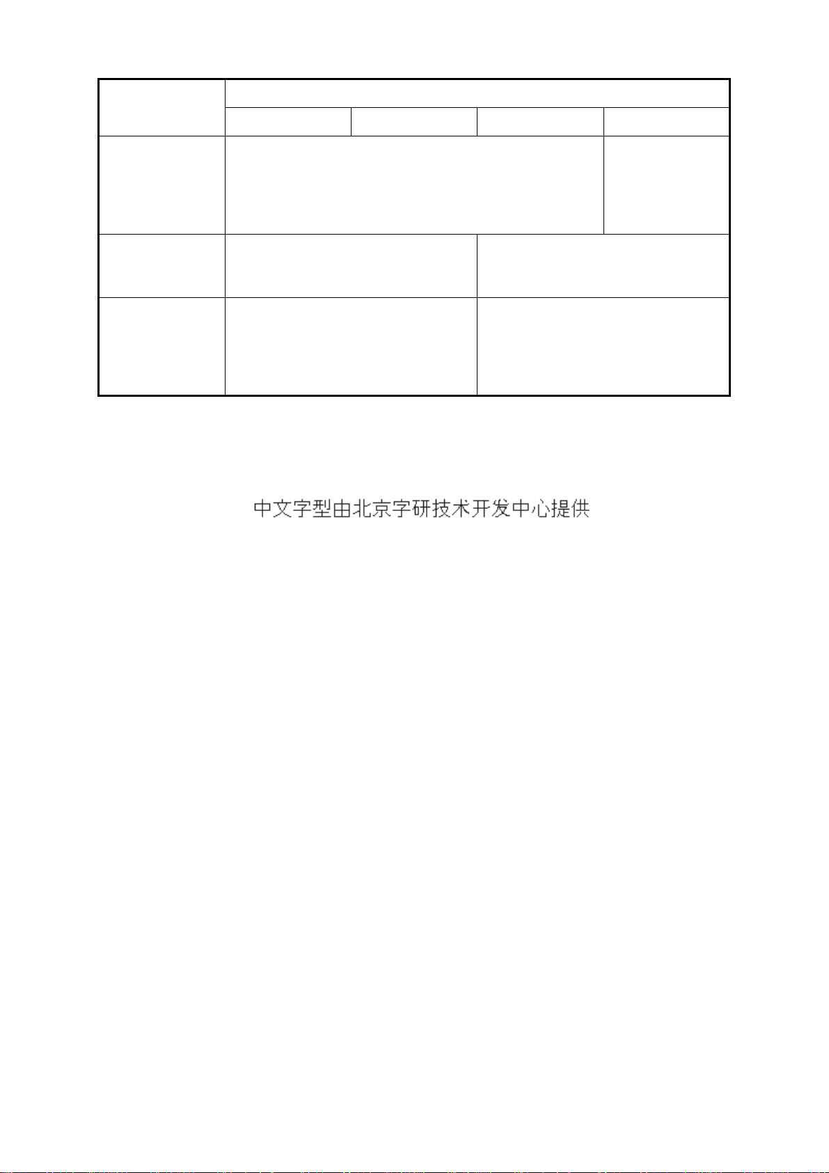
Radar Type and Function Availability
This radar is available in four types: [River], [Sea], [IEC] and [Russian-River], and function availability depends on type. The table below shows type and function availability.
[River]: For river, [Sea]: For sea, [IEC]: IEC compliant radar, [Russian-River]: For Russian river
Type and function availability
Type
Item
River Sea IEC Russian-River
Automatic menu
closure
Effective radius
dot count
Echo color Select the echo display color among
Echo color
customizing
Echo area Select the display area from [Normal]
Base text display Can show or hide the base text
Range preset Select the radar ranges to use. Can not select
Unit defaults
1) range
2) speed
Menu does not close automatically. Menu closes automatically when
there is no menu operation for 10
seconds.
240 dots 210 dots
Select the echo display color among
[Yellow], [Green], [Orange] or [Multi].
Can customize the echo display
color.
or [Full Screen].
indications.
1) KM
2) km/h,
m/s
1) NM
2) kn
[Yellow], [Green] or [Orange].
Can not customize the echo display
color.
Can not select. Display area is circle
only.
Can not hide the base text indica-
tions.
the radar ranges
to use.
1) KM
2) km/h,
m/s
Bearing scale Graduation every 1°, 5°, 10°, 30°, no
numeric indication, displayed in the
effective radius
VRM unit Can set the VRM unit independently
from the range unit.
Range unit Can change the range unit when
transmitting.
AIS symbol color Select the AIS symbol color from
[Green], [Red], [Blue], [White] or
[Black].
Vector reference Select the display mode for the vector
from [Relative] or [True].
Graduation every 1°, 5°, 10°, 30°,
numeric indication every 30°,
displayed out of the effective radius
Can not set the VRM unit independently from the range unit.
Can not change the range unit in
transmit. Only in standby.
Select the AIS symbol color from
[Green], [Blue], [White] or [Black].
[True]
x
Item
FOREWORD
Type
River Sea IEC Russian-River
Pulselength • 2NM/4KM/2SM: MP
• 4NM/8KM/4SM: LP
The rule for the
numbering of
ARPA targets
Marks temporary
hidden by pressing and holding
the CANCEL/HL
OFF key
Non-IEC system IEC system
Heading line, all marks (EBL, VRM,
target alarm zone, etc.)
Heading line, vector of your ship (with
ARP-11), north marker
• 2NM/4KM/
2SM: SP or
MP
• 4NM/8KM/
4SM: MP or LP
Note on Chinese font: The Chinese font used in this equipment is Ricoh Company Ltd.'s Ricoh
bitmap font.
xi
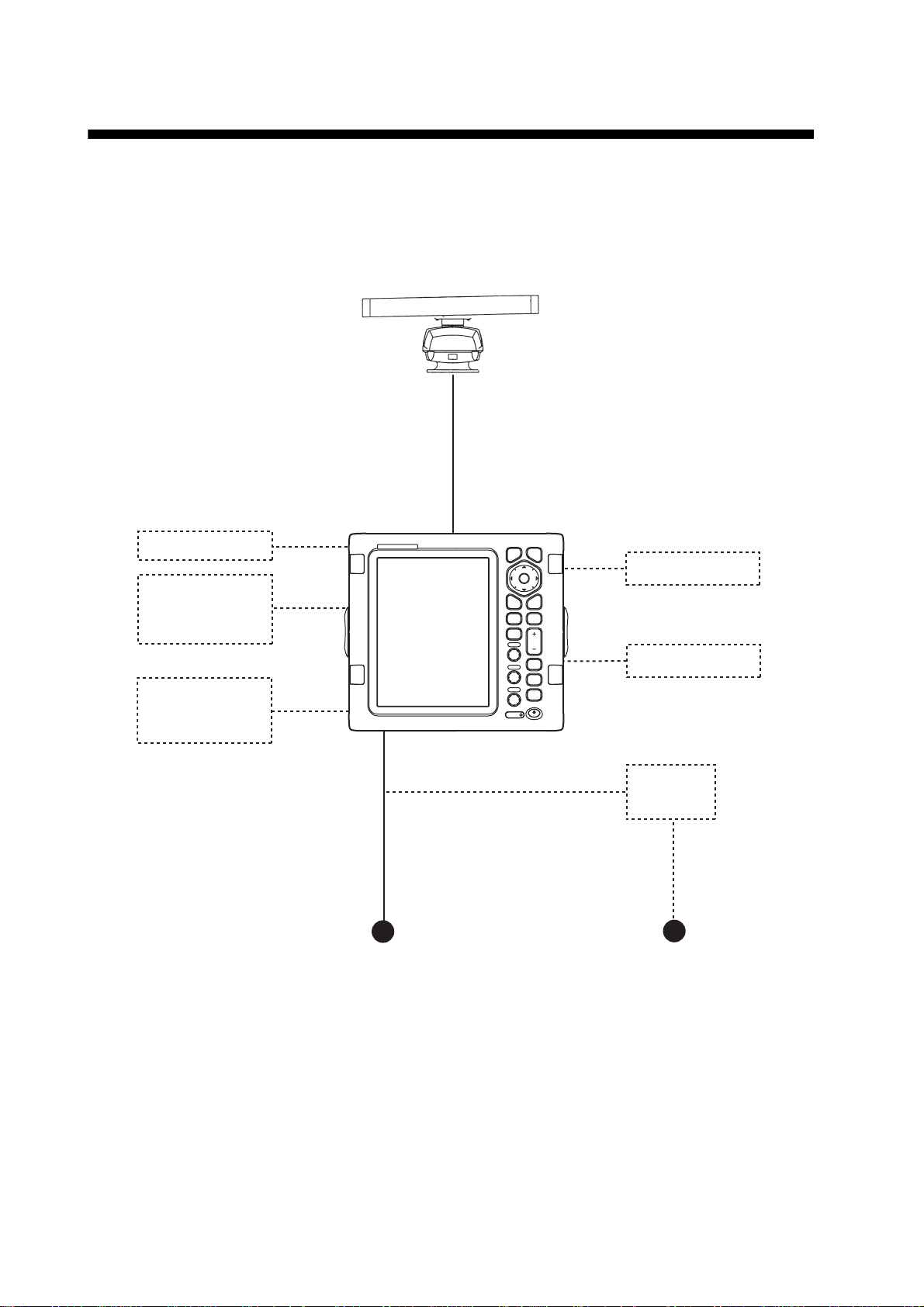
SYSTEM CONFIGURATION
Basic configuration is shown below with solid line.
MODEL 1937
Antenna unit
XN12A
RSB-0073-088A
Display unit
RDP-152
Heading sensor
Echo sounder,
GPS navigator,
AIS, etc.
Echo sounder,
GPS navigator,
AIS, etc.
12 - 24 VDC
MENU
EBL VRM
OFF
CENTER
TLL
GAIN
A/C SEA
A/C RAIN
ECONOMY
CANCEL
HL OFF
ENTER
TARGET
ALARM
RANGE
CUSTOM
TRAILS
STBY
T X
B
L
R
L
I
Remote display
External buzzer
Rectifier
RU-3423
100/110/115/220/230 VAC
xii
1. DESCRIPTION OF OPERATION
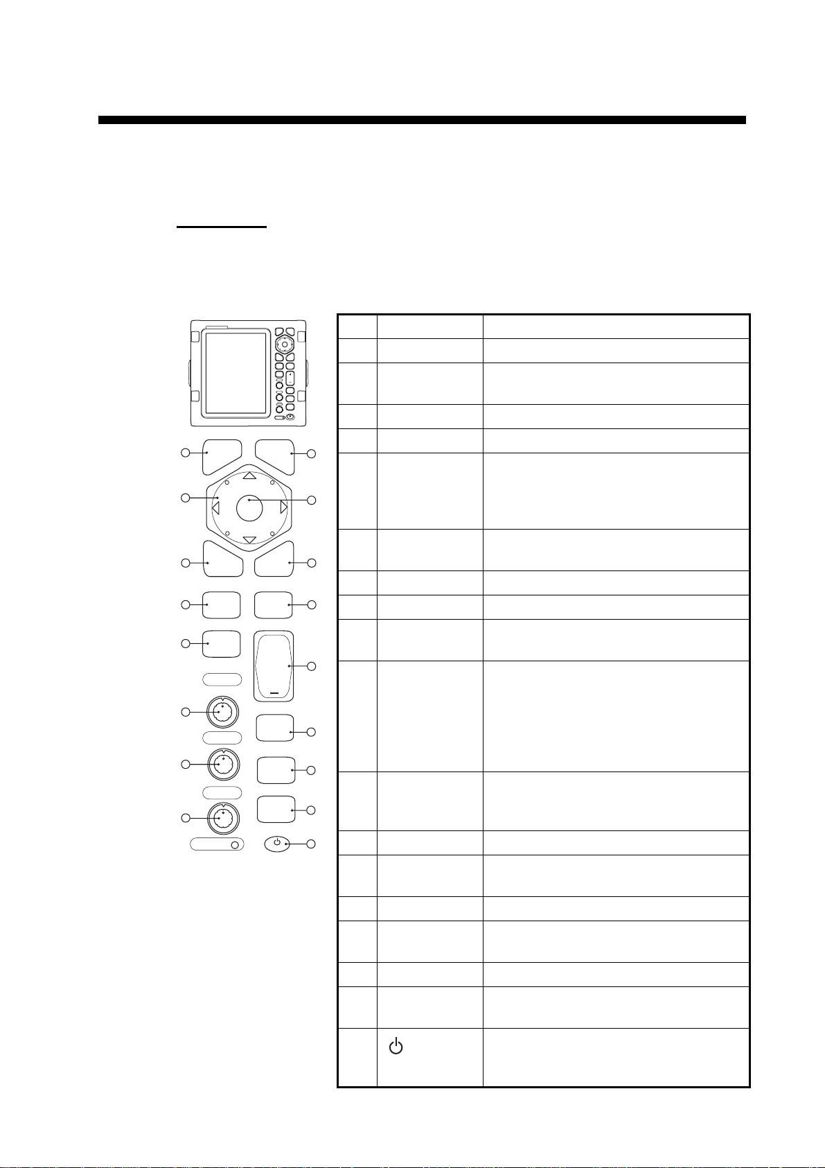
1.1 Controls
Display unit
The display unit has 16 keys which have labels with their functions, three knob controls and a Cursorpad. When you correctly operate this equipment, the unit beeps one
time. If your operation is wrong, the unit beeps three times.
1
2
3
4
5
6
7
8
MENU
OFF
CENTER
GAIN
F1
A/C SEA
F2
A/C RAIN
F3
EBL
TLL
ENTER
MENU
EBL VRM
OFF
CENTER
TLL
GAIN
A/C SEA
A/C RAIN
ECONOMY
CANCEL
HL OFF
VRM
TARGET
ALARM
+
RANGE
CUSTOM
TRAILS
STBY
TX
CANCEL
HL OFF
ENTER
TARGET
ALARM
RANGE
CUSTOM
TRAILS
STBY
T X
B
L
R
L
I
No. Control Description
1 MENU Open/close the menu.
2 Cursorpad Select the menu items and options.
Move the cursor.
3 EBL Measure the bearing to a target.
4 OFF CENTER Off-center the display.
9
5 TLL Send the latitude and longitude position
of a target to a navigation plotter.
10
Enter an origin mark at the cursor posi-
tion on the radar display.
6 GAIN Rotating: Adjust the sensitivity of the ra-
11
dar receiver.
7 A/C SEA Rotating: Reduce the sea clutter.
12
8 A/C RAIN Rotating: Reduce the rain clutter.
6,
F1, F2, F3 Push: Activate the function given to the
7, 8
13
9 CANCEL/ HL
OFF
key.
Erase the heading line while you press
this key. Cancel last entry in menu oper-
ation. Cancel the tracking of ARPA tar-
14
15
get. Remove data of selected ARPA or
AIS target from the data box. Return
one layer in multiple level menu.
10 ENTER Save selected menu option. Acquire
16
ARPA target. Select ARPA or AIS target
to display its data.
ECONOMY
11 VRM Measure the range to a target.
17
B
L
R
I
L
12 TARGET
ALARM
Set the target alarm, which checks for
targets in the operator-set area.
13 RANGE Select the detection range.
14 CUSTOM Preset the radar controls for one-touch
operation of radar.
15 TRAILS Plot the radar echo movement.
16 STBY/TX Transmit the radar pulses and put the
radar in standby alternately.
17
/BRILL
Short press: Turn on the power. Adjust
the brilliance.
Long press: Turn off the power.
1-1
 Loading...