

Furuno USA 9ZWRTR085, 9ZWRTR086 Users Manual

MARINE RADAR
FR-8062, FR-8122, FR-8252
SAFETY INSTRUCTIONS
WARNING
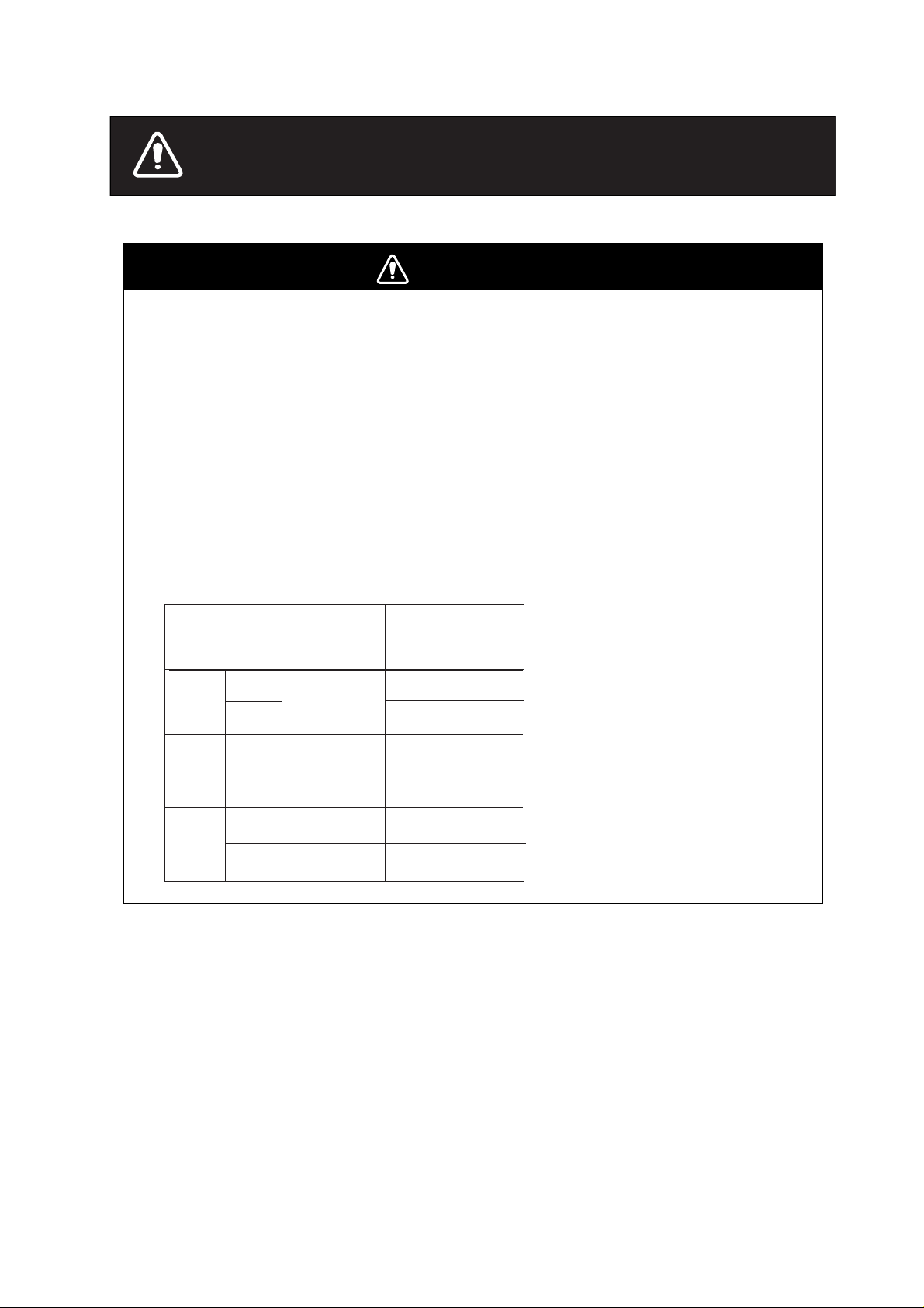
Radio Frequency Radiation Hazard
The radar antenna emits electromagnetic radio frequency (RF) energy which can be
harmful, particularly to your eyes. Never look directly into the antenna aperture from a
close distance while the radar is in operation or expose yourself to the transmitting
antenna at a close distance.
Distances at which RF radiation levels of 100 and 10 W/m
2
exist are given in the table
below.
Note: If the antenna unit is installed at a close distance in front of the wheel house,
your administration may require halt of transmission within a certain sector of antenna
revolution. This is possible. Ask your FURUNO representative or dealer to provide
this feature.
MODEL
FR-8062
FR-8122
FR-8252
XN-12A
XN-13A
XN-12A
XN-13A
XN-12A
XN-13A
Distance to
100 W/m
point
Nil
Worst case
0.50 m
Worst case
0.30 m
Worst case
0.80 m
Worst case
0.70 m
Distance to
2
10 W/m
Worst case
Worst case
Worst case
2
point
2.50 m
2.30 m
7.50 m
Worst case
7.00 m
Worst case
9.50 m
Worst case
9.00 m
i
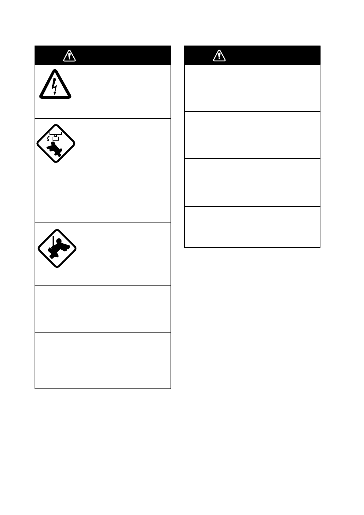
WARNING
WARNING
ELECTRICAL SHOCK HAZARD
Do not open the equipment.
Only qualified personnel
should work inside the
equipment.
Turn off the radar power
switch before servicing the
antenna unit. Post a warning sign near the switch
indicating it should not be
turned on while the antenna
unit is being serviced.
Prevent the potential risk of
being struck by the rotating
antenna and exposure to
RF radiation hazard.
Wear a safety belt and hard
hat when working on the
antenna unit.
Use the proper fuse.
Fuse rating is shown on the equipment.
Use of a wrong fuse can result in damage
to the equipment.
Keep heater away from equipment.
Heat can alter equipment shape and melt
the power cord, which can cause fire or
electrical shock.
Do not place liquid-filled containers on
the top of the equipment.
Fire or electrical shock can result if a liquid
spills into the equipment.
Do not operate the equipment with wet
hands.
Electrical shock can result.
Serious injury or death can
result if someone falls from
the radar antenna mast.
Do not disassemble or modify the
equipment.
Fire, electrical shock or serious injury can
result.
Turn off the power immediately if water
leaks into the equipment or the equipment is emitting smoke or fire.
Continued use of the equipment can cause
fire or electrical shock.
ii

WARNING
WARNING
o
CAUTION
No one navigational aid should be relied
upon for the safety of vessel and crew.
The navigator has the responsibility to
check all aids available to confirm
position. Electronic aids are not
a substitute for basic navigational
principles and common sense.
• This ARP automatically tracks
automatically or manually acquired radar
targets and calculates their courses and
speeds, indicating them by vectors. Since
the data generated by the auto plotter
are based on what radar targets are
selected, the radar must always be
optimally tuned for use with the auto
plotter, to ensure required targets will not
be lost or unwanted targets such as sea
returns and noise will not be acquired
and tracked.
• A target does not always mean a land mass, reef, ships or other surface vessels
but can imply returns from sea surface
and clutter. As the level of clutter changes
with environment, the operator should
properly adjust the A/C SEA, A/C RAIN
and GAIN controls to be sure target
echoes are not eliminated from the
radar screen.
The plotting accuracy and response of
this ARP meets IMO standards.
Tracking accuracy is affected by the
following:
• Tracking accuracy is affected by course
change. One to two minutes is required t
restore vectors to full accuracy after an
abrupt course change. (The actual
amount depends on gyrocompass
specifications.)
• The amount of tracking delay is inversely
proportional to the relative speed of the
target. Delay is on the order of 15—30
seconds for high relative speed; 30—60
seconds for low relative speed.
The data generated by ARP, AIS and
video plotter are intended for
reference only.
Refer to official nautical charts for
detailed and up-to-date information.
iii
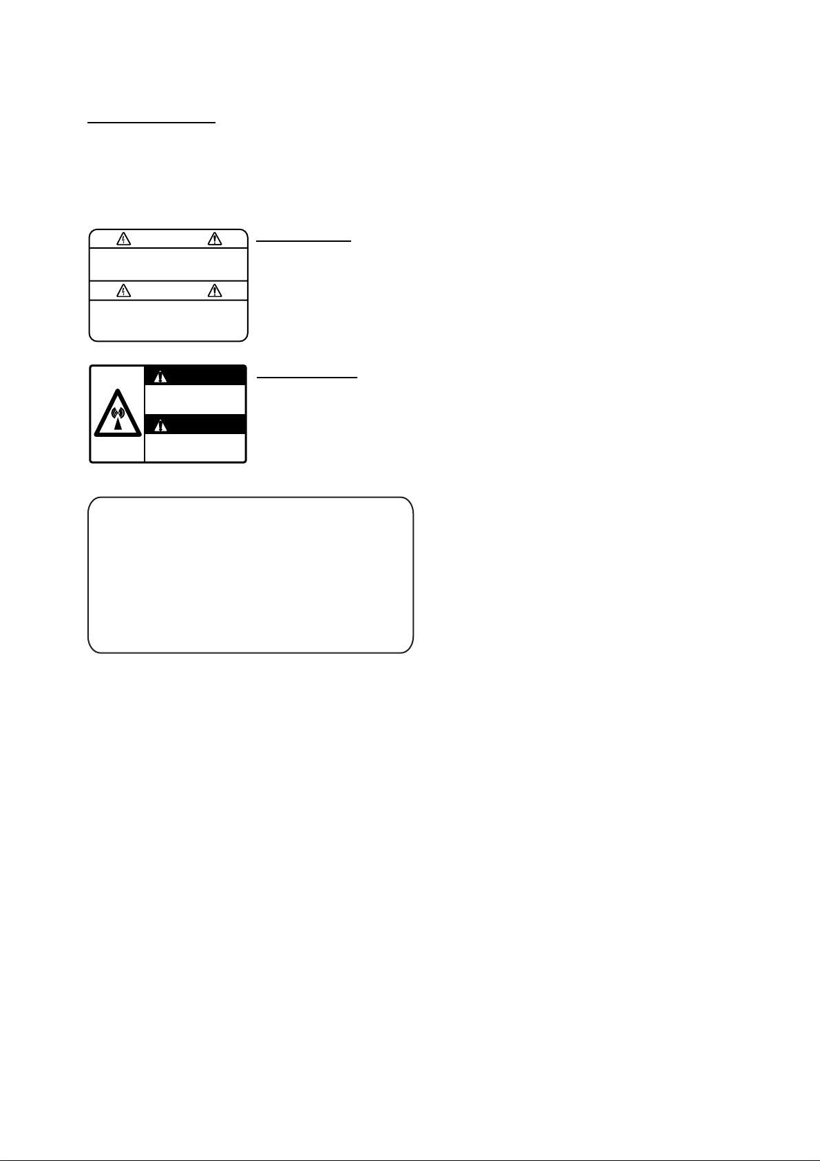
WARNING LABEL
ARNING
Warning labels are attached to the
equipment. Do not remove any label.
If a label is missing or damaged,
contact a FURUNO agent or dealer
about replacement.
WARNING
To avoid electrical shock, do not
remove cover. No user-serviceable
parts inside.
WARNING
Radiation hazard. Only qualified
personnel should work inside scanner.
Confirm that TX has stopped before
opening scanner.
DISPLAY UNIT
Name: Warning Label (1)
Type: 86-003-1011-0
Code No.: 100-236-230
ANTENNA UNIT
Name: Radiation Warning Label
Type: 03-142-3201-0
Code No.: 100-266-890
TFT LCD
The high quality TFT (Thin Film Transistor)
LCD displays 99.999% of its picture elements. The remaining 0.01% may drop out
or light, however this is an inherent property
of the LCD; it is not a sign of malfunction.
iv

TABLE OF CONTENTS
FOREWORD...............................................................................................ix
SYSTEM CONFIGURATION ......................................................................xi
1. OPERATIONAL OVERVIEW..............................................................1-1
1.1 Controls.....................................................................................................................1-1
1.2 Turning the Radar On/Off, Transmitting....................................................................1-4
1.3 Display Indication s........ ............... .............. ............... ............... .............. ............... .....1-5
1.4 Display Brilliance, Pane l Dimmer .................. ............... .............. ............... ................1- 6
1.5 Menu Overview..........................................................................................................1-6
1.6 Tuning........................................................................................................................1-7
1.7 Presentation Modes........................ .... ............... .............. ............... ............... ............1-8
1.8 Choosing a Range Scale.........................................................................................1-10
1.9 Choosing a Pulse Length ........................................................................................1 -11
1.10 Adjusting the Sensitivity...........................................................................................1-11
1.11 Suppressing Sea Clutter..........................................................................................1-12
1.12 Suppressing Rain Clutter.........................................................................................1-13
1.13 Automatic Suppression of Sea and Rain Clutters ...................................................1-14
1.14 Cursor ......................................................................................................................1-15
1.15 Interference Rejector...............................................................................................1-16
1.16 Measuring the Range to a Target............................................................................1-17
1.17 Measuring the Bearing to a Target..........................................................................1-19
1.18 Measuring the Range and Bearing Between Two Targets......................................1-20
1.19 Target Alarm ............................................................................................................1-21
1.20 Off Centering the Display ........................................................................................1-24
1.21 Zoom .......................................................................................................................1-25
1.22 Echo Stretch............................................................................................................1-26
1.23 Echo Averaging.......................................................................................................1-27
1.24 Target Trails ............................................................................................................1-28
1.25 Parallel Index Lines .................................................................................................1-31
1.26 Outputting Target Position, Inscribing Origin Mark..................................................1-32
1.27 Temporarily Hiding the Heading Line, Heading Marker...........................................1-33
1.28 Custom Setup ..........................................................................................................1-34
1.29 Programming Function Keys (F1 and F2 keys)............... .... ............... .............. .......1-36
1.30 Noise Rejector.......... ............... ............... .............. .............................. .............. .......1-36
1.31 Suppressing Second-trace Echoes.........................................................................1-37
1.32 Watchman ...............................................................................................................1 -37
1.33 Color Schemes........................................................................................................1-38
1.34 Navigation Data.......................................................................................................1-39
1.35 Dynamic Range....................... ............... .............. .............................. .............. .......1-41
1.36 Characteristics Curve ..............................................................................................1-42
1.37 Antenna Speed ........................................................................................................1-42
1.38 Waypoint Mark.........................................................................................................1-43
1.39 Alarm Message Display...........................................................................................1-44
1.40 Echo Area................................................................................................................1-45
1.41 Customizing (Initial Menu).......................................................................................1-46
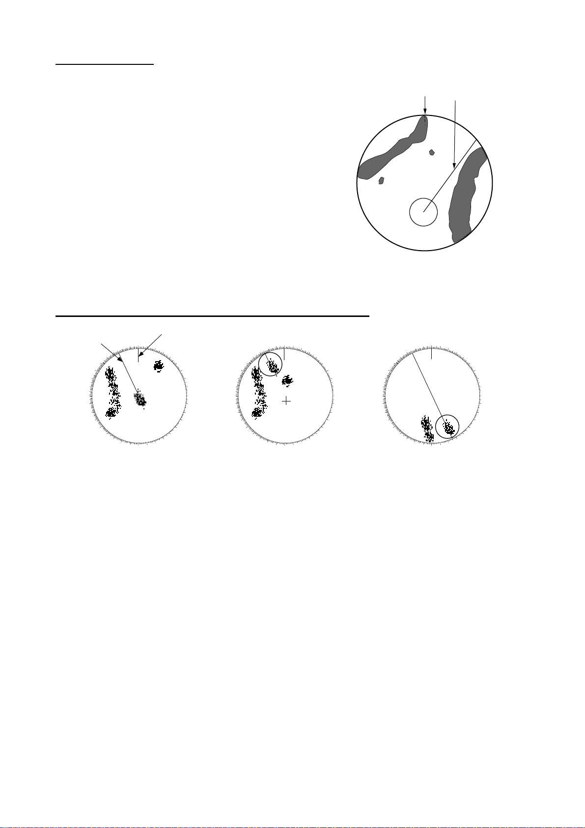
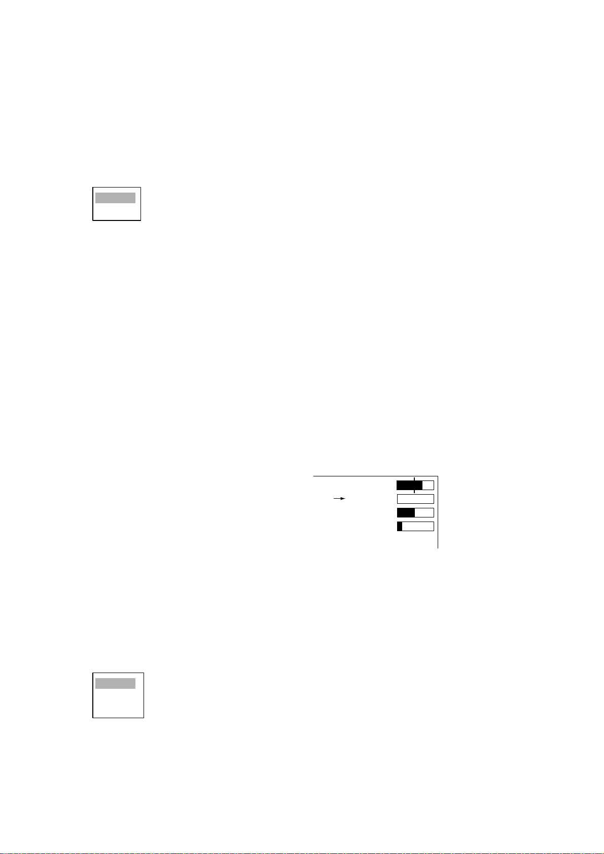
2. RADAR OBSERVATION ....................................................................2-1
2.1 General......................................................................................................................2-1
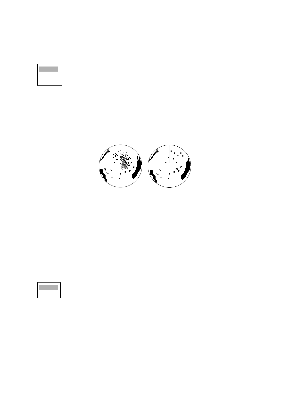
2.2 False Echoes....................... ............... ............... .............. ............... ............... ............2-3
2.3 SART (Search and Rescue Transponder)........................... ............... .............. .........2-5
2.4 RACON......................................................................................................................2-6
v

3. ARP OPERATION..............................................................................3-1
3.1 Usage Precautions....................................................................................................3-1
3.2 Controls for Use with ARP ........................................................................................ 3-2
3.3 ARP Display On/Off .......... ............... .............. ............... ............... .............................3-2
3.4 Acquiring and Tracking Targets................................................................................3-3
3.5 Terminating Tracking of ARP Targets .......................................................................3-4
3.6 Vector Attributes........................................................................................................3-5
3.7 History Display (target past position) ........................................................................3-6
3.8 ARP Target Data............... ............... .............. ............... ............... .............. ...............3-7
3.9 CPA and TCPA Alarm......................... ............... ............... ............................. ...........3-8
3.10 Proximity Alarm.........................................................................................................3-9
3.11 Lost Target................................................................................................................3-9
3.12 Symbol Color...........................................................................................................3-10
4. AIS OPERATION................................................................................ 4-1
4.1 Controls for Use with AIS.........................................................................................4-1
4.2 Activating, Deactivat i ng the AIS Function......................... .............. ............... ...........4-1
4.3 Turning the AIS Display On or Off.............................................................................4-2
4.4 AIS Symbols..............................................................................................................4-2
4.5 Activating Targets .....................................................................................................4-2
4.6 Displaying AIS Target Data.......................................................................................4-3
4.7 Display Range............ .............. ............... ............... .............. ............... ............... .......4-4
4.8 Sorting Targets.............. ............... ............... .............. ............... ............... .............. ....4-4
4.9 Display Sector........ ............... .............. .............................. .............. ............... ...........4-5
4.10 Number of Targets to Display ...................................................................................4-5
4.11 Vector Attributes........................................................................................................4-6
4.12 History Display (target past position) ........................................................................4-7
4.13 CPA and TCPA Alarm......................... ............... ............... ............................. ...........4-8
4.14 Proximity Alarm.........................................................................................................4-9
4.15 Lost Target................................................................................................................4-9
4.16 Symbol Color...........................................................................................................4-10
5. GPS OPERATION..............................................................................5-1
5.1 Navigator Type..........................................................................................................5-1
5.2 Datum........................................................................................................................5-2
5.3 WAAS Setup.............................................................................................................5-2
5.4 Sate llit e M onitor ........................................................................................................5-3
5.5 Type 16 Message......................................................................................................5-4
5.6 GPS Sensor Installation Position Offset....................................................................5-5
5.7 Cold Start...................... ............... ............... .............. ............... ............... .............. ....5-6
6. MAINTENANCE & TROUBLESHOOTING ........................................6-1
6.1 Preventive Maintenance............................................................................................6-2
6.2 Replacement of Fuses ..............................................................................................6-3
6.3 Replacing the Magnetron..........................................................................................6-3
6.4 Trackball Maintenance..............................................................................................6-4
6.5 SImple Troubleshooting ............................................................................................6-5
6.6 Advanced-level Trouble shoot ing................. .............. ............... ............... .............. ....6-6
6.7 System Test..............................................................................................................6-8
6.8 LCD Test.................................................................................................................6-10
6.9 GPS Test.................................................................................................................6 -11
6.10 Clearing the Memory...............................................................................................6-12
SPECIFICATIONS................................................................................. SP-1
INDEX......................................................................................................IN-1
vi

FOREWORD
A Word to the Owner of the FR-8xx2 Marine Radar
FURUNO Electric Company thanks you fo r purch as ing t he FR- 8xx2 Colo r LCD Marin e Rada r series. We are confident you will disc over why the FURUN O name has become synonymo us w it h
quality a nd reliability.
For over 50 years FURUNO Electric Co mpany has enjoye d an enviable r eputatio n for quality a nd
reliability throughout the world. This dedication to excellence is furthered by our extensive global
network of agents and dealers.
Your equ ipment is de si gned and constructed to meet the rigorous demand s of th e m arine environment. However, no machine can perform its intended function unless properly installed and
maintained. Please carefully read and follow the operation and maintenance procedures set forth
in this manual.
We woul d appreciate f eedback fr om y ou, the end-user, about w hether w e are achieving our purposes.
Thank you for considering and purchasing FURUNO.
Features
The FR-8xx2 series display radar targets on a bri ght 12.1" color LCD. Operati on is si mplified wit h
the combination of discrete keys and trackball.
The main fe at ures are as fo llows:
• The FR-8xx2 serie s co ns is ts of th e f ollowing models:
Model, output, max, range, antenna type
Model Output Range Radar Antenna
FR-8062 4.9 kW 72 nm/sm, 96 km 4 or 6 ft radiator
FR-8122 12 kW 72 nm/sm, 96 km 4 or 6 ft radiator
FR-8252 25 kW 96 nm/km/sm 4 or 6 ft radiator
• Bright 12. 1" LCD visible even un der direct su nlight
• Use r-friendly operation with combination of discrete keys, soft keys, and trackball
• Antenna speed may be autom at ic ally selected according to pulse length or speed
• Built in ARP optionally available
• A IS data shown with connection of AIS transponder
• Use r programmable function keys
• O ne touch setup of major controls with custom setup feature
• Echoes in y ellow or gree n or colors of red, y ellow or green in order of descending strengt h.
vii

Notice
• No part of this manual may be copied or reproduced without written permission.
• Th is manual is lost or worn, contact your dealer about replacement.
• The con te nts of t his m anual and equipmen t specifications are subject to change witho ut
notice.
• Th e example screens (or illustrations) shown in this manual may not match the screens you
see on your display. The screen you see depends on your system configuration and equipment settings.
• This manual is intended for use by native spe ak ers of Englis h.
• FURUNO will as s ume no responsibili ty f or t he damage ca us ed by improper use or modification of the equipme nt or c laims of loss of prof it by a t hird party.
viii
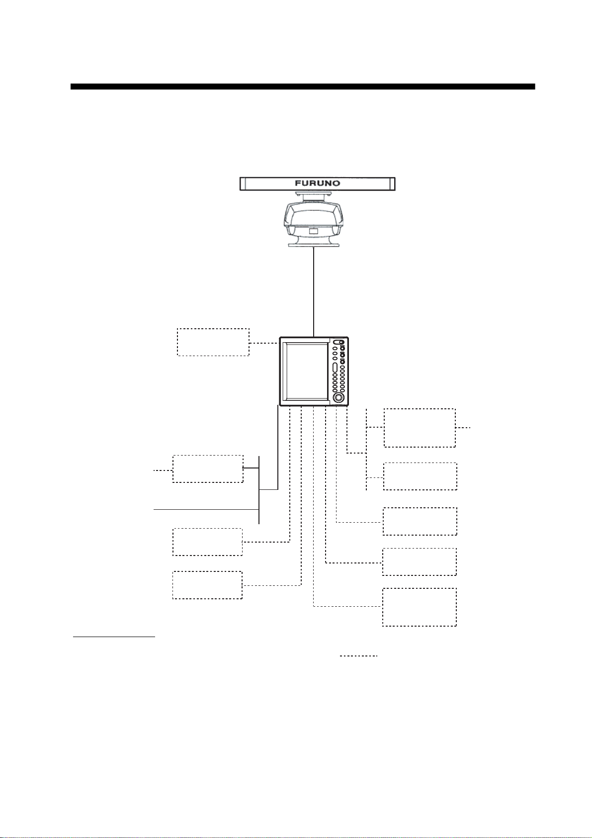
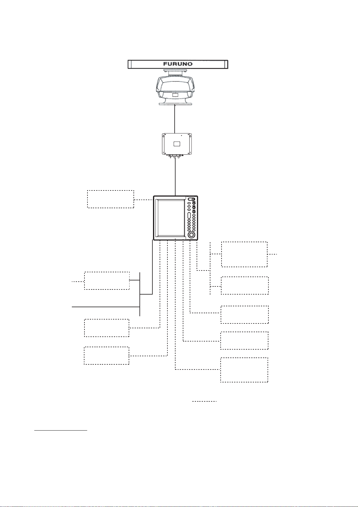
SYSTEM CONFIGURATION
ANTENNA UNIT
RSB-0070-085-XN12A/XN13A: FR-8062
RSB-0073-085-XN12A/XN13A: FR-8062
RSB-0073-086-XN12A/XN13A: FR-8122
Auto Plotter
ARP-11
(built in
display unit)
100/110/
115/220/
230 V AC , 1
12-24 VDC
φ
Rectifier
RU-3423
Remote
Display
SVGA
Monitor
Category of units
Antenna unit: Exposed to weather
All other units: Protected from weather
DISPLAY UNIT
RDP-150
Converter
AD-100
Heading Sensor
PG-1000
DEVICE
DEVICE
External
Buzzer
OP03-136
: Optional equipment
Gyro
Gyrocompass
NMEA
NMEA
FR-8062/8122
ix
ANTENNA UNIT
RSB-0073-087-XN12A/XN13A
POWER SUPPLY UNIT
PSU-008
100/110/
115/220/
230 V AC , 1
12-24 VDC
Auto Plotter
ARP-11
(built in
display unit)
Rectifier
φ
RU-3423
Remote
Display
SVGA
Monitor
DISPLAY UNIT
RDP-150
Converter
AD-100
Heading Sensor
PG-1000
DEVICE
DEVICE
External
Buzzer
OP03-136
Gyro
Gyrocompass
NMEA
NMEA
Category of units
Antenna unit: Exposed to weather
All other units: Protected from weather
x
: Optional equipment
FR-8252
1. OPERATIONAL OVERVIEW
This chapt er provide s th e inf ormation necessar y for operating this radar.
1.1 Controls
1.1.1 Display unit
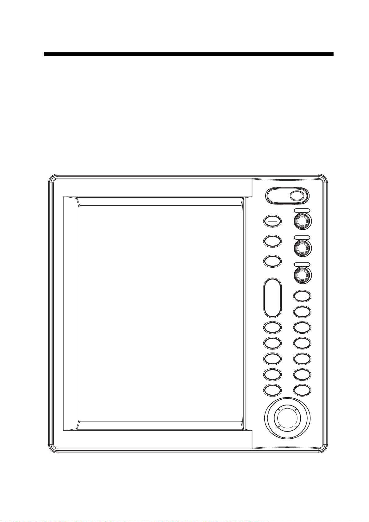
This radar is operated with the controls of the display unit (and the remote controller). 17 keys are
labeled and they provide the function shown on their labels. The trackball's main function is to
move the cursor across the screen. When you correctly execute an operation, the unit generates
a beep. Invalid operation causes the unit to emit several beeps.
POWER
BRILL
GAIN
STBY
TX
PUSH AUTO/MAN
MODE
SEA
CUSTOM
+
RANGE
-
ZOOM
TARGET
ALARM
EBL
ENTER
PUSH AUTO/MAN
RAIN
PUSH AUTO/MAN
F1
F2
OFF
CENTER
TRAILS
VRM
TLLMENU
CANCEL
HL OFF
Display unit
1-1

1. OPERATIONA L OVERVIEW
Control description
Control Descripti on
POWER/BRILL Momentary press: Turns power on; adjusts brilliance.
Long press: Turns power off.
STBY/TX Ttransmits radar pulses and places radar in standby alternately.
MODE Chooses presentation mode.
CUSTOM Presets radar controls for one-touch setup of r adar.
RANGE Chooses radar range.
ZOOM Zooms chosen target.
T ARGET ALARM Sets target alarm, which watches for targets entering or exiting the user-
set alarm zone.
EBL Measures bearing to a radar target.
MENU Open/closes the menu.
ENTER Registers chosen menu option; acquires ARP target; displays data of
selected ARP or AIS target.
GAIN Adjusts the sensitivity of the radar receiver.
SEA Suppresses sea clutter.
RAIN Suppresses rain clutter.
F1, F2 Programmable function keys.
OFF CENTER Shifts own ship position.
TRAILS Plots radar echo movement.
VRM Measure range to a radar target.
TLL Outputs position of chosen target to navigation plotter or inscribes mark
at cursor location, or both.
CANCEL/HL OFF Cancels last entry in menu operation; temporarily erases heading line;
cancels tracking of ARP target; removes data of selected ARP or AIS
target from data box; goes back one “layer” in multi-layer menu.
Trackball Chooses menu items; shifts display and cursor.
1-2
1. OPERATIONAL OVERVIEW
1.1.2 Remote controller
The remote controller provides armchai r contr o l over trans mit , standby, ran te and display offcentering.
Offcenters display.
OFF
CENTER
RANGE
STBY
TX
Toggles STBY/TX
Chooses range.
Remote controller
1-3
1. OPERATIONA L OVERVIEW
1.2 Turning the Radar On/Off, Transmitting
Press the POWER/BRILL key at the upper right-hand corner of the c ontrol pane l to tu rn on the
radar on. Press and hold down the key until the screen turns black to turn the radar off.
At power -up the start -up screen appears as s hown right. The mode l name and pr ogram number
are sh own an d th e ROM and RAM are t este d. I f "NG " ap pears as th e re sult s of t he RO M and RAM
tests, try pressi ng an y ke y to pro ceed. If n ormal o pe r at ion is no t possi b le, co nt act you r deale r for
advice. After the test s are completed, the bearing scale and a digital timer appear. The dig ital timer
count s do wn the ti me re main ing t o wa rm up the magn etro n, wh ich tran smit s t he rad ar pu lses . Th is
warm-up takes 90 sec. (FR-8252) or 180 sec. (FR-8062, FR-8122).
12.1" Color LCD
Marine Radar
FR-8xx2
Model name appears here.
FURUNO ELECTRIC CO., LTD.
ROM: OK RAM: OK
Program No. 0317010-XX.XX
Start-up screen
After the timer has counted down to 0:00, the indication STBY appears at the screen center,
meaning the radar is now ready to tr ansmit radar pulses. Press the STBY/TX key to transmit radar
pulses.
The STBY/TX key toggles between stand-by and tr ansmit sta tus. The antenna rotat es in tr ansmit
condition and is stopped in standby. Because the magnetron ages with use it is highly recommended to set the radar in standby when it will not be required for an extended period of time. This
will help exte nd the lif e of the magne t ron.
Quick start
Provided that the radar was once in use with the transmitter tube (magnetron) still warm, you can
get the radar into TRANSMIT condition without the warm-up. If the POWER/BRILL key was
turned off by mistake or the like and you wish to restart the radar promptly, turn on the POWER/
BRILL key not later than 10 seconds after p ower-o ff. This feature is not available with the FR-
8252.
1-4
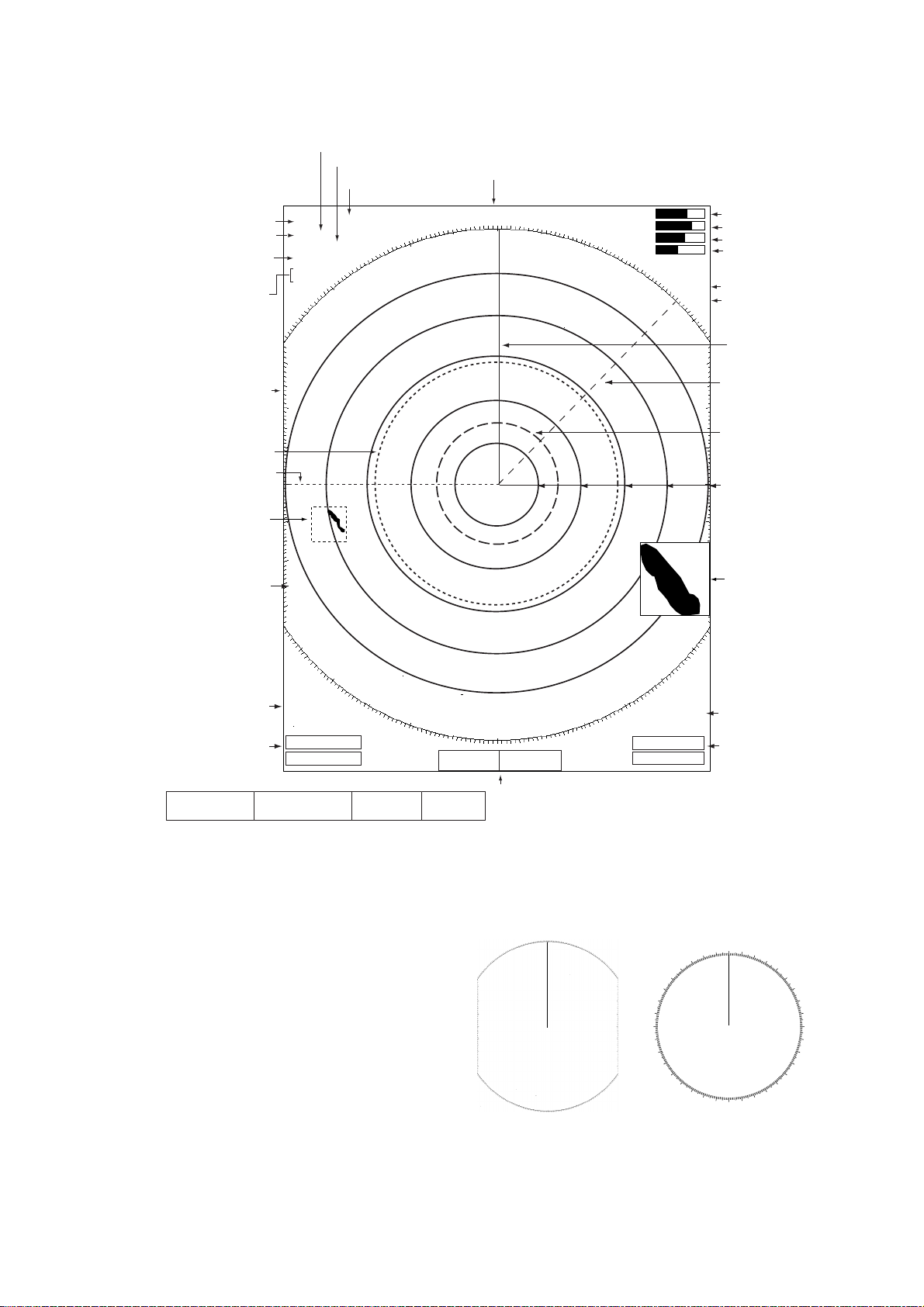
1.3 Display Indications
0
Presentation mode
Custom settings
Range ring interval
1. OPERATIONAL OVERVIEW
Heading
Range
Pulse length
Echo stretch (ES),
Echo averaging (EAV)
Noise rejector (NR),
Interference rejector (IR)
Bearing scale
VRM1
EBL1
Zoom cursor
Cursor
3
SP NUP
HARBOR A/C AUTO
ES1 EAV1
NR LOW
IR LOW
0.5
NM
+
+
359.9°
M
TUNE AUTO
GAIN AUTO
SEA MED
RAIN LOW
2ND ECHO
ZOOM
TUNE indicator
GAIN indicator
SEA indicator
RAIN indicator
2nd echo rejector
Zoom
Heading line
EBL2
VRM2
Range ring
+
Zoom
window
Trail ref.,
Trail time
EBL1, EBL2
bearing
OWN LAT: 34°56.123 E
SHIP LON: 135
SPEED 12.34 kt
Nav data:
°
34.567 E
Appears at screen bottom when Data Box in the
TRAILS (T)
01H30M00S
EBL1>270.0°R<
EBL2 045.0°
CURSOR LAT: 34°56.123 E
TTG: 01:00
LON: 135
°
34.567 E
R
WAY 0.095 NM
POINT 90.0
TTG: 00:20
+ 242.8°R 2.782 NM
TEMP 12.3
°
M
DEPTH 56.7 M
Display sub menu is set to "Nav" or "All". Appropriate sensors
required to display nav data.
Display indications
Note: The screen configuration, chosen during
the installation, is available in three types,
“Sea”, “River” and “IEC”, and the default configuration is “Sea”. The majority of the descriptions in this manual use the “Sea” configuration.
The majo r dif f erence betw een the Se a, R iv er
and IEC configurations is the be aring scale - it
is elliptic al on the Sea and River types and circular on the IEC type.
ALARM2_OUT
VRM1>1.430<NM<
VRM2 0.742
Cursor data
°
C
(Range and bearing or L/L position)
300
270
240
Bearing scale for Sea and
River configurations
ALARM1_IN
NM
330
210
Alarm status
VRM1, VRM2
range
000
180
Bearing scale for
IEC configuration
030
060
09
120
150
1-5
1. OPERATIONA L OVERVIEW
Menu
Echo
s
1.4 Display Brilliance, Panel Dimmer
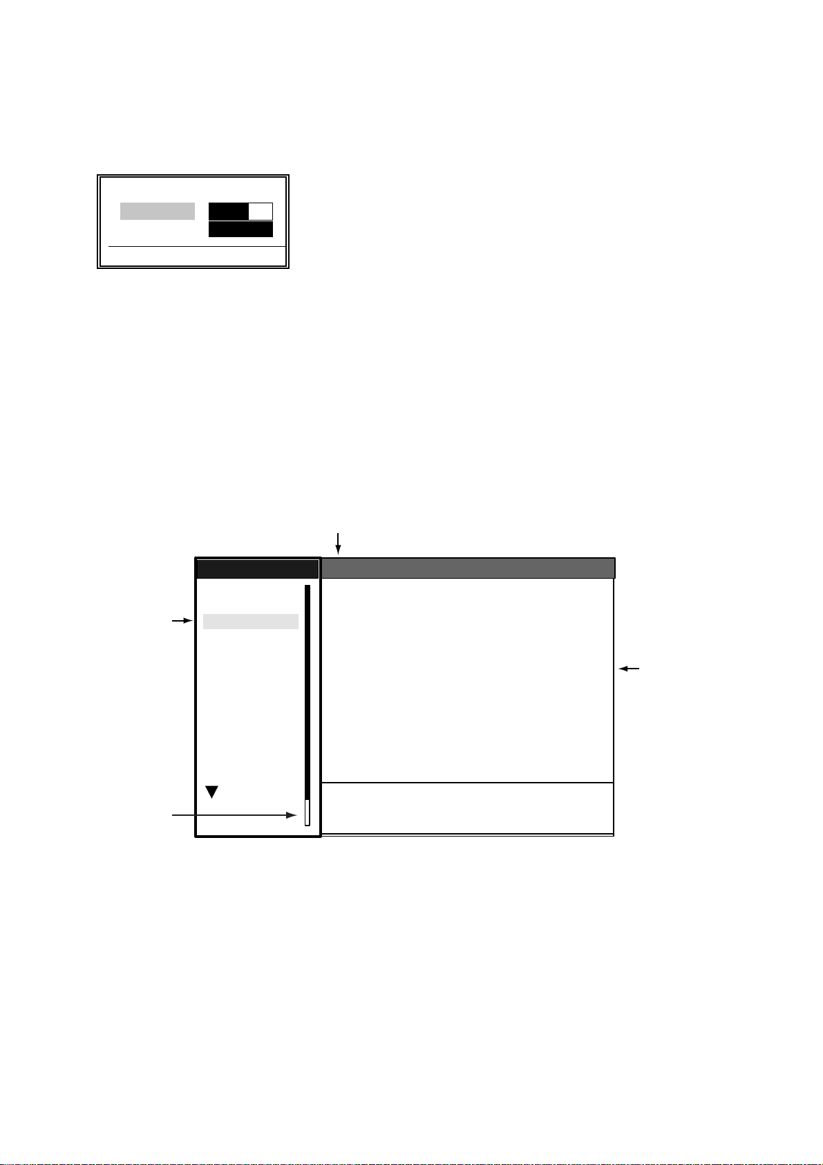
The disp lay brilliance a nd panel dim m er m ay be adju sted as follow s :
1. Press the P OWER/BRILL key mo m entarily to show t he brillianc e/ panel dialog box.
W Min Max X
Brill (1 - 15) 9 9
S
Panel (1 - 7) 7
T
[ENTER]: Close
Brilliance/panel di m m er dialog box
2. Roll the trac k ball upwa rd or downward to choos e Brill or Panel, w hichever y ou w is h to adjust.
3. Roll the trackball rightward or leftward to adjust. (You may also use the POWER/BRILL key.)
4. Press the ME NU key to close the window.
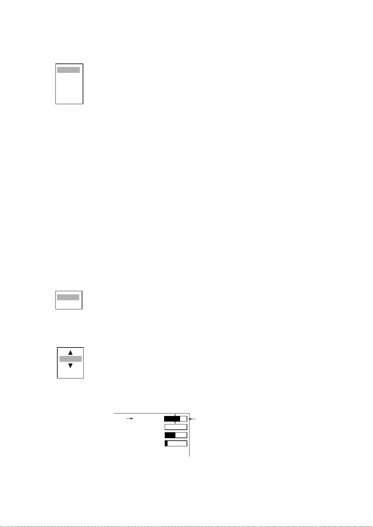
1.5 Menu Overview
Less-often used f unctions are contr olled through th e menu, which consi sts of 14 menus and 3 sub
menus. U s e t he trackball to choose it em and option as below.
1. Press the ME NU key to display the menu.
Currently selected menu
Echo
Auto Gain
Auto Sea
Auto Rain
Tune
Pulse Length
Echo Stretch
Echo Average
Noise Rejector
Interference Rejector
Auto Anti Clutter
Display-Dynamic
Display-Curve
2nd Echo Rejector
S/T / W/X: Select
[ENTER]: Enter [CANCEL/HL OFF]: Back
[MENU]: Exit
:Calm
:Moderate
:Rough
:Auto
:Short
:1
:Off
:Off
:Off
:
:Normal
:1
:Off
Menu item
and options
Menus
Menu location
indicator
Menu
Brill/Color
Display
Echo
Target Trails
Mark
Custom 1
Custom 2
Custom 3
Manual Tune
Target
ARP
AIS
GPS
System
Menu
2. Roll the trackball to choose a menu or sub menu. As you roll the trackball, the highlight in the
Menu column indicates menu currently sele cted and the menu items change according to the
menu selected.
3. Press the ENTER key to en able operat ion from cho s en m enu.
1-6
1. OPERATIONAL OVERVIEW
4. Roll the trackball to choose the menu item desired and then press the ENTER key. A window
with options for the corresponding menu item appears. For example, the window below shows
the options for Trail Color in the Target Trails menu.
Green
Red
Blue
White
Black
Target trails color options
5. Roll the trac k ball upwa rd or downward to choo s e appropriat e option.
6. Press the ENTER key to save your selection.
7. Press the ME NU key to close the menu.
Note: The menus on the IE C -type radar close automatically when t here i s no menu opera t ion for
10 seconds, as per IEC regulations. The following menus and screens however are exempt from
this rule: Alarm message, GPS se lf te s t, Satellite mo nitor, TYPE 16 messag e, D iagnostic, LC D
pattern, and Tune initial adjust. Menus do not close automatically in the “River” or “Sea” configuration.
1.6 Tuning
The radar receiver can be tuned automatically or manually, and the default tuning method is automatic. If you require manual tuning, do the following:
1. Use the RANGE key to ch oose the 48-m ile range.
2. Press the ME NU key to display the main menu.
3. Use the trackball to choose Echo and then press the ENTER key.
4. Use the tr ac k ball to choo s e Tune Mo de and then press the ENTER key.
Auto
Manual
Tuning opt ions
5. Choose Manual and then press the ENTER key.
6. Choose M anual Tune and then push the ENTER key. The window shown below appears.
2048
(0-4095)
7. Roll the trackball upward or downward to adjust the tuning, watching the tuning bar at the top
right corner. he best tuning point is where the bar graph swings maximum. The vertical bar on
the bar graph shows tuning control position; not the tuning condition.
Tuning method (Manual)
TUNE MANL
GAIN AUTO
SEA MANL
RAIN AUTO
Tuning indicator
8. Push the ENTER key to finish.
9. Press the ME NU key to close the menu.
Tuning bar
1-7

1. OPERATIONA L OVERVIEW
e
N
1.7 Presentation Modes
This radar has the following presentation modes:
Relative Motion (RM)
Head-up: Unstabilized
Head-up TB: Head-up with compass-stabilized bearing scale (True Bearing) where bearing scale
rotates with the compass reading.
Course-up: Compass-stab iliz ed relative t o s hip's orient at ion at the time of electin g c ourse-up.
North-up: Compass-stabi lize d with refe ren ce to north
True Motion (TM)
North-up: Ground or sea stabilized with compass and speed inputs
1.7.1 Choosing presentation mode
Press the MODE key consecutively to choose presentation mode desired. The presentation mode
in use appears at the top left corner on the screen.
NOTICE - Loss of gyrocompass signal: When the compass sign al is lost , "HEADING" appears
in red at the gyro readout, the presentation mode automatically becomes head-up, all ARP and
AIS targe ts and map or chart are erased. After resto ring the compass signa l, ch oose the pres entation mode with the MODE key.
1.7.2 Description of presentation modes
Head-up mode
The head-up mode is a dis play in whi c h th e line conne c ti ng own ship and the top of the display
indicates own ship's heading.
The ta rget pips are paint ed at thei r measur ed dista nces
and in their directions relative to own ship's heading.
A short line on the bearing scale is the north marker indicating heading sensor north. A failure of the heading
sensor in put will cause t he north mark er to disappear
and the read out to show ***.* a nd the message SIGNAL
MISSIN G appear s in red at th e lower-right c orner of the
screen.
orth Marker
Heading Lin
1-8
Course-up mode
1. OPERATIONAL OVERVIEW
The course-up mode is an azimuth stabilized display in which a line connecting the center with the
top of the display indicates own ship's intended
course (namely, own ship's previous heading just
before this mode has been selected).
Target p ips are painted at th eir m easured dis tances and in their directions relative to the
intended course, which is main t ained at the 0degree position. The heading line moves in accordance with ship's yawing and course change. This
mode is useful to avoid smearing of picture during
course change.
North Marker
Heading Line
Head-u p TB (True Bearing) mode
Radar ec hoes are show n in the sam e w ay as in the head-up mod e. The difference from n orm al
head-u p presentat ion lies in the orientation of t he bearing scale. The bearing scale is heading
sensor stabilized. That is, it rotates in accordance with the heading sensor signal, enabling you to
know own ship's he ading at a glan ce.
This mode is avai lable when t he radar is interf ac ed with a gyro headi ng sensor .
If the gyro heading sensor fails, the bearing scale returns to the state of head-up mode.
North-up mode
The north-up mode paints target pips at their measured distances and in their true (heading sensor) directions from own
ship, north bearing maintained at the top of the screen. The
heading line change s its direction ac c ording to the s hip's
heading. Requires heading signal.
If the compass fails, the presentati on mode changes to headup and the north marker disappears. Also , the HDG indication
shows ***.*. And the message “SIGNAL MISSING HEADING”
appear s in red at the lowe r-right corner of the screen.
North Marker
Heading Line
1-9
1. OPERATIONA L OVERVIEW
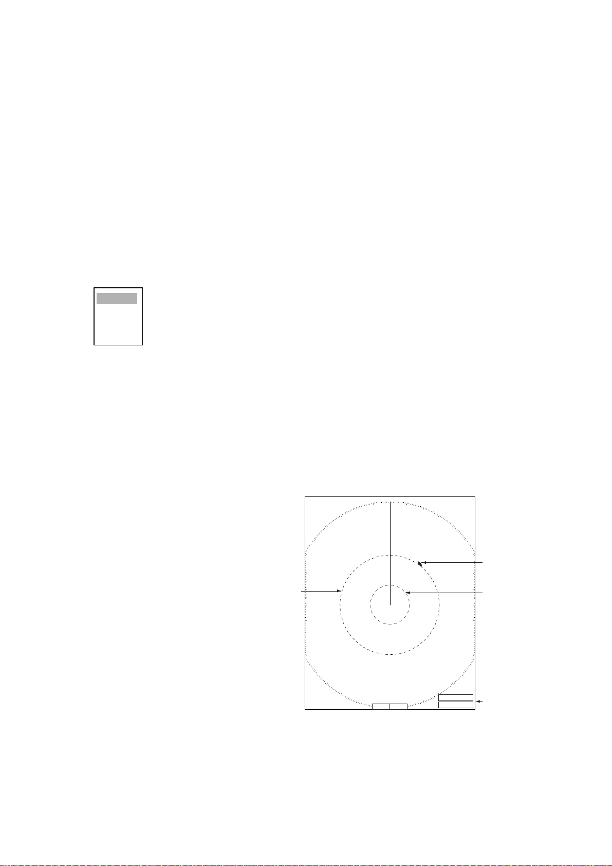
True motion mode
Own ship and other mo ving obje cts move i n accor dance with
their true courses and speed. In ground stabilized TM, all
North Marker
Heading Line
fixed targets, such as landmasses, appear as stationary
echoes. In the sea stabilized TM without set and drift inputs,
the landmass can move on the screen. Note that true motion
is not available on the 72 nm or 96 nm range scale.
When own ship reaches a point corresponding to 50% of the
radius of t he d i spl a y, own ship position i s automatically r e set
to a point of 75% radius opposite to th e ex t ension of the
heading line passing through the display center. You may
also reset the own ship symbol manually by pressing the
OFFCENTER key.
If the heading s ens or fails, the mode is changed to the headup and the north mark er disappe ars . T he H D G readout s how s * * *.* and the mes s age “SIGN AL
MISSING HEADING” appears.
Automatic resetting of own ship mark in true motion mode
North
Heading
line
290
280
270
260
250
000 010
350
340
330
320
310
300
240
230
220
210
200
marker
020
030
040
050
060
070
080
090
100
110
120
130
140
150
160
170180190
320
310
300
290
280
270
260
250
240
230
220
000 010
350
340
330
210
200
020
030
040
050
060
070
080
090
100
110
120
130
140
150
160
170180190
320
310
300
290
280
270
260
250
240
230
220
000 010
350
340
330
210
200
020
030
040
050
060
070
080
090
100
110
120
130
140
150
160
170180190
(a) True motion
is selected
(b) Own ship has reached a
point 75% of display radius
(c) Own ship is automatically
reset to 75% of radius
1.8 Choosing a Range Scale
The selected range scale, range ring interval and pulse length are shown at the upper left corner
on the screen. When a target of interest comes closer, reduc e the range scale so that it appea rs
in 50-90% of th e display radius.
Use the RANGE key to choose range desired. Hit the "+" part o f the key to raise the range; the "-
" part to lower the rang e.
1-10
1. OPERATIONAL OVERVIEW
1.9 Choosing a Pulse Length
The puls e length in use appears a t the top left po si tio n on the scre en. Appropriat e pulse lengths
are preset to individual range scales and functions keys. If you are not satisfied with the pulse
length setting on the 1.5 nm or 3 nm range, you may change it as below.
1. Press the ME NU key to open the menu.
2. Use the tr ac k ball to choo s e t he Echo menu and then press the ENTER key.
3. Use the trackball to choose Pulse Length and then press the ENTER key.
Short
Long
4. Choose Short or Long as appropriat e and then press the ENTER key.
5. Press the ME NU key to close the menu.
1.10 Adjusting the Gain (sensitivity)
The GAIN control adjusts the sensitivity of the receiver. The proper setting is such that the background noise is just visible on the screen. If you set up for too little sensitivity, weak echoes may
be missed. On the other hand excessive sensitivi ty yields too much background noise ; strong targets may be m is sed bec ause of the po or c ontrast be tween desired echo es and the back ground
noise on t he display.
1.10.1 Choosing gain adjustment method
Gain may be adjusted automatically or manually. Push the GAIN control to choose autom atic or
manual adjustment alternately. The adjustment method currently chosen is show at the top right
corner of th e s c reen. In the example bel ow t he adjustment meth od is “AUTO” .
TUNE MANL
Gain adjustment method (AUTO)
Gain adjustment method indicator
GAIN AUTO
SEA MANL
RAIN AUTO
1.10.2 Automat ic ga in ad jus tm e nt
1. Press the ME NU key to open the menu.
2. Choose th e Ec ho menumenu and t hen press the ENTER key.
3. Choose Auto Gain an d t hen press th e ENTER key.
Rough
Moderate
Calm
4. Choose the sea condition which best matches the auto gain options.
5. Press the ENTER key followed by the MENU key to close the menu.
1-11
1. OPERATIONA L OVERVIEW
1.10.3 Manual gain adjustment
1. Push the GAIN control to show “GAIN MANL” as the gain adjustment method.
2. Rotate the GAIN control to adjust the gain. Adjust the contro l so background noise is just visible
on the screen.
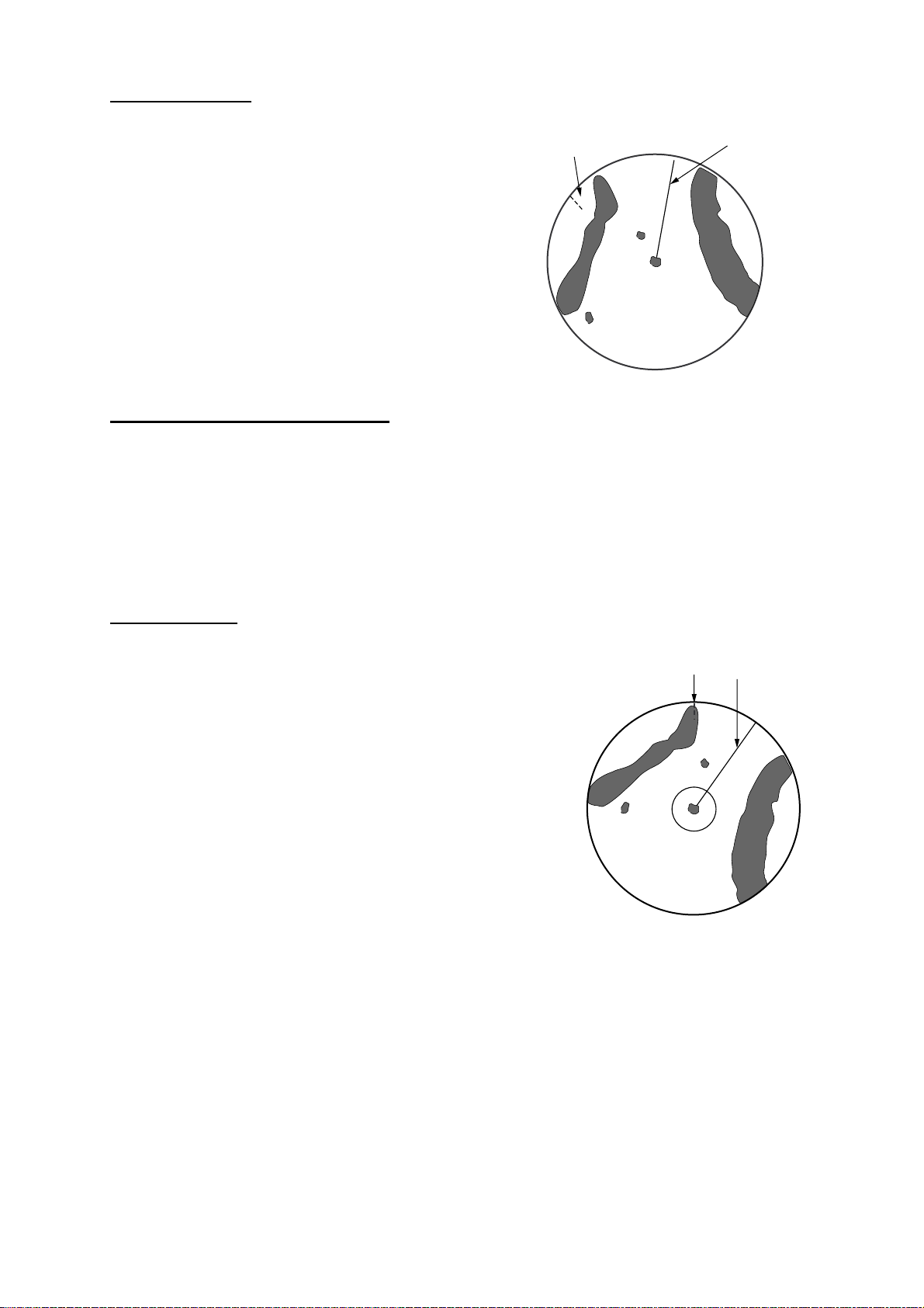
1.11 Suppressing Sea Clutter
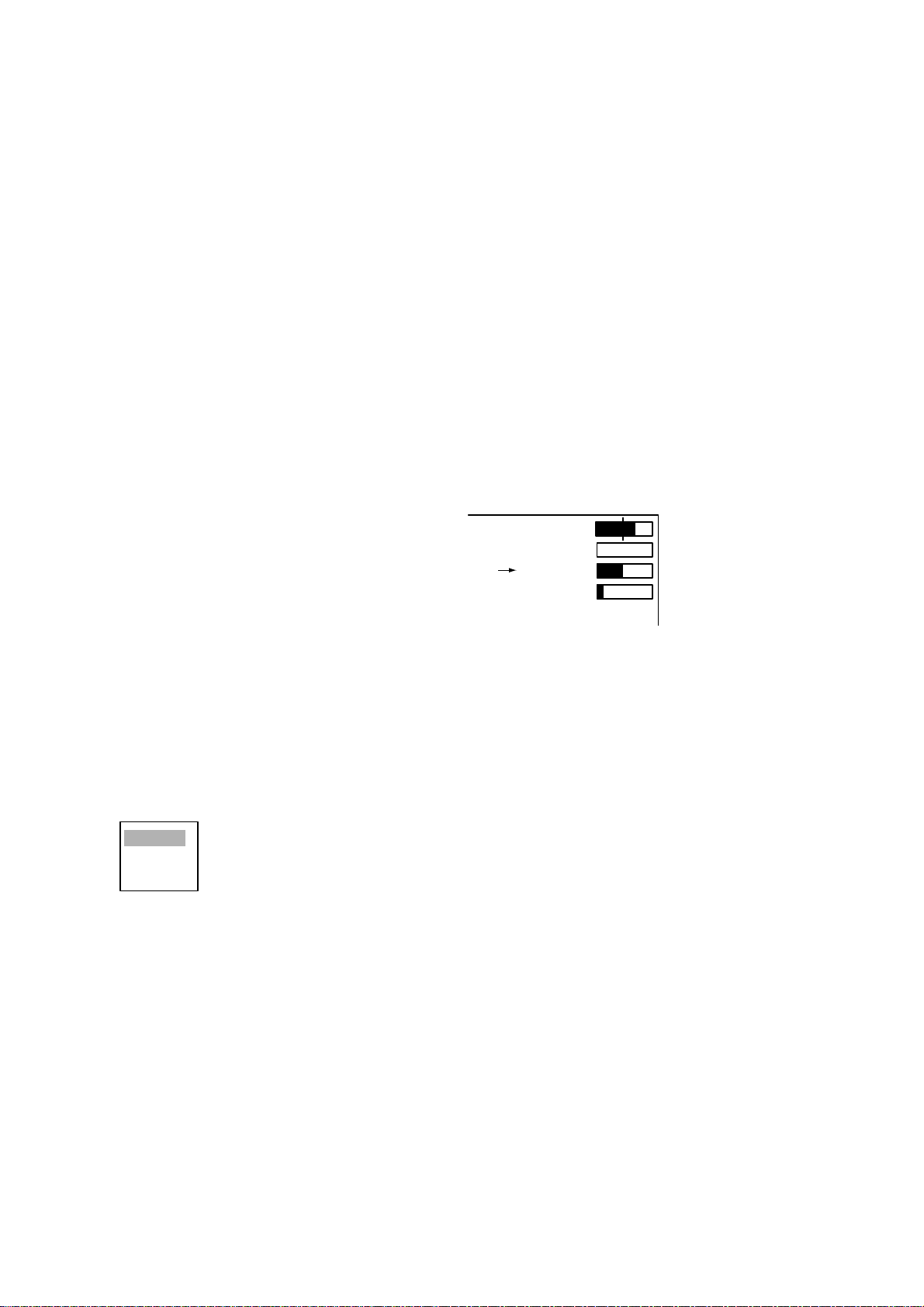
Echoes from waves cover the central part o f the display wi th random signals k nown as sea clutter .
The higher the wave s , a nd t he higher th e antenna ab ov e the water , the further th e c lutter will
extend. When sea clutter masks the picture, use the SEA control to suppress the clutter, either
manually or automatically.
1.11.1 Choosing sea clutter adjustment method
Sea clutter may be adjusted automatically or manually. Push the SEA control to choose automatic
or manual adjustment alt ernately. The adjustment method curre ntly chosen is show at the top right
corner of th e s cr een. In the example bel ow t he s ea clutter a djustment m et hod is “MAN L”
(manual).”
TUNE MANL
GAIN AUTO
SEA adjustment method (MANUAL)
SEA indicator
SEA MANL
RAIN AUTO
1.11.2 Automatic sea clutter adjustment
1. Press the ME NU key to open the menu.
2. Choose th e Ec ho menu a nd then pres s th e ENTER key.
3. Choose Auto Sea and th en press the ENTER key.
Rough
Moderate
Calm
4. Choose the sea condition which best matches the Auto Sea options.
5. Press the ENTER key followed by the MENU key to close the menu.
1-12
1. OPERATIONAL OVERVIEW
1.11.3 Manual sea clutter adjustment
1. Push the SEA control to show “SEA MANL” as the SEA adjustment method.
2. Rotate the SEA contro l to suppress sea clutter.
The proper setting of the SEA control sh oul d be su ch th at th e clutter is b r oken up i n to sma ll dots,
and small targets become dis tinguishabl e. If the setti ng i s set too low, targ ets wil l be h idden in t he
clutter, while if the setting is too high, both sea clutter and targets will disappear from the display.
In most cases adjust the control until clutter has disappeared to leeward, but a little is still visible
windward.
Sea clutter at
screen center
SEA adjusted;
sea clutter suppressed
How to adjust the SEA control
1.12 Suppressing Rain Clutter
The vertical beamwidth of the scanner is designed to see surface targets even when the ship is
rolling. However, by this design the unit will also detect rain clutter (rain, snow, or hail) in the same
manner as normal targets.
The RAIN control adjusts the receiver sensitivity as the SEA control do es but rathe r in a longer
time period (longer range). The hig her the se tting the gr eater the anti-cl utter effe ct. When echoes
from precipitation mask solid targets, adjust the control to split up these unwanted echoes into a
speckled pattern, making recognition of solid targets easier.
1.12.1 Choosing rain clutter adjustment method
Rain clutter may be adjusted automatically or manually. Push the RAIN control to choose auto-
matic or m anual adjus t m ent altern at ely . T he adjustm ent m et hod curre nt ly ch os en is show a t the
top right corner of the s c reen. In the example be low t he adjustment meth od is “AUTO .”
RAIN adjustment method (AUTO)
RAIN ind i cator
TUNE MANL
GAIN AUTO
SEA MANL
RAIN AUTO
1-13
1. OPERATIONA L OVERVIEW
1.12.2 Automatic rain clutter adjustment
1. Press the ME NU key to open the menu.
2. Choose th e Ec ho menu a nd then pres s th e ENTER key.
3. Choose Auto Rain and then press the ENT ER k ey.
Rough
Moderate
Calm
4. Choose the sea condition which best matches the Auto Rain options.
5. Press the ENTER key followed by the MENU key to close the menu.
1.12.3 Manual rain clutter adjustment
1. Push the A/C RAIN control to s how “R AIN MANL” as the RA IN adjustme nt m et hod.
2. Rotate the A/C RAIN control to suppress the rain clutter.
Rain clutter at RAIN control adjusted
screen center
How to adjust the A/C RAIN control
1.13 Automatic Suppress ion of Sea and Rain Clutters
Both sea and rain clutte rs may be adj ust ed auto matica l l y. When thi s fe atu r e is a cti ve it overri d es
the SEA and RAIN controls.
1. Press the ME NU key to open the menu.
2. Choose th e Ec ho menu a nd then pres s th e ENTER key.
3. Choose Auto Anti Clutter and then press the ENTER key.
Off
On
4. Choose Off or On as appro priate.
5. Press the ENTER key followed by the MENU key to close the menu.
1-14

1. OPERATIONAL OVERVIEW
or
1.14 Cursor
The cur s or funct ions to ft he range and beari ng to a tar get or lat ititude and lon gitude positi on of a
target, and the default function is range and bearing. Rol l the trackbal l to position the curso r and
then read cursor data at the screen bottom.
3
0.5
NM
+
+
Curs
+ 110.1°R 2.525 NM
Cursor data
(L/L or range and bearing)
Cursor da t a
1.14.1 Cursor data
Cursor data can be shown as latitude and longitude or range and bearing to the cursor.
1. Press the ME NU key to open the menu.
2. Choose th e M ark menu and then pre s s t he ENTER key.
3. Choose Brg/Rng or Lat/Long as appropri at e.
4. Press the ENTER key followed by the MENU key to close the menu.
1-15
1. OPERATIONA L OVERVIEW
1.15 Interference Rejector
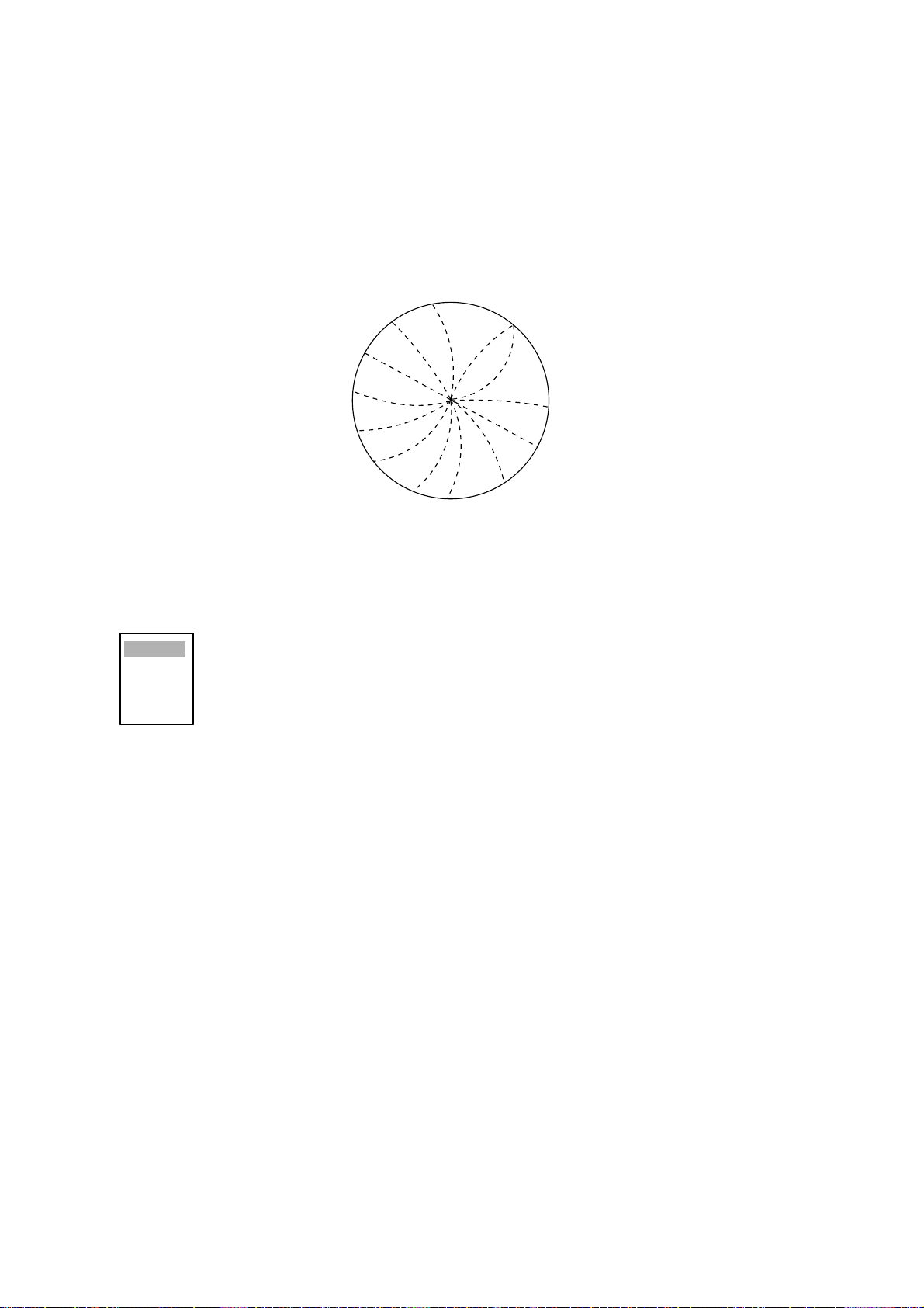
Mutual ra dar interference may oc c ur in the vicinity of another shipborne r ada r operating in the
same frequency band. It is seen on the screen as a number of bright spikes either in irregular patterns or in t he fo rm of usu all y curv ed sp oke- lik e dott ed li nes ex tendi ng fr om the cent er to the edg e
of the picture. Activating the interference rejector circuit can reduce this type of interference.
The interference rejector is a kind of signal correlation circuit. It compares the received signals
over s ucces sive t ransmiss ions and supp resses random ly occ urring signa ls. The re are t hree l evels
of interference reje c tio n depending on the number of trans m is s ions that ar e c orrelated.
Interference
1. Press the ME NU key to open the menu.
2. Choose th e Ec ho menu a nd then pres s th e ENTER key.
3. Choose In te rf erence Rejector and th en press the ENTER key.
Off
Low
Med
High
4. Choose Off, Low, Med or High as appropriate and then press the ENTER key.
5. Press the ME NU key to close the menu.
Be sure to turn off the interference rejector when no interference exists so as not to miss small
targets.
1-16
1. OPERATIONAL OVERVIEW
1.16 Measuring the Range to a Target
The range to a target may be measured three ways: with the fixed range rings, with the cursor (if
set to measure range and bearing), or with the VRM.
Use the fixed range rings to obtain a rough estimate of the range to a target. They are the concentric solid circles about own ship, or the sweep origin. The number of rings is automatically determined by the selected range scale and their interval is displayed at the upper-left position of the
screen. Count the number of rings between the center of the display and the target. Check the
range rin g int erval and ju dge the dist anc e of the ech o fr om t he inner edge of the nearest ring.
1.16.1 Adjusting range ring brilliance
1. Press the ME NU key to open the menu.
2. Choose th e Brill/Color m enu and the n press the ENTER key.
3. Choose R ange Rings Brill and the n press the ENTER key.
Off
Low
Medium
High
4. Choose appropriat e brilliance a nd then press th e ENTER key.
5. Press the ME NU key to close the menu.
1.16.2 Measuring range by the variable range marker (VRM)
There ar e two VR Ms, No. 1 and No . 2, wh ich ap pear as dash ed rin gs so th at you c an dis cri mina te
them from the fixed range rings. The two VRMs can be distinguished from each other by different
lengths of dashes.
1. Press the VRM key to display e ither
of the VRMs. Suc cessively pressing
the VRM key toggles the active
VRM between No. 1 and No. 2. The
currently active marker is enclosed
with >.....<.
2. Operate t he Trackball to align the
active variable range marker with
the inner edge of the target of
interest an d read i ts distance at the
lower-right corner of the screen.
Each VRM remains at the same
geogra phical distance when you
operate t he RANGE key. This
means that the apparent radius of
the VRM ri ng ch ange s in pr oport ion
to the selected range scale.
3. Press the VRM key to erase each
VRM.
VRM1
+
VRM1>0.007NM<
+ 96.8°R 0.338 NM
VRM2 0.140
How to measure range with VRMs
Target
VRM2
VRM1, VRM2
NM
range
1-17
1. OPERATIONA L OVERVIEW
1.16.3 Choosing VRM unit
The unit of measurement used by the VRM can be selected to nau ti ca l mil es, kilo meter s, sta tu te
miles or kilometers/yard.
1. Press the ME NU key to open the menu.
2. Choose th e M ark menu and then press the ENTER key.
3. Choose VR M U nit and the n press the ENTER key.
nm
km
sm
kyd
4. Choose des ired unit an d t hen press th e ENTER key.
5. Press the M ENU key to cl os e t he menu.
1.17 Measuring the Bearing to a Target
Use the Electronic Bearing Lines (EBLs) to take bearings of targets. There are two EBLs, No. 1
and No. 2. Each EBL is a straight dashed line extending out from the own ship position up to the
circ um ference of the r adar picture. Th e f ine dashed lin e i s t he No. 1 EB L and the co arse das hed
one is the No. 2 EBL.
1. Press the EBL key to display either of the EBLs. Successively pressing the EBL key toggles
the active EBL between No. 1 and No. 2. The currently active marker is enclosed with >.....<.
2. Operate the Trackball to bisect the target of interest with the EBL and read its distance at the
lower-left corner of the screen.
3. Press the EBL key to erase each EBL.
EBL2
EBL1
+
1-18
EBL1, EBL2
EBL1>270.0°R<
EBL2 0.45.0°
R
+ 96.8°R 0.338 NM
bearing
How to measure the bearing to a target with the EBL

1. OPERATIONAL OVERVIEW
N
E
4
1.17.1 EBL reference
The EBL readou t is affi x ed by "R." (rel ative) if it i s relative to own s hip's he ading, "T." ( t rue) if i t is
referenced to the north. You may choose relative or true in the head-up modes; in all other modes
it is always TRUE.
1. Press the ME NU key to open the menu.
2. Choose th e M ark menu and then pre s s t he ENTER key.
3. Choose EBL Reference and then press the ENTER key.
Relative
True
4. Choose R elative or True as appropriate and then pre s s the ENTER key.
5. Press the ME NU key to close the menu.
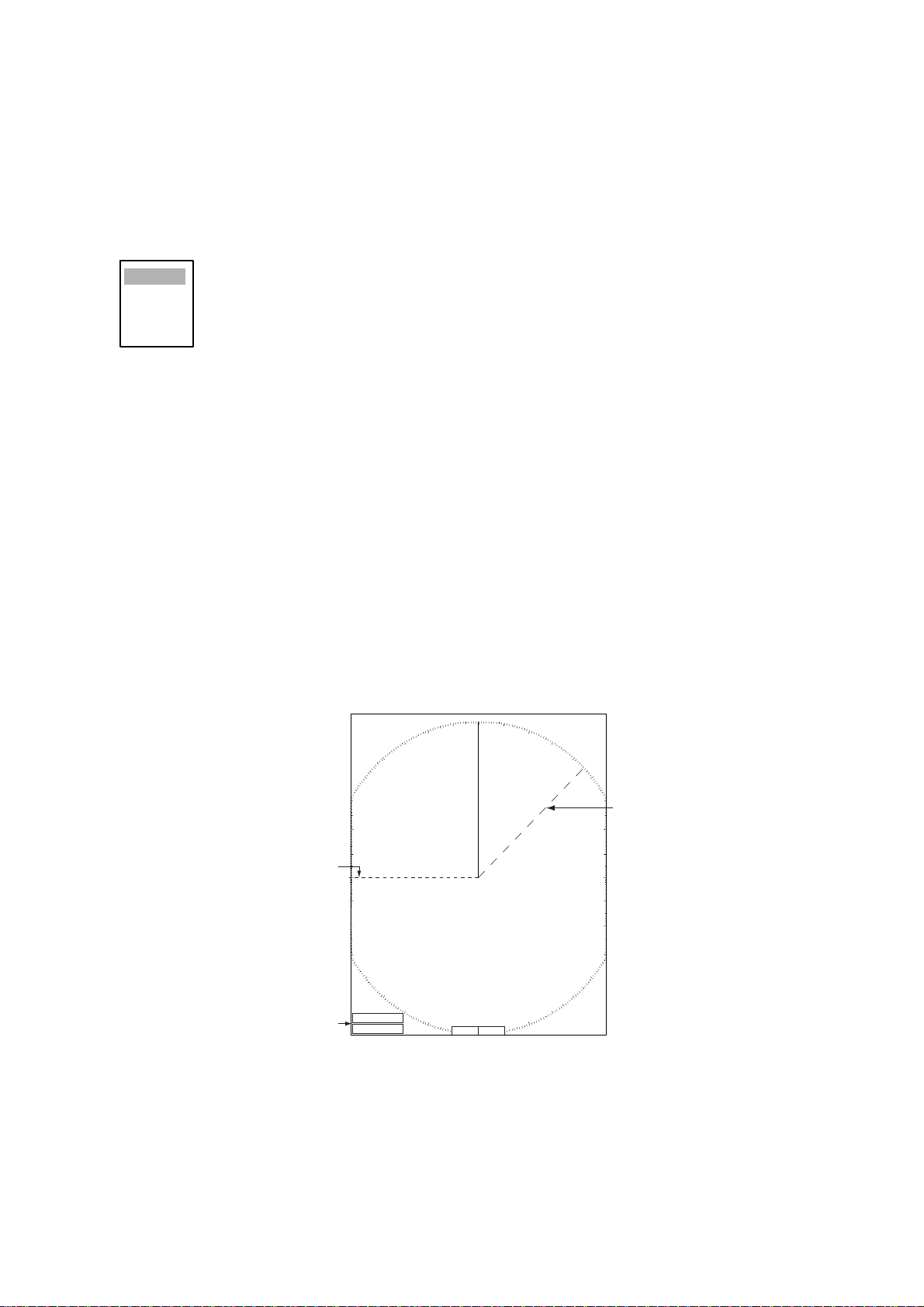
1.18 Measuring the Range and Bearing Between Two
Targets
You may shift the origin of the EBL to measure the range and bearing between two targets.
1. Press the EBL key to circumscribe the bearing indication of EBL1 or EBL2 with a dashed
rectangle.
2. Drag the EBL to the locati on of one t arget and t hen press th e ENTER key to anchor the EBL.
3. Roll the trackball to shift the range marker to the location of the other target.
4. Read the bearing and range indic at ions at the bottom of th e s c reen.
No. 2
EBL
Range
Marker
R2
VRM1
>0.500NM<
0.980NM
VRM2
o. 1
BL
EBL1
EBL2
Range
Marker
>140.0°R<
°
R
335.2
Target 1
EBL
origin
+
Target 2
Target 4
Target 3
+
Range/bearing
between targets 1 and 2
Range/bearing
between targets 3 and
Measuring range and bearing between two target with the EBL
To return the origin of the EBL to the screen center, press the EBL key to circumscribe the indication of that the EBL with a solid rectangle.
1-19
 Loading...