

Furuno USA 9ZWRTR079A, 9ZWRTR078A Users Manual

MARINE RADAR/ARPA
FAR-2117/2127/2817/2827
FAR-2117-BB/2127-BB
Installation Manual
TABLE OF CONTENTS
SAFETY IINSTRUCTIONS..................... i
EQUIPMENT LISTS...............................iii
SYSTEM CONFIGURATION .................vi
1. MOUNTING.....................................1-1
1.1 Antenna Unit.................................1-1
1.2 Monitor Unit..................................1-6
1.3 Control Unit................................1-10
1.4 Processor Unit............................1-15
2. WIRING........................................2-1
2.1 Interconnection.............................2-1
2.2 Antenna Unit.................................2-2
2.3 Monitor Unit..................................2-6
2.4 Processor Unit..............................2-7
2.5 Changing AC Power Specification of
Comply with MSC.192(79)
3.7 Dual Radar Display
(non IMO-type only) ..................3-16
4. INSTALLING OPTIONAL
EQUIPMENT................................ 4-1
4.1 Gyro Converter GC-10.................4-1
4.2
Memory Card Interface Unit
4.3 DVI-RGB Conversion Kit
(for VDR connection) ..................4-12
4.4 Performance Monitor PM-31......4-15
4.5 BNC Connector Converter .........4-17
4.6 Junction Box...............................4-18
5. INPUT/OUTPUT DATA................ 5-1
INSTALLATION MATERIALS,
ACCESSORIES,SPARE PARTS........A-1
OUTLINE DRAWINGS ......................D-1
..............4-9
Processor Unit ..........................2-12
3. SETTING AND ADJUSTMENT ....3-1
3.1 DIP Switch Setting .......................3-1
3.2 Initializing Tuning..........................3-2
3.3 Heading Alignment.......................3-3
3.4 Adjustment Sweep Timing............3-6
Suppressing Main Bang
3.5
3.6 Other Settings..............................3-8
All brand and product names are trademarks, registered trademarks or
service marks of their respective holders.
...................3-7
www.furuno.co.jp
INTERCONNECTION DIAGRAMS ...S-1

Thepaperusedinthismanual
9‑52Ashihara‑cho,
Fax:
A:JAN
2004
.
Pub.No.
(
)
*
00014745418
**00014745418
*
Nishinomiya,662‑8580,JAPAN
Telephone: +81‑(0)798‑65‑2111
+81‑(0)798‑65‑4200
iselementalchlorinefree.
・FURUNOAuthorizedDistributor/Dealer
Allrightsreserved.
HIMA
FAR‑2117/27/2817/27
PrintedinJapan
K1:FEB.25,2011
IME‑35190‑K1
*00014745418**00014745418*
*00014745418*

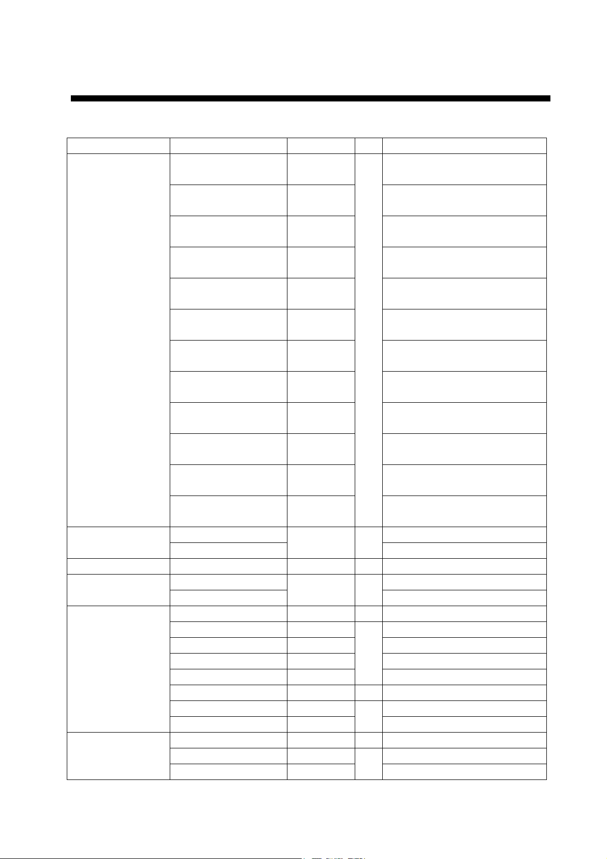
100W/m250W/m210W/m
2
XN-12AF 0.3 m 1.2m 3.7 m
XN-20AF 0.1 m 0.7 m 2.2 m
XN-24AF 0.1 m 0.4 m 1.5 m
XN-12AF 0.9 m 2.6 m 9.0 m
XN-20AF 0.5 m 1.7 m 4.6 m
XN-24AF 0.2 m 1.0 m 3.3 m
MAF1565N
RTR-078A
(X-12 kw)
FAR-2817/2117
FAR-2827/2127
RTR-079A
(X-25 kw)
MG5436
SAFETY INSTRUCTIONS
The operator and installer must read the applicable safety instructions before attempting to
install or operate the equipment.
Indicates a potentially hazardous situation which, if not avoided,
DANGER
WARNING
CAUTION
Warning, Caution
will result in death or serious injury.
Indicates a potentially hazardous situation which, if not avoided,
could result in death or serious injury.
Indicates a potentially hazardous situation which, if not avoided,
can result in minor or moderate injury.
Prohibitive Action
Mandatory Action
DANGER
Wear a safety belt and hard hat when working on the antenna unit.
Serious injury or death can result if someone falls from the radar antenna
mast.
WARNING
Radio Frequency Radiation Hazard
The radar antenna emits electromagnetic radio frequency (RF) energy which can be harmful,
particularly to your eyes. Never look directly into the antenna aperture from a close distance
while the radar ius in operation or eexpose yourself to the transmitting antenna at a close
distance. Distances at which RF radiation level of 100, 50 and 10 W/m are given in the table
below.
Note: If the antenna unit is installed at a close distance in front of the wheel house, your
administration may require halt of transmission within a certain sector of antenna revolution.
This is possible. Ask your FURUNO representive or dealer to provide this feature.
1
Model Transceiver Magnetron Antenna
*
2
*
:
XN12AF: 4 ft, XN20AF: 6.5 ft, XN24AF: 8 ft
i
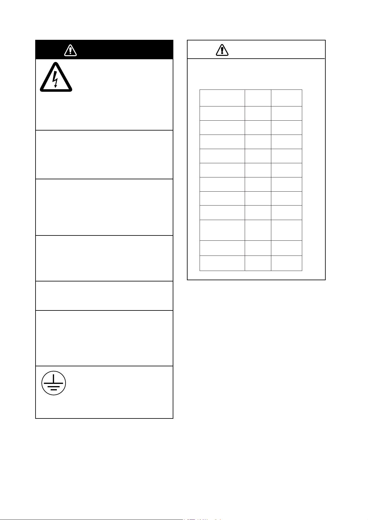
WARNING
CAUTION
Do not open the equipment
unless totally familiar with
electrical circuits and
service manual.
ELECTRICAL
SHOCK
HAZARD
Only qualified personnel
should work inside the
equipment.
Construct a suitable service platform
from which to install the antenna unit.
Serious injury or death can result if someone falls from the radar antenna mast.
Turn off the power at the mains switchboard before beginning the installation.
Fire, electrical shock or serious injury can
result if the power is left on or is applied
while the equipment is being installed.
Be sure that the power supply is
compatible with the voltage rating of
the equipment.
Connection of an incorrect power supply
can cause fire or damage the equipment .
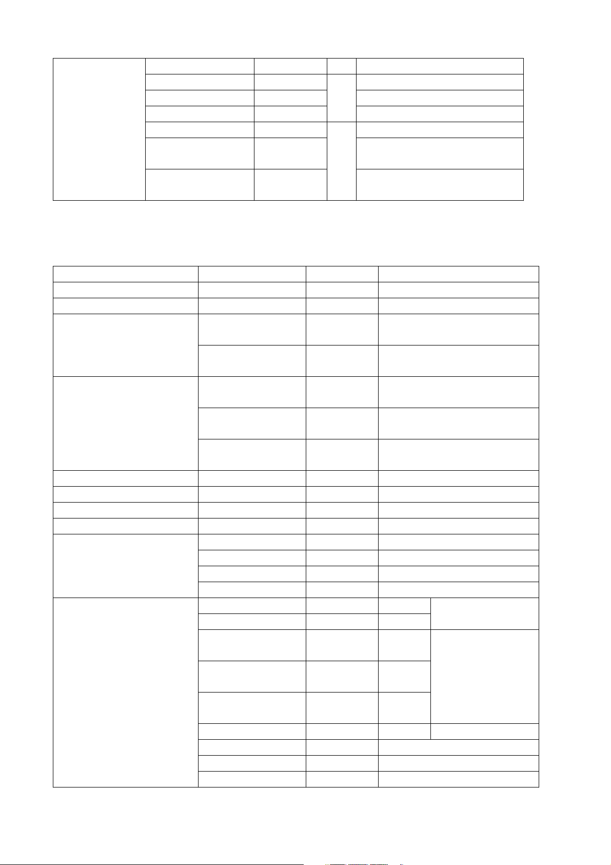
Observe the following compass safe
distances to prevent deviation of a
magnetic compass:
Steering
compass
0.70 m
0.60 m
Antenna Unit
(12 kw)
Antenna Unit
(25 kw)
Monitor Unit
(MU-201CR)
Monitor Unit
(MU-231CR)
Processor
Unit (RPU-013)
Control Unit
(RCU-014)
Control Unit
(RCU-015)
Control Unit
(RCU-016)
Memory Card
Interface Unit
(CU-200)
Junction Box
(RJB-001)
Switching Hub
(HUB-100)
Standard
compass
2.15 m 1.40 m
2.05 m 1.30 m
1.55 m 1.00 m
1.85 m 1.20 m
1.35 m 0.85 m
0.30 m 0.30 m
0.95 m 0.60 m
0.65 m 0.45 m
0.90 m 0.60 m
1.10 m
1.00 m
Use only the specified power cable.
Fire or damage to the equipment can result
if a different cable is used.
Do not install the monitor unit,
processor unit or control unit where
they may get wet from rain or
water splash.
Water in the units can result in fire,
electrical shock, or damage the equipment.
Attach securely protective
earth to the ship's body.
The protective earth
(grounding) is required to the
AC power supply to prevent
electrical shock.
ii
EQUIPMENT LISTS
Standard Supply
Name Type Code No. Qty Remarks
XN12AF-RSB096-078A -
XN12AF-RSB097-078A -
XN20AF-RSB096-078A -
XN20AF-RSB097-078A -
XN24AF-RSB096-078A -
XN24AF-RSB097-078A -
Antenna Unit
XN12AF-RSB096-079A -
XN12AF-RSB097-079A -
XN20AF-RSB096-079A -
XN20AF-RSB097-079A -
XN24AF-RSB096-079A -
XN24AF-RSB097-079A -
Monitor Unit
Processor Unit RPU-013 - 1
Control Unit
Installation Materials
Accessories
MU-201CR For FAR-2117/2127
MU-231CR
RCU-014 Standard type
RCU-015
CP03-25601 008-535-550 1 For antenna unit
CP03-25700 000-080-435 15 m signal cable RW-9600
CP03-25710 000-080-436 30 m signal cable RW-9600
CP03-25720 000-080-437 50 m signal cable RW-9600
CP03-25730 000-082-191
CP03-25800 000-080-434 1 Cable assy. for monitor unit
CP03-25602 008-535-940 For RPU-013, AC set
CP03-25603 008-535-950
FP03-09810 008-536-010 1 For monitor unit
FP03-09850 008-535-610 For RCU-014
FP03-09860 008-535-690
- 1
- 1
1
1
1
1
FAR-2117/2117-BB/2817, 24 rpm,
1200 mm, W/CP03-24201
FAR-2117/2117-BB/2817, 42 rpm,
1200 mm, W/CP03-24201
FAR-2117/2117-BB/2817, 24 rpm,
2000 mm, W/CP03-19101
FAR-2117/2117-BB/2817, 42 rpm,
2000 mm, W/CP03-19101
FAR-2117/2117-BB/2817, 24 rpm,
2400 mm, W/CP03-19101
FAR-2117/2117-BB/2817, 42 rpm,
2400 mm, W/CP03-19101
FAR-2127/2127-BB/2827, 24 rpm,
1200 mm, W/CP03-24201
FAR-2127/2127-BB/2827, 42 rpm,
1200 mm, W/CP03-24201
FAR-2127/2127-BB/2827, 24 rpm,
2000 mm, W/CP03-19101
FAR-2127/2127-BB/2827, 42 rpm,
2000 mm, W/CP03-19101
FAR-2127/2127-BB/2827, 24 rpm,
2400 mm, W/CP03-19101
FAR-2127/2127-BB/2827, 42 rpm,
2400 mm, W/CP03-19101
For FAR-2817/2827
Trackball type
40 m signal cable RW-9600
For RPU-013, DC set
For RCU-015/016
iii
SP03-12501 008-485-360 1 For antenna unit
SP03-14404 008-535-910 For processor unit 100 VAC set
1
For processor unit 24 VDC set
For monitor unit, DC set,
1
MU-201CR
For monitor unit, DC set,
MU-231CR
Spare Parts
SP03-14405 008-535-920 For processor unit 220 VAC set
SP03-14406 008-535-930
SP03-14401 008-535-990 For monitor unit AC set
SP03-03900 000-081-063
SP03-14402 008-536-000
Optional Equipment
Name Type Code No. Remarks
Gyro Converter GC-10-2 000-080-440 See chapter 4.
Performance Monitor PM-31 000-080-438 Mandatory for IMO radar
RU-1803 -
Transformer Unit
RU-3305 -
RU-3424 -
Rectifier
Memory Card Interface Unit CU-200-FAR 000-081-568 W/CP03-27430, See chapter 4.
External Buzzer OP03-21 000-030-097
Control Unit RCU-016 - Remote type, W/FP03-09860
RAM Card 00RAM08MC-005 004-376-740 8 MB
DVI-RGB Conversion Kit
Cable Assy.
RU-1746B-2 -
RU-3423 -
OP03-180-1 008-545-590 Mounted at factory
OP03-180-2 008-536-070 Mounted in field. See chapter 4.
OP03-180-3 008-545-610 Mounted in console at factory.
OP03-180-4 008-545-600 Mounted in console in field.
XH10P-W-6P L=20M 000-149-748 20 m
XH10P-W-6P L=30M 000-149-749 30 m
XH10P-W-5P-A
L=10M
XH10P-W-5P-A
L=20M
XH10P-W-5P-A
L=30M
DVI-D/D S-LINK 10M
S03-9-5 008-206-640 For external radar, 5 m, 8-8P
S03-9-10 008-206-650 For external radar, 10 m, 8-8P
S03-9-15 008-209-160 For external radar, 15 m, 8-8P
000-149-050 10 m
000-149-051 20 m
000-149-052 30 m
000-150-200
Converts 440 VAC to 100 VAC,
for processor unit
Converts 110/115/220/230 VAC
to 100 VAC, for de-icer
115/230 VAC to 24 VDC, for
processor unit (25 kW)
115/230 VAC to 24 VDC, for
processor unit (12 kW)
100/110/115/220/230 VAC to 24
VDC, for monitor unit
Between control &
processor unit
Between control
units
10 m Monitor-Processor
iv

OP03-28900 000-082-658
LAN Cable Kit (with armor)
Accessories
Hand Grip FP03-09840 008-535-570 For monitor unit
Dust Cover
Hood
Clamp Plate OP03-182 008-535-620 For RCU-014
Flush Mount Kit
Coupling Pedestal
BNC Connector Converter DSUB-BNC-1 000-148-528 For VDR
Junction Box RJB-001 Desktop Mount Kit FP03-10201 008-539-530 For CU-200
Console Mount Kit FP03-10202 008-539-540 For CU-200
Switching Hub HUB-100 - See manual of HUB-100.
OP03-28910 000-082-629
OP03-28920 000-082-660
FP03-09820 008-535-560 Hanger assy. for MU-201CR
FP03-09830 008-536-020 Hanger assy. for MU-231CR
03-163-1201 100-307-260 For MU-201CR
03-163-2101 100-307-270 For MU-231CR
FP03-11500 001-020-090 For MU-201CR
FP03-11000 008-571-680 For MU-231CR
FP03-09870 008-535-630
OP03-198 001-008-050
OP03-183 008-535-640 For RCU-014&MU-201CR
OP03-184 008-535-650 For RCU-014& MU-231CR
OP03-185 008-535-660 For RCU-014
FP03-11010 001-033-140 For MU-231CR display unit Slim Hood
FP03-11510 001-034-390 For MU-201CR display unit
About the category sticker
FR-FTPC-CY
10 m
FR-FTPC-CY
20 m
FR-FTPC-CY
30 m
For control unit
RCU-016/014/015
For more than 100m
antenna cable
Modular
connection
MPS588-C,
2 pcs.
This radar meets the requirements in IEC62388 (Marine navigation and
radiocommunication equipment and systems – Shipborne radar – Performance
requirements, method of testing and required test results)
Check the appropriate box on the sticker which is pre-attached on the processor unit,
according to your radar’s specification. Refer to the table shown below to confirm your
category.
Category Radar type ANT. rotation speed
CAT1
CAT1H FAR-2817, FAR-2827, FAR-2837S HSC
CAT2
CAT2H
FAR-2817, FAR-2827, FAR-2837S,
FAR-2827W, FAR-2837SW
FR-2117/BB, FAR-2127/BB,
FAR-2137S/BB
FAR-2117/BB, FAR-2127/BB,
FAR-2137S/BB
Normal speed
Normal speed
HSC
v
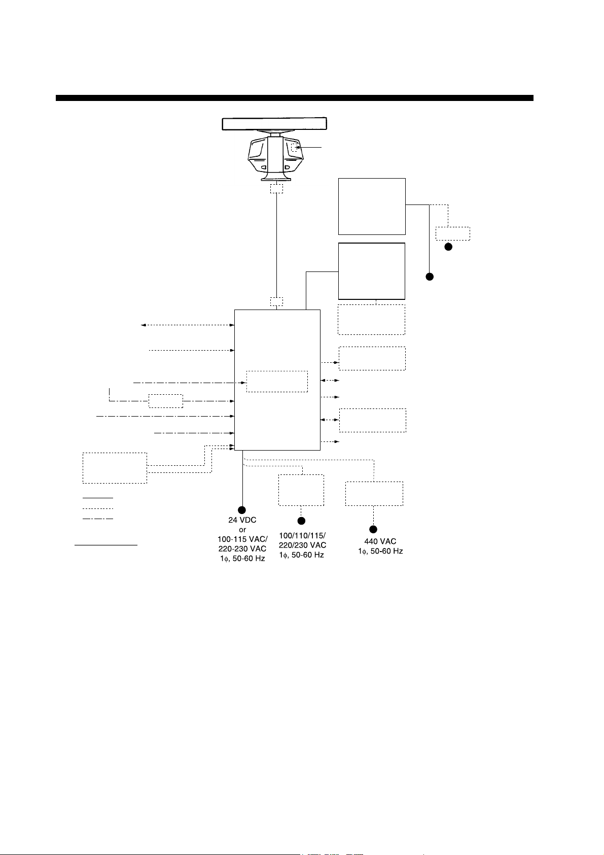
SYSTEM CONFIGURATION
Performance Monitor
ANTENNA UNIT
FAR-2117/2817: XN12AF-RSB-096-078A
XN12AF-RSB-097-078A
XN20AF-RSB-096-078A
XN20AF-RSB-097-078A
XN24AF-RSB-096-078A
XN24AF-RSB-097-078A
FAR-2127/2827: XN12AF-RSB-096-079A
XN12AF-RSB-097-079A
XN20AF-RSB-096-079A
XN20AF-RSB-097-079A
XN24AF-RSB-096-079A
XN24AF-RSB-097-079A
1)
EPFS
(Navigator)
2)
SDME
(Speed Log)
Gyrocompass
IEC-61162 Serial Data
(Input/Output)
IEC-61162 Serial Data
(Input)
3)
AD-100
AIS
Track Control Unit
MEMORY CARD
INTERFACE UNIT
CU- 200-FAR
: Standard
: Option
: Dockyard supply
JB
**
JB
**
PROCESSOR UNIT
RPU-013
Gyro Converter
GC-10
DC spec
Rectifier
RU-3424
RU-1746B-2
MONITOR UNIT
MU-201CR (CAT1)
(FAR-2117/2127)
or
MU-231CR (CAT2)
(FAR-2817/2827)
CONTROL UNIT
RCU-014
(Standard)
or
RCU-015
(Trackball)
Control Unit
RCU-016
(Remote)
Sub Display
Alarm***
VDR
Switching HUB
HUB-100
External Monitor
AC spec
Transformer Unit
RU-1803
*
24 VDC
RU-3423
100/110/115
220/230 VA C
24 VDC
or
100-230 VA C
Category of Units
Antenna Unit: Exposed to weather
All other units: Protected from weather
1) Connect the EPFS which is approved in accordance with the requirements of the IMO in
resolution MSC.112(73) is used.
2) Connect the SDME which is approved in accordance with the requirements of IMO in
resolution MSC.96(72) is used.
3) Use the gyrocompass having an update rate that is adequate for the ship’s rate of turn.
*: For FAR-2117-BB/2127-BB a monitor unit is prepared by user. See page 1-6.
These monitors have been approved by the IMO, MU-201CR for CAT 2, MU-231CR for
CAT 1. If a different monitor is to be used, its effective diameter must meet the applicable
Category requirements: CAT 1: effective diameter 320 mm or higher, CAT 2: effective
diameter 250 mm or higher. Refer to their operator’s manuals for details.
**: Junction boxes are required for more than 100 m antenna cable.
***: Contact output for Alarm
(Load current) 120 mA (Polarity) No.1, 2: Normally Close, No.3, 4: Normally Open
Serial I/O for alarm is also possible, which complies with IEC 61162-1.
vi
1. MOUNTING
NOTICE
Do not apply paint, anti-corrosive sealant
or contact spray to coating or plastic
parts of the equipment.
Those items contain organic solvents that
can damage coating and plastic parts,
especially plastic connectors.
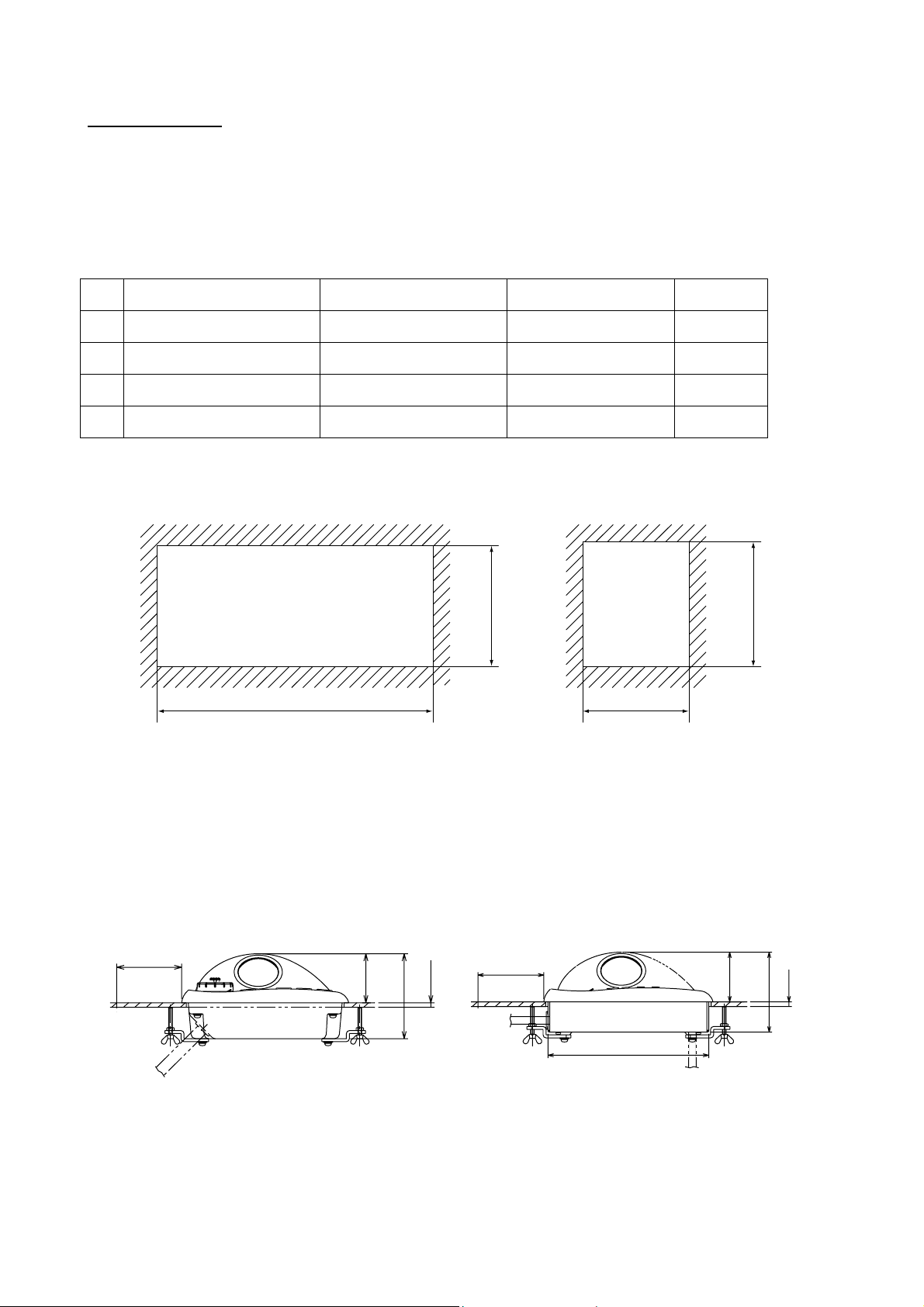
1.1 Antenna Unit
Mounting considerations
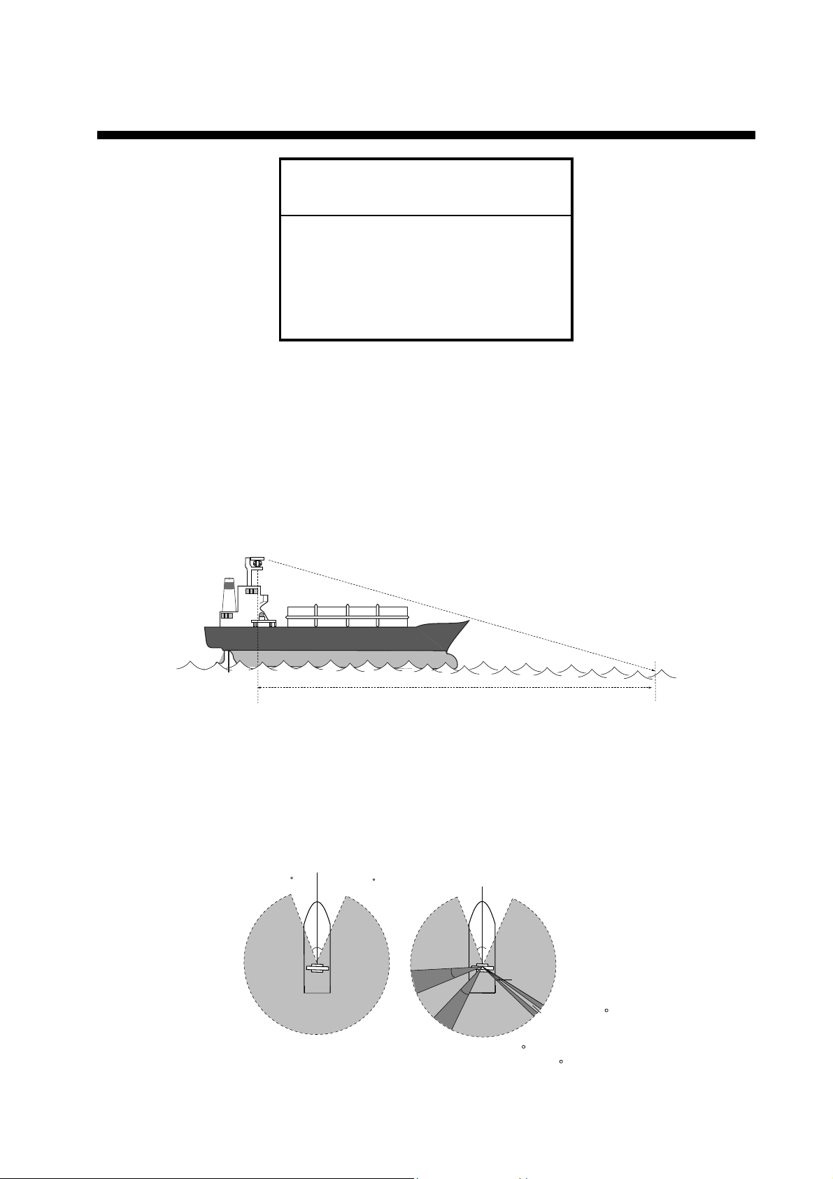
• The antenna unit is generally installed either on top of the wheelhouse, on the radar mast,
or on a suitable platform. Locate the antenna unit in an elevated position to permit
maximum target visibility.
• A line of sight from the antenna unit to the bow of the ship should hit the surface of the
sea in not more than 500 m or twice the ship’s length, depending which value is smaller,
for all load and trim conditions.
less than 500 m or twice the ship’s length
• Mount the antenna unit so that any blind sectors caused by objects (mast, etc.) are kept
to a minimum. No blind sector should exist in arc of the horizon from right ahead to 22.5°
aft of the beam to either side (see Figure 1 below). Also, individual blind sectors of more
than 5°, or the total arc of both blind sectors of more than 20°, should not occur in the
remaining arc (Figure 2). Note that any two blind sectors separated by 3° or less are
regarded as one sector.
bow
22.5
22.5
a
b
a, b, c: less than 5 respectively
a+b+c+... : less than 20
Figure 1
Figure 2
c
less than 3
1-1

1. MOUNTING
• Install the antenna unit away from interfering high-power energy sources and other
transmitting radio antenna.
• Keep the lower edge of the antenna unit above the safety rail by 500 mm or more.
• Two antenna units should be mounted as below:
more than 20
more
than 1 m
• No funnel, mast or derrick should be within the vertical beamwidth of the antenna unit in
the bow direction, especially zero degrees
on the radar picture.
±5°, to prevent blind sectors and false echoes
• It is rarely possible to place the antenna unit where a completely clear view in all
directions is available. Thus, you should determine the angular width and relative bearing
of any shadow sectors for their influence on the radar at the first opportunity after fitting.
• Locate a direction finder antenna clear of the antenna unit to prevent interference to the
direction finder. A separation of more than two meters is recommended.
• A magnetic compass will be affected if the antenna unit is placed too close to the
magnetic compass. Observe the compass safe distances on page ii to prevent deviation
of the magnetic compass.
• Do not paint the radiator aperture, to ensure proper emission of the radar waves.
• The antenna base is made of cast aluminum. To prevent electrolytic corrosion of the
antenna base, use the seal washers and corrosion-proof rubber mat and ground the unit
with the ground wire (supplied).
• Deposits and fumes from a funnel or other exhaust vent can adversely affect the aerial
performance and hot gases may distort the radiator portion. The antenna unit must not be
mounted where the temperature is more than 55°C.
• Leave sufficient space around the unit for maintenance and servicing. See the antenna
unit outline drawing for recommended maintenance space.
1-2
1. MOUNTING
Assembling the antenna unit
The antenna unit consists of the antenna radiator and the antenna unit chassis, and they
are packed separately. Fasten the antenna radiator to the antenna unit chassis as follows:
1. For the XN20AF, XN24AF, attach two guide pins to the underside of the antenna
radiator.
2. Remove the waveguide cap from the radiator bracket. The cap may be discarded.
3. Coat the waveguide flange with anticorrosive sealant as shown below.
10 mm
Hole for
a guide pin
5 mm
O-ring Waveguide cap
Anticorrosive sealant
Hole for
a guide pin
Coating the waveguide flange with anticorrosive sealant
4. Coat fixing holes for the antenna radiator with anticorrosive sealant.
5. Grease the O-ring and set it to the O-ring groove of the radiator flange.
6. Set the antenna radiator to the radiator bracket.
7. Coat hex bolts M8x40 (for XN-20AF or XN-24AF) or hex bolt M8x35/ flat washer/spring
washer (for XN-12AF) with anticorrosive sealant and use them to loosely fasten the
antenna radiator to the antenna unit chassis.
8. Remove two guide pins (inserted at step 1), and then tighten fixing bolts.
CAUTION
Be sure to remove the guide pins.
Injury may result if the guide pins loosen
and fall.
1-3
1. MOUNTING
Antenna radiator
Fastening the radiator to the radiator bracket
Guide pin
(XN20AF,
XN24AF
only)
O-ring
Waveguide
Radiator bracket
Hex bolt (M8x40), 8 pcs.
(XN20AF, XN24AF)
Hex. bolt (M8x35), 8 pcs.
Flat washer
Spring washer (XN12AF)
Fastening the antenna unit to the mounting platform
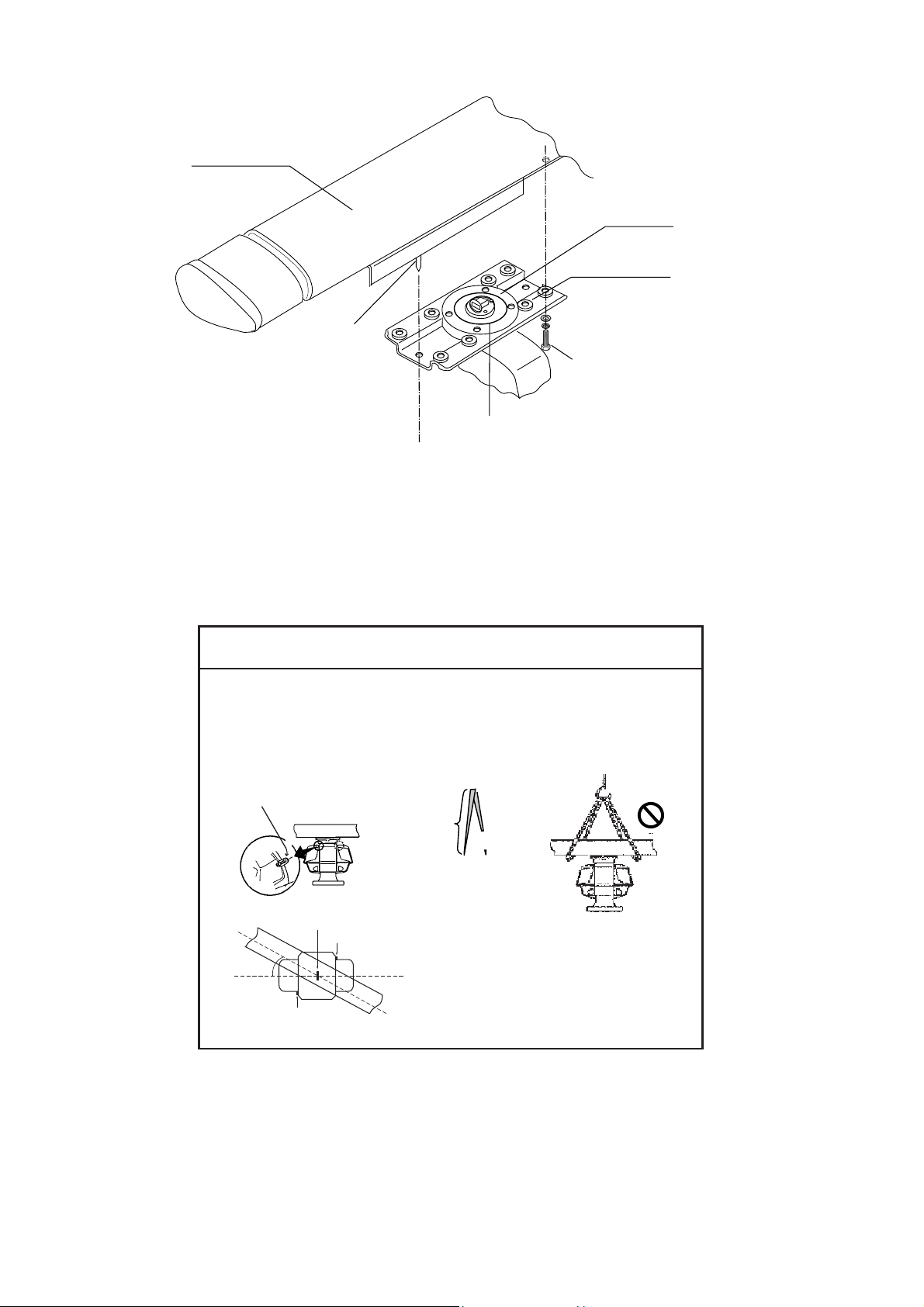
The antenna unit may be assembled before hoisting it to the mounting platform. However,
do not lift the antenna unit by the radiator. Always hold the unit by its housing. When using a
crane or hoist, lift the unit by the hoist rings which should be fastened to the bolt fixing
covers of the antenna housing.
NOTICE
- To hoist antenna unit aboard vessel, attach ropes to lifting fixtures and hoist unit with crane.
- To remove load from radiator when hoisting, the length of the rope between the radiator base
and the hook on the should be at least 130 cm.
- To keep the rope away from the radiator, turn the radiator and chassis approx. 30 degrees as
shown below.
- Be sure to remove the lfiting fixtures after hoisting is completed.
Lifting
fixture
130cm
Crane
Lifting fixture
Approx.
30 deg.
NO!
NO!
Lifting fixture
(Top view)
1. Construct a suitable mounting platform referring to the outline drawing at the end of this
manual.
2. Drill four mounting holes of 15 mm diameter and one cable entry hole of about 50 mm
diameter in the mounting platform.
3. Lay the rubber mat (supplied) on the mounting platform.
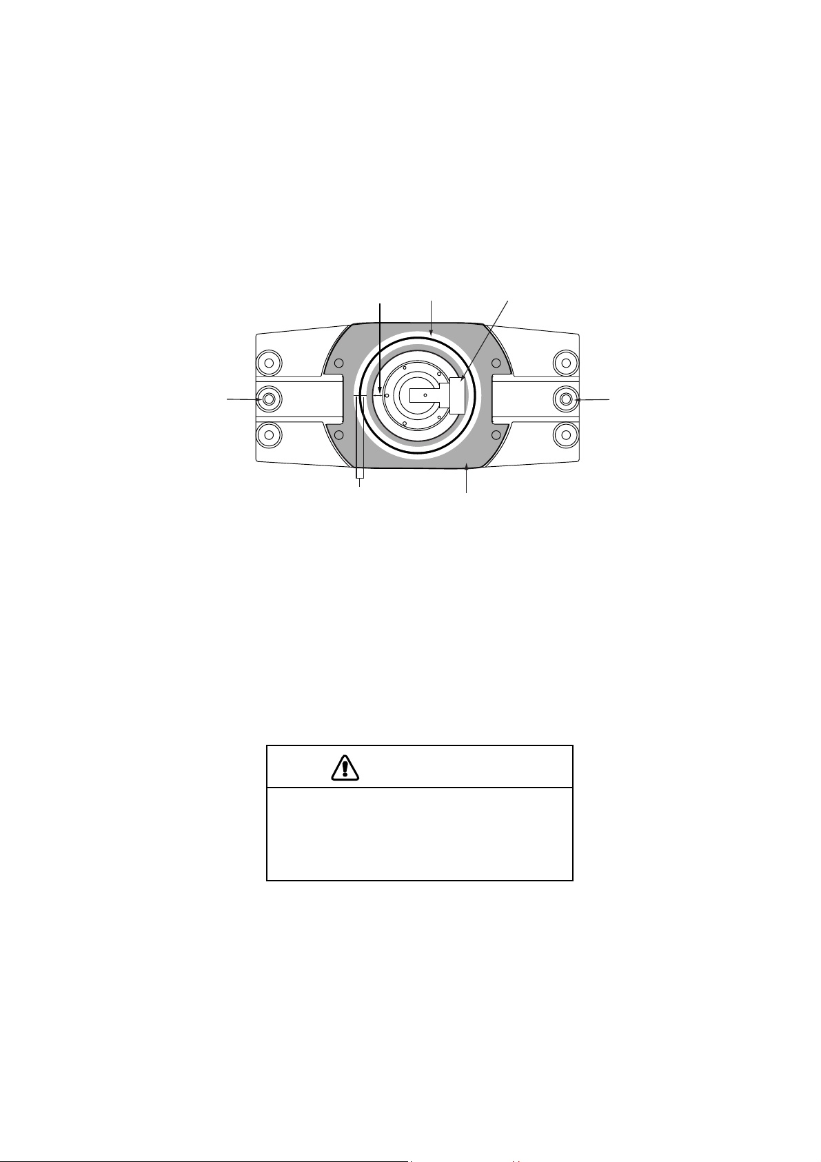
4. Place the antenna unit on the rubber mat, orienting the unit so the bow mark on its base
1-4
1. MOUNTING
4. Place the antenna unit on the rubber mat, orienting the unit so the bow mark on its base
is facing the ship’s bow.
Ground
terminal
Rubber
mat
Bow mark
Antenna unit, front view
5. Fasten the antenna unit to the mounting platform with M12x60 hex bolts, nuts, flat
washers and seal washers.
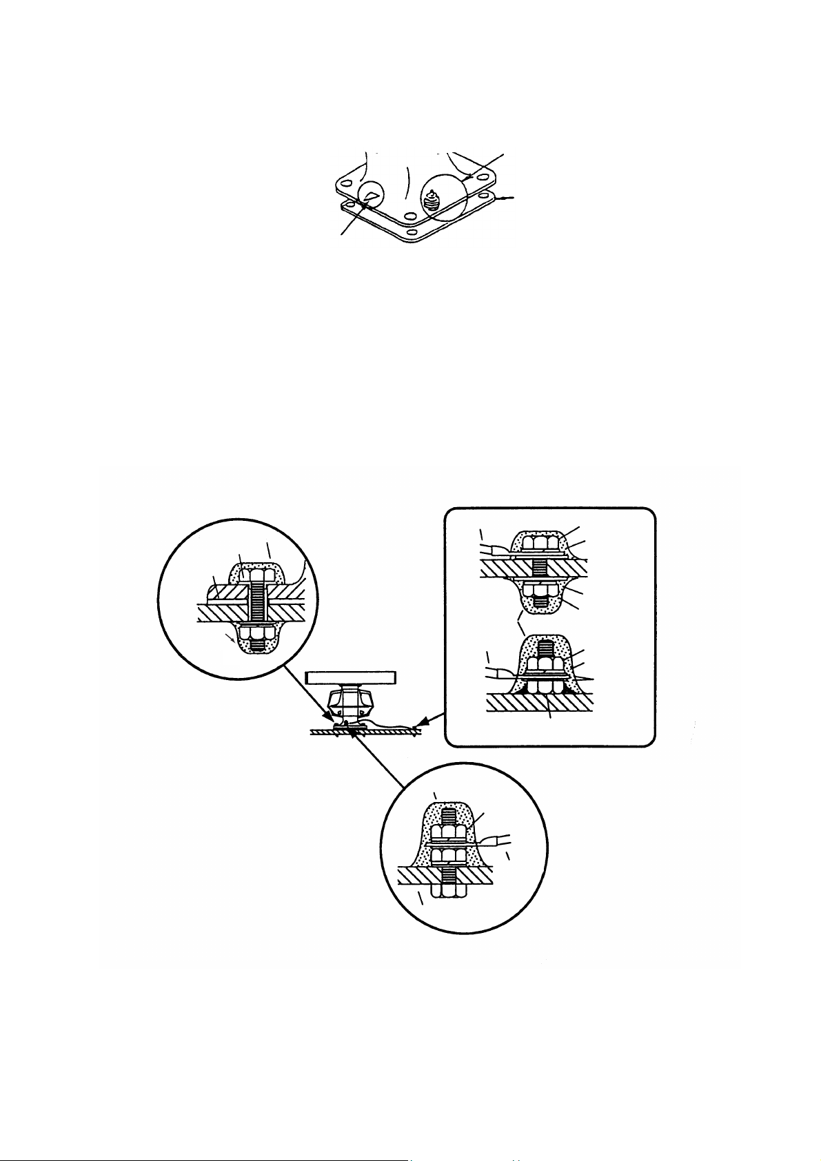
6. Using hex bolt (M6x25), nut (M6) and flat washer (M6), establish the ground system on
the mounting platform as shown below. The location should be within 340 mm of the
ground terminal on the antenna unit. Connect the ground wire (RW-4747, 340 mm,
supplied) between the grounding point and ground terminal on the antenna unit. Coat
the entire ground system with silicone sealant (supplied).
Anticorrosive sealant
Seal washer
Rubber mat
Anticorrosive
sealant
Ground wire
Anticorrosive
sealant
Ground wire
OR
Hex bolt
Spring washer
Spring washer
Hex nut
Hex nut
Spring washer
Flat washer
Hex bolt welded to
ship's superstructure
Anticorrosive sealant
Ground
terminal
Ground
wire
Antenna base
How to mount the antenna unit
1-5
1. MOUNTING
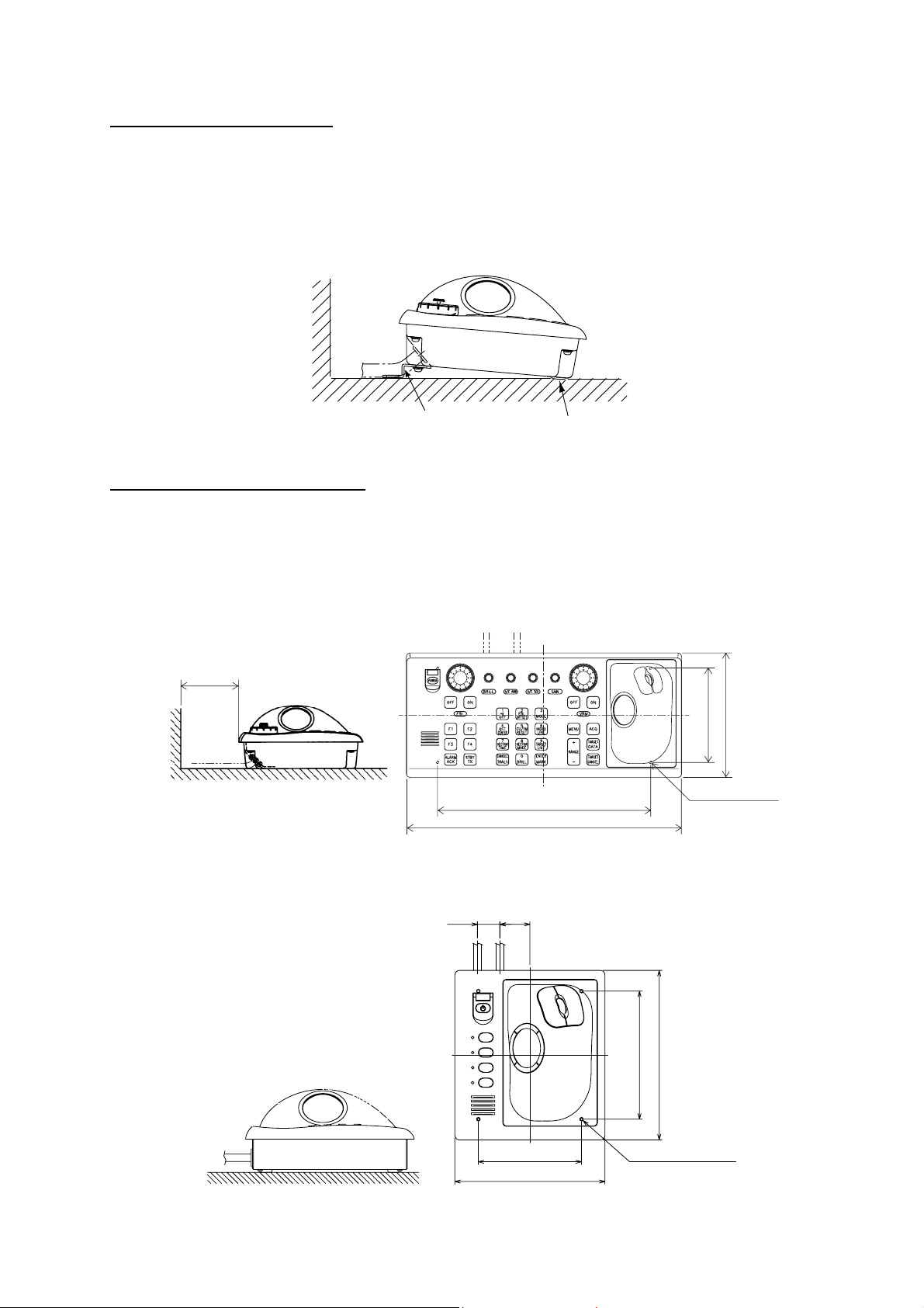
1.2 Monitor Unit
The monitor unit can be flush mounted in a console panel, or mounted on a desktop using
the optional accessories.
Note: FAR-2117-BB/2127-BB have no monitor unit. Prepare a suitable monitor locally.
Recommended monitor: SXGA (1280x1024), aspect ratio 5:4
Mounting considerations
When selecting a mounting location, keep in mind the following points:
• Select a location where the display unit can be viewed conveniently and where the
screen can be viewed while facing towards the bow.
• The optimal viewing distances for the radar display units are: MU-170C: 920 mm,
MU-201CR: 1080 mm, MU-231CR: 1200 mm. Select a suitable mounting location
considering the applicable distance.
• Locate the unit out of direct sunlight and away from heat sources because of heat that
can build up inside the cabinet.
• Locate the equipment away from places subject to water splash and rain.
• Leave sufficient space on the sides and rear of the unit to facilitate maintenance.
• A magnetic compass will be affected if the monitor unit is placed too close to the magnetic
compass. Observe the compass safe distances on page ii to prevent deviation of a
magnetic compass.
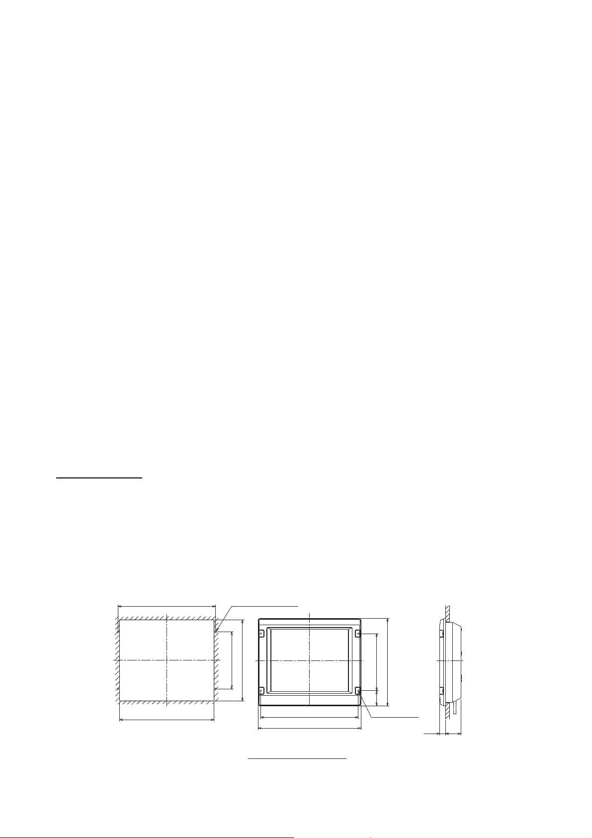
Mounting procedure
Flush mounting
Follow the procedure below to mount the monitor unit in a console panel.
1. Make cutout in mounting location referring to the outline drawing shown below.
2. Insert the monitor unit to the hole and fix it with four tapping screws (6x30).
3. Attach panel hooks near the fixing holes (upper part). See next page. These are used to
pull out the monitor unit from a console panel for servicing.
4. Attach four panel covers to the fixing holes.
506±1
4-FIXING HOLES
1-6
490
420
296±1
Monitor unit MU-201CR
(For FAR-2117/2127)
506
±1
534
454
296±1
(79)
4-φ8
FIXING HOLES
30
80
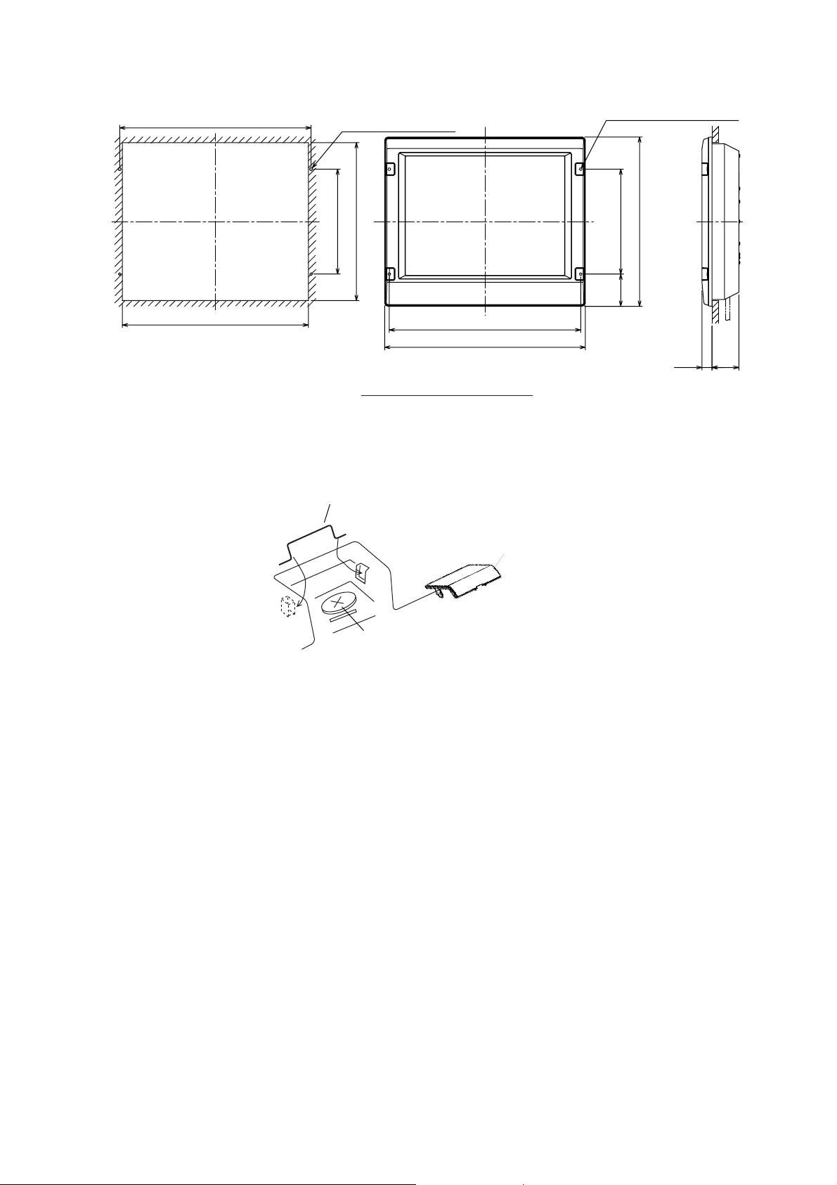
1. MOUNTING
570±1
554
4-FIXING HOLES
1
±
471
313
570
1
±
598
Monitor unit MU-231CR
(For FAR-2817/2827)
Flush mounting of monitor unit
Panel hook
4-φ8 FIXING HOLES
1
±
505
313
(96)
80
30
Panel cover
Fixing screw
Attaching panel hook and panel cover
Note: If you need to remove the monitor unit from the mounting panel, remove the four
panel covers with your fingernail and use two panel hooks supplied as accessories to
lift the monitor unit.
1-7

1. MOUNTING
Desktop mounting
Use the optional accessories to mount the monitor unit on a desktop.
• For FAR-2117/2127: FP03-09820 (Code No.: 008-535-560)
• For FAR-2817/2827: FP03-09830 (Code No.: 008-536-020)
Contents of FP03-09820/09830
Name Type Code No. Qty Remarks
Hanger L 03-163-1111 100-305-141 1
Hanger R 03-163-1112 100-305-181 1
03-163-1113 100-305-191 For FAR-2117/2127
Hanger stay
03-163-2071 100-305-371 1 For FAR-2817/2827
Hole plug CP-30-HP-13 000-160-074-10 2
Plastic rivet KB-13 Rivet Black 000-570-276-10 4
Hex. bolt M6x25 000-162-949-10 4
Hex. bolt M10x30 000-162-884-10 2
Spring washer M10 000-864-261 2
Flat washer M10 000-864-131 2
1. Assemble two hangers and hanger stay with two hex bolts (M10x30), flat washers and
spring washers and cover each hex bolt with hole plug.
2. Fix the above assembly to the mounting location with four hex bolts (M12, dockyard
supply).
3. Fasten the monitor unit to the mounting hanger assembly with four hex bolt (M6x25,
supplied).
4. Cover each hex bolts with panel cover.
5. Cover each holes for hand grip on the hangers with plastic rivets (4 pcs).
1-8
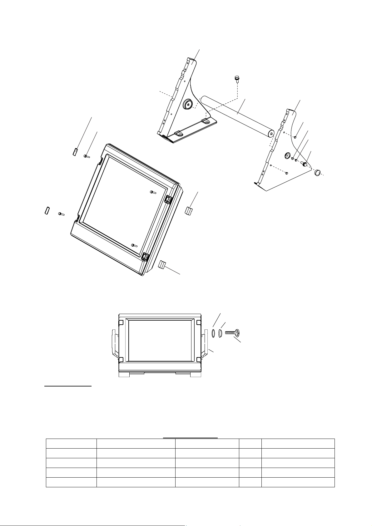
Hanger (L)
1. MOUNTING
M12 bolts for fixing
(Dockyard supply)
Hanger stay
Panel cover
Hex bolt
(M6x25)
Panel cover
To remove this, insert fingernail in groove.
Monitor Unit
The hand grip is optionally available for the desktop mounting monitor unit.
Wave washer
Hanger (R)
Plastic rivet
Flat Washer M10
Spring Washer M10
Hex bolt
M10x30
Hole plug
Rosette washer
Screw
Handle
Hood (option)
When it is too bright in the daytime, use the optional hood to shade the screen.
• For FAR-2117/2127: FP03-11500 (Code No.: 001-020-090)
• For FAR-2817/2827: FP03-11000 (Code No.: 008-571-680)
Contents of hood
Name Type Code No. Qty. Remarks
Hood (21) FP03-11501 001-020-120 1 For FAR-2117/2127
Hood (23) FP03-11001 008-571-700 1 For FAR-2817/2827
Fixing plate 03-163-2202-0 100-335-560-10 4
Screw M4x10 D=13 US304 000-862-543 4
1-9
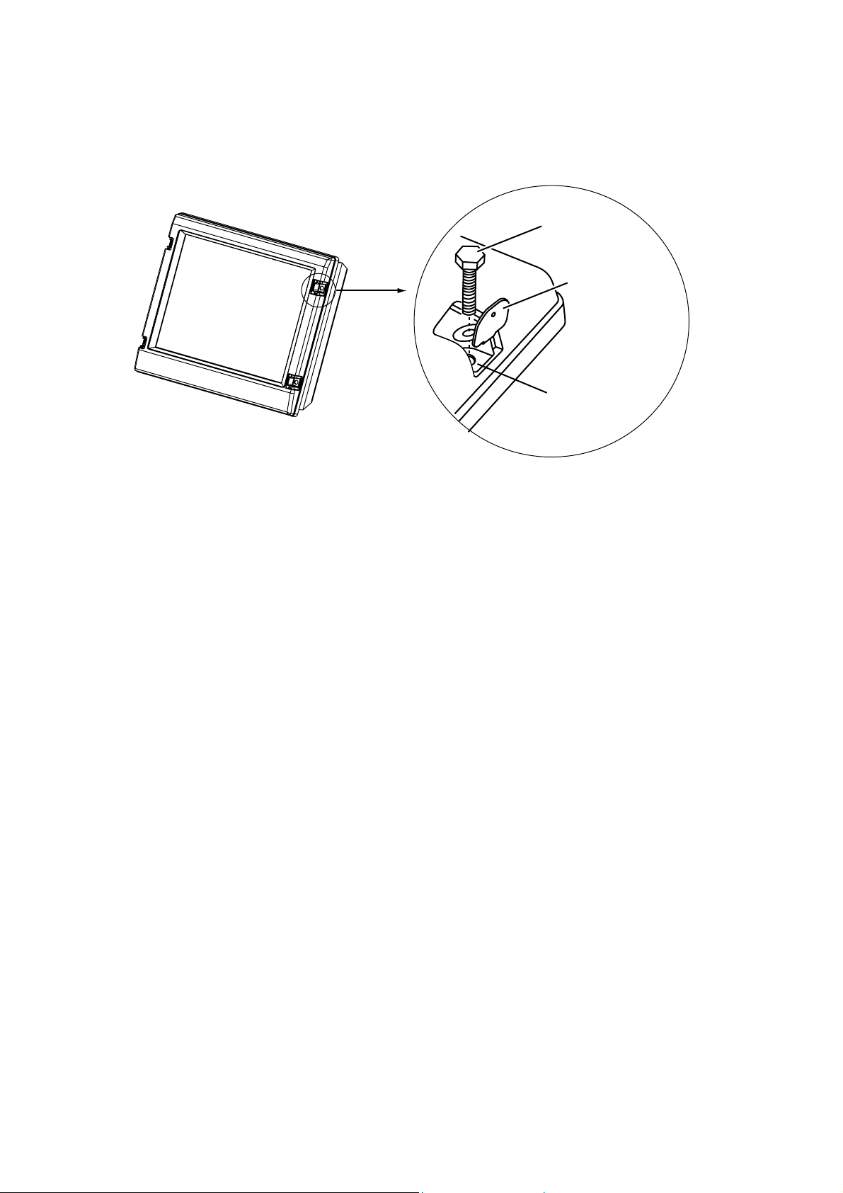
1. MOUNTING
1. Desktop mounting: Fasten the fixing plates to the fixing holes with the hex head bolts
(supplied).
Flush mounting: Fasten the display unit to the mounting location, and then attach the
fixing plates with four self-tapping screws.
Hex head bolt
Fixing plate
Fixing hole
2. Attach the hood to the display unit (the hood is outside of the fixing plates).
3. Fasten the hood to the fixing plates with four screws supplied (M4x10).
1.3 Control Unit
The control unit may be mounted on a desktop, with or without the KB fixing metal
(supplied), which mounts the control unit at an angle.
Mounting considerations
When selecting a mounting location, keep in mind the following points:
• Select a location where the control unit can be operated conveniently.
• Locate the unit away from heat sources because of heat that can build up inside the
cabinet.
• Locate the equipment away from places subject to water splash and rain.
• Determine the mounting location considering the length of the signal cable between the
control unit and the processor unit. (The 10m signal cable is attached to the control unit).
• A magnetic compass will be affected if the control unit is placed too close to the magnetic
compass. Observe the compass safe distances on page ii to prevent deviation of a
magnetic compass.
1-10
1. MOUNTING
Fixing with KB fixing plate
1. Fix the KB fixing plate to the bottom of the control unit.
2. Attach cushions (three for RCU-014, two for RCU-015/016) to the bottom of the control
unit as shown below.
3. Fix it to a desired location with self-tapping screws (local supply).
KB fixing plate
Cushion
Side view for RCU-014/015/016
Fixing without KB fixing metal
1. Drill four mounting holes of 5 mm diameter referring to the outline drawing at the back of
this manual.
2. Fix the control unit with four screws (M4) from under side of the desktop. (The M4
screws with a sufficient length for the thickness of the desktop should be provided
locally.)
#70
180
136±1
308±1
398
4-M4 (Fixing holes)
(bottom)
Control Unit RCU-014
24 32
F1
F2
F3
F4
110±1
160
180
136±1
4-M4 (Fixing holes)
(REAR)
RCU-015/016
1-11
1. MOUNTING
Flush mounting
Use the optional flush mount kit FP03-09870 to mount the control unit RCU-014, RCU-015
and/or RCU016 to a console panel.
Name: Flush mount kit
Type: FP03-09870
Code No.: 008-535-630
No. Name Type Code No. Qty
1 Mount plate 03-163-7531 100-306-261 4
2 Hex nut M5 000-863-108 4
3 Wing screw M5x40 000-162-682-10 4
4 Pan head screw M4x12 000-163-192-10 4
1. Prepare a cutout in the mounting location as shown in the figure below.
170±2 176±2
±2
388 150±2
For RCU-014 For RCU-015 and RCU-016
2. Set the control unit to the cutout.
3. Attach the mounting plate to the control unit with four screws from the rear side.
4. Screw the wing screw to each mounting plate and then insert hex bolt to each wing
screw.
5. Fasten each wing screw and then fasten the hex nuts as shown in the figure below.
#70
53
(P)
92
Note: P 10
#70
171
<
=
53
86
(P)
1-12
RCU-014 RCU-015/RCU-016
To connect RCU-016 in series with RCU-014
1. Pass the cable derived from RCU-016.
1. MOUNTING
2. Connect the connector
of the cable to J502.
3. Clamp the copper part of the cable with the cable clamp.
Inside of RCU-014
1-13
1. MOUNTING
To change the cable entry
To change the cable entry from the side (default) to the bottom, modify the unit as shown
below.
Screw
M3x8
3. Pass the cable from this hole.
4. In here, clamp the copper part
of the cable with the cable
clamp removed at step1.
Bottom of the unit
2. Pull out the cable.
Cable clamp
03-163-7804
Screw
M4x8
1. Remove the
cable clamp.
1-14
J524
J521
J522: If you connect RCU-016 in series with RCU-015, plug in here.
RCU-015/016: Changing cable entry
1. MOUNTING
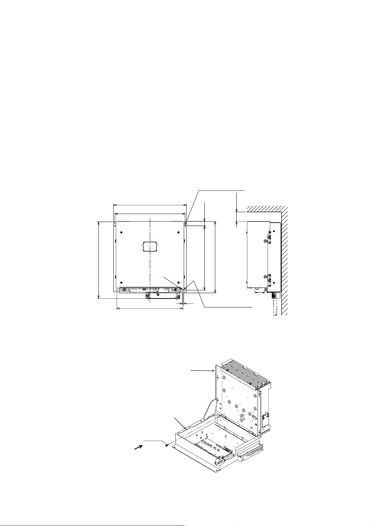
1.4 Processor Unit
Mounting considerations
When selecting a mounting location, keep in mind the following points:
• Locate the processor unit away from heat sources because of heat that can build up
inside the cabinet.
• Locate the equipment away from places subject to water splash and rain.
• Leave sufficient space at the sides and rear of the unit to facilitate maintenance.
• A magnetic compass will be affected if the processor unit is placed too close to the
magnetic compass. Observe the compass safe distances on page ii to prevent deviation
of a magnetic compass.
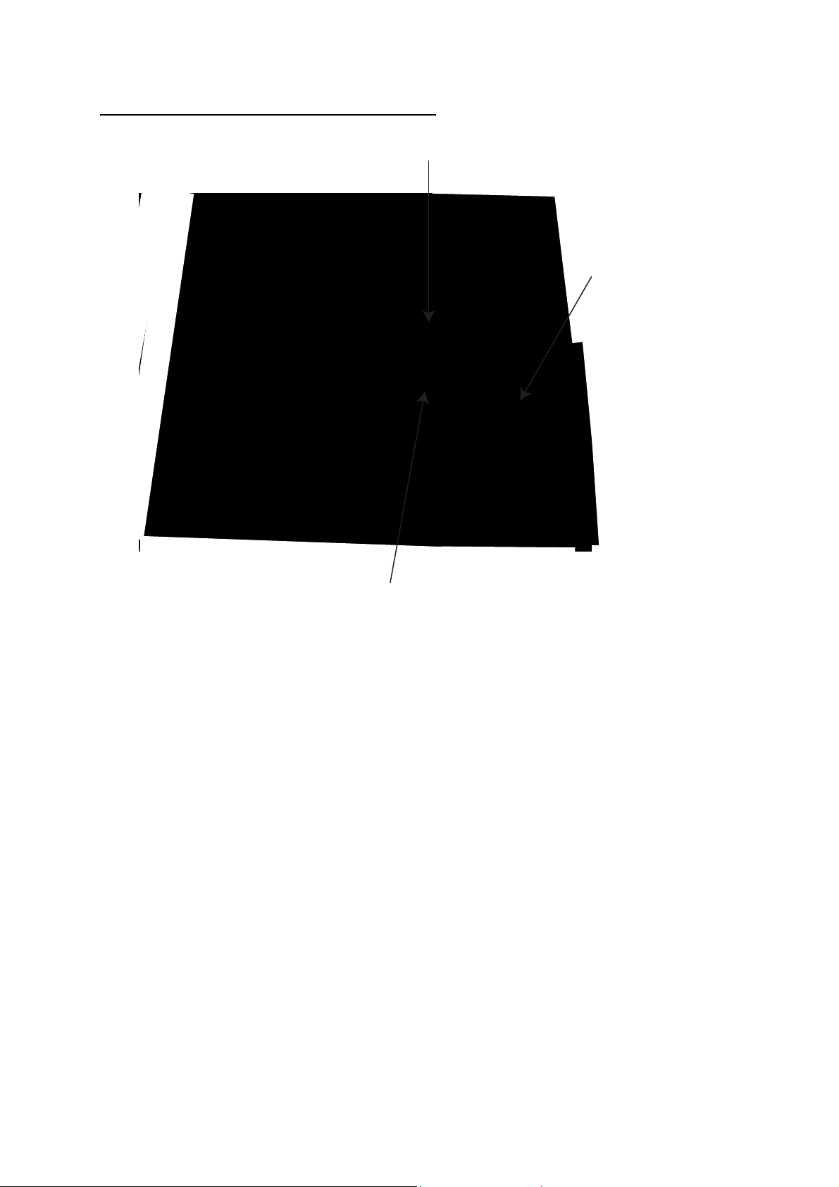
Mounting procedure
1. Fix the unit with four M6 bolts, or self-tapping screws.
2-φ7
FIXING HOLES
#50
410
385
370±1
350±1
R3.5
25
340±1
7
2-FIXING NOTCH
380
Floor mounting or bulkhead mounting
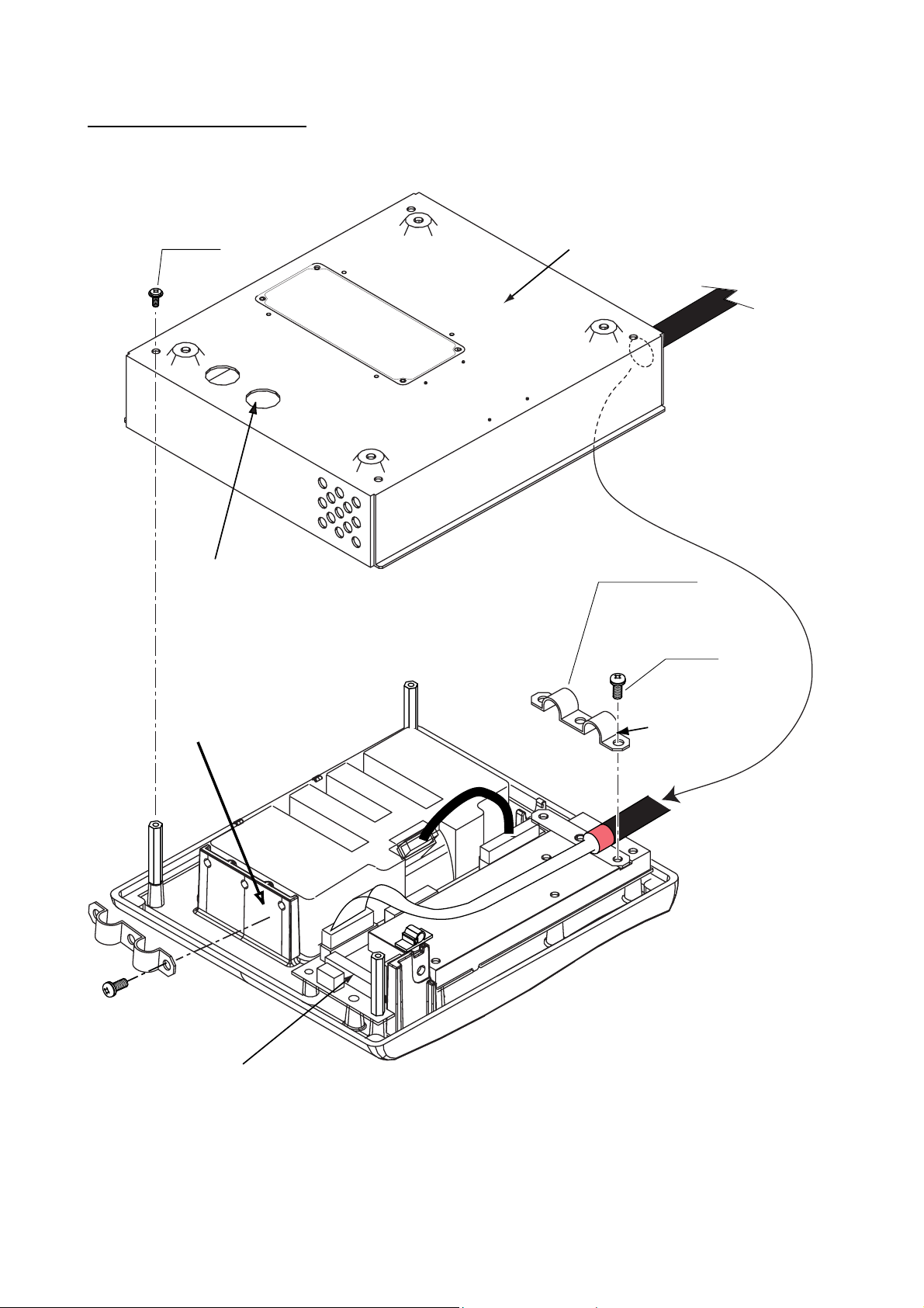
Note: If you fix the unit, cable entry upside, never remove the screw M3x10 that joints
the upper case assy. and lower case assy. of the processor unit.
Upper case assy.
Lower case assy.
Screw
M3x10
Never remove this screw.
Processor unit
1-15
 Loading...