

Furuno USA 9ZWRTR079, 9ZWRTR078 OPERATORS MANUAL

MARINE RADAR/ARPA
FAR-2117, FAR-2127
FAR-2817, FAR-2827
DRAFT
(August 21, 2003)

9-52 Ashihara-cho,9-52 Ashihara-cho,
x
A
A
*00014745200**00014745200*
*00014745200**00014745200*
*OME35190Z10**OME35190Z10*
Nishinomiya, JapanNishinomiya, Japan
Telephone :Telephone : 0798-65-21110798-65-2111
faxfa
ll rights reserved.
ll rights reserved.
PUB.No.PUB.No. OME-35190OME-35190
0798-65-42000798-65-4200
::
Printed in JapanPrinted in Japan
Your Local Agent/DealerYour Local Agent/Dealer
IRST EDITION :
IRST EDITION : . . 00000000
Z1Z1 ::AUG.AUG. 22,200322,2003
(( DAMIDAMI ))
FAR-2107/2807 SER.FAR-2107/2807 SER.
* 0 0 0 1 4 7 4 5 2 0 0 ** 0 0 0 1 4 7 4 5 2 0 0 *
*OME35190Z10**OME35190Z10*
* O M E 3 5 1 9 0 Z 1 0 ** O M E 3 5 1 9 0 Z 1 0 *
SAFETY INSTRUCTIONS
WARNING
WARNING
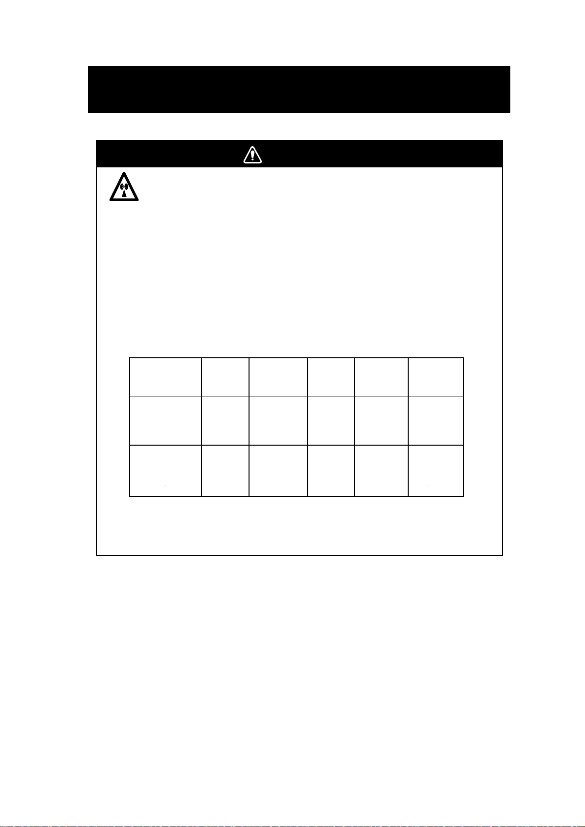
Radio Frequency Radiation Hazard
The radar antenna emits electromagnetic radio frequency (RF) energy which can be
harmful, particularly to your eyes. Never look directly into the antenna aperture from a
close distance while the radar is in operation or expose yourself to the transmitting
antenna at a close distance.
Distances at which RF radiation levels of 100 and 10 W/m
below.
Note: If the antenna unit is installed at a close distance in front of the wheel house,
your administration may require halt of transmission within a certain sector of antenna
revolution. This is possible. Ask your FURUNO representative or dealer to provide
this feature.
Model TR unit Magnetron Antenna
FAR-2827/2127 RTR-079 MG5436 XN12AF 0.80 m 11.20 m
FAR-2827/2127 RTR-079 MG5436 XN20AF 0.40 m 8.60 m
FAR-2827/2127 RTR-079 MG5436 XN24AF 0.20 m 5.80 m
FAR-2817/2117 RTR-078 MG4010
FAR-2817/2117 RTR-078 MG4010
FAR-2817/2117 RTR-078 MG4010
1 XN12AF: 4 ft
XN20AF: 6.5 ft
XN24AF: 8 ft
2 Or MAF1425B
2
XN12AF 0.30 m 4.20 m
2
XN20AF 0.10 m 3.00 m
2
XN24AF -- 2.40 m
2
exist are given in the table
Distance to
1
100 W/m
point
Distance to
2
10 W/m
point
2
i
SAFETY INSTRUCTIONS
WARNING
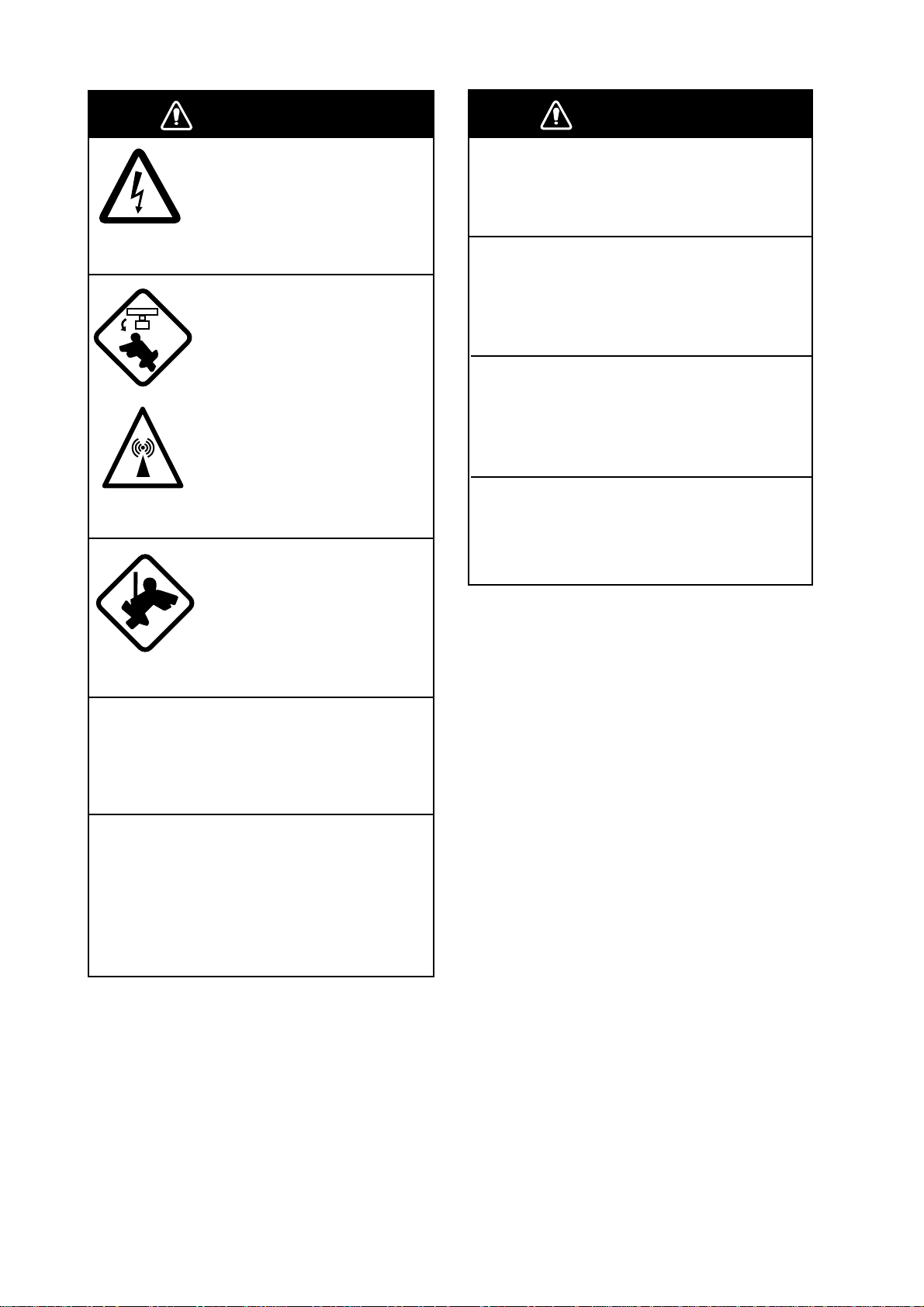
ELECTRICAL SHOCK HAZARD
Do not open the equipment.
Only qualified personnel
should work inside the
equipment.
Turn off the radar power
switch before servicing the
antenna unit. Post a warning sign near the switch
indicating it should not be
turned on while the antenna
unit is being serviced.
Prevent the potential risk of
being struck by the rotating
antenna and exposure to
RF radiation hazard.
Wear a safety belt and hard
hat when working on the
antenna unit.
WARNING
Use the proper fuse.
Use of a wrong fuse can result in damage
to the equipment or cause fire.
Keep heater away from equipment.
Heat can alter equipment shape and melt
the power cord, which can cause fire or
electrical shock.
Do not place liquid-filled containers
near the equipment.
Fire or electrical shock can result if a liquid
spills into the equipment.
Do not operate the equipment with wet
hands.
Electrical shock can result.
Serious injury or death can
result if someone falls from
the radar antenna mast.
Do not disassemble or modify the
equipment.
Fire, electrical shock or serious injury can
result.
Immediately turn off the power at the
ship's mains switchboard if water
leaks into the equipment or the equipment is emitting smoke or fire.
Continued use can cause fatal damage to
the equipment.
ii

SAFETY INSTRUCTIONS
WARNING
CAUTION
WARNING
No one navigational aid should be relied
upon for the safety of vessel and crew.
The navigator has the responsibility to
check all aids available to confirm
position. Electronic aids are not
a substitute for basic navigational
principles and common sense.
• This ARPA automatically tracks
automatically or manually acquired radar
targets and calculates their courses and
speeds, indicating them by vectors. Since
the data generated by the auto plotter
are based on what radar targets are
selected, the radar must always be
optimally tuned for use with the auto
plotter, to ensure required targets will not
be lost or unwanted targets such as sea
returns and noise will not be acquired
and tracked.
• A target does not always mean a land mass, reef, ships or other surface vessels
but can imply returns from sea surface
and clutter. As the level of clutter changes
with environment, the operator should
properly adjust the A/C SEA, A/C RAIN
and GAIN controls to be sure target
echoes are not eliminated from the
radar screen.
CAUTION
The plotting accuracy and response of
this ARPA meets IMO standards.
Tracking accuracy is affected by the
following:
• Tracking accuracy is affected by course
change. One to two minutes is required to
restore vectors to full accuracy after an
abrupt course change. (The actual
amount depends on gyrocompass
specifications.)
• The amount of tracking delay is inversely
proportional to the relative speed of the
target. Delay is on the order of 15—30
seconds for high relative speed; 30—60
seconds for low relative speed.
The data generated by ARPA, AIS and
video plotter are intended for
reference only.
Refer to official nautical charts for
detailed and up-to-date information.
Replace the battery in the memory card
within 10 minutes.
Loss of data may result if the above time
is exceeded.
The battery in memory cards must be
inserted plus (+) side up.
Inserting the battery minus(-) side up may
cause the battery to explode.
iii
SAFETY INSTRUCTIONS
v
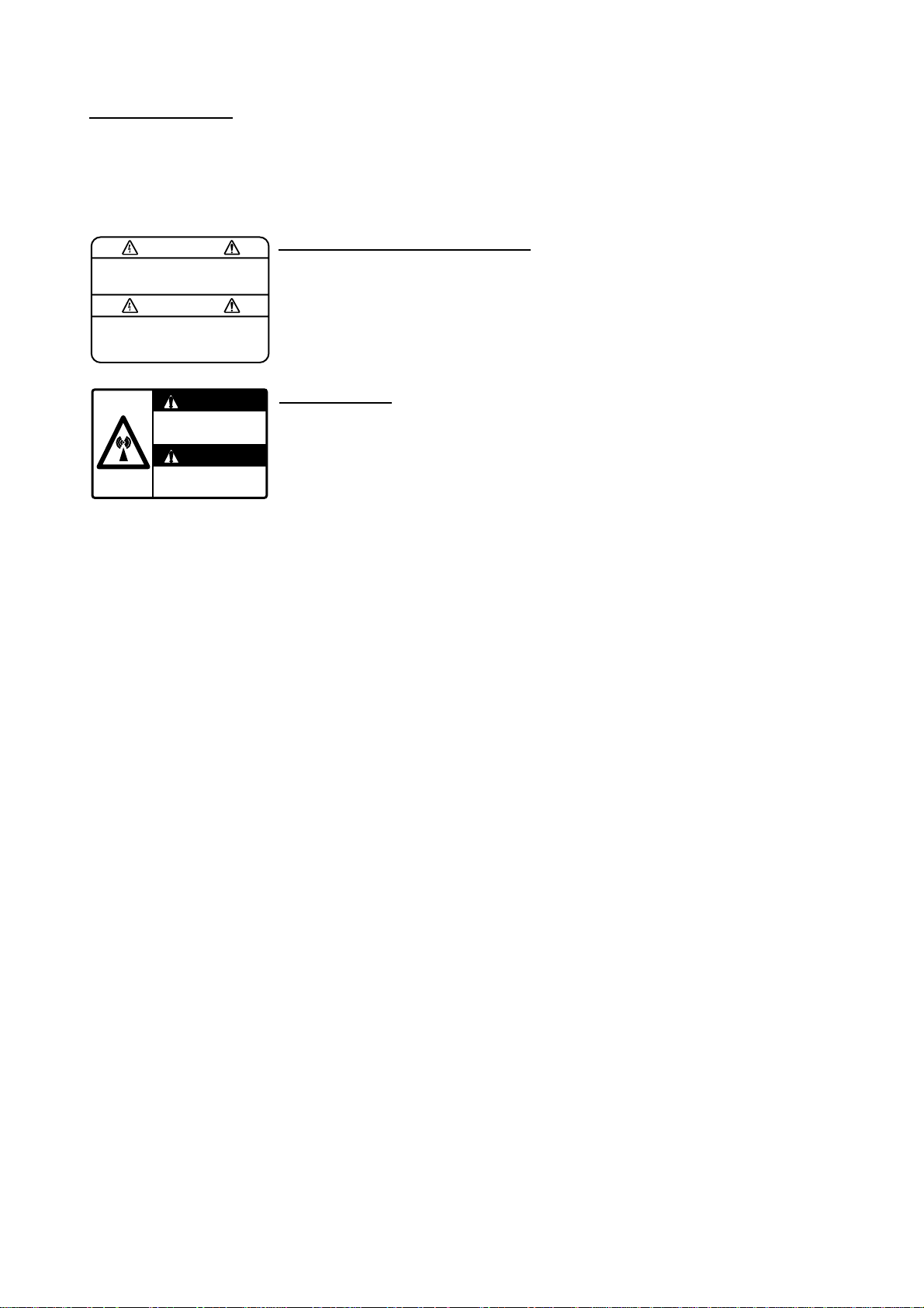
WARNING LABEL
Warning labels are attached to the
equipment. Do not remove any label.
If a label is missing or damaged,
contact a FURUNO agent or dealer
about replacement.
WARNING
To avoid electrical shock, do not
remove cover. No user-serviceable
parts inside.
WARNING
Radiation hazard. Only qualified
personnel should work inside scanner.
Confirm that TX has stopped before
opening scanner.
DISPLAY UNIT, PROCESSOR UNIT
Name: Warning Label (1)
Type: 86-003-1011-0
Code No.: 100-236-230
ANTENNA UNIT
Name: Radiation Warning Label
Type: 03-142-3201-0
Code No.: 100-266-890
i

v
TABLE OF CONTENTS
FOREWORD ........................................................................................................ ix
PROGRAM NUMBER .......................................................................................... xi
SYSTEM CONFIGURATION............................................................................... xii
SPECIFICATIONS.............................................................................................. xiii
1. RADAR OPERATION ....................................................................................1-1
1.1 Turning on the Power................................................................................................. 1-1
1.2 Transmitter ON ..........................................................................................................1-1
1.3 Control Unit................................................................................................................ 1-3
1.4 Main Menu................................................................................................................. 1-5
1.5 Operation Using the On-Screen Boxes...................................................................... 1-7
1.6 Cursor Menu............................................................................................................ 1-10
1.7 Monitor Brilliance..................................................................................................... 1-11
1.8 Choosing the Display Mode .....................................................................................1-12
1.9 On-Screen Boxes and Markers................................................................................ 1-13
1.10 Tuning the Receiver................................................................................................. 1-15
1.10.1 Choosing the tuning method..........................................................................1-15
1.10.2 Initializing tuning............................................................................................1-15
1.10.3 Automatic tuning............................................................................................1-16
1.10.4 Manual tuning................................................................................................1-16
1.11 Aligning Gyrocompass............................................................................................. 1-17
1.12 Presentation Modes................................................................................................. 1-18
1.12.1 Choosing presentation mode......................................................................... 1-18
1.12.2 Description of presentation modes ................................................................ 1-19
1.13 Entering Own Ship's Speed ..................................................................................... 1-22
1.13.1 Automatic speed input by log or GPS navigator ............................................1-22
1.13.2 Manual speed input....................................................................................... 1-23
1.14 Choosing the Range Scale ...................................................................................... 1-24
1.15 Choosing the Pulselength........................................................................................ 1-25
1.15.1 Choosing pulselength.................................................................................... 1-25
1.15.2 Choosing pulselength.................................................................................... 1-26
1.16 Adjusting the Sensitivity........................................................................................... 1-27
1.17 Suppressing Sea Clutter.......................................................................................... 1-28
1.17.1 Choosing method of adjustment.................................................................... 1-28
1.17.2 Automatic adjustment by the A/C SEA control ............................................... 1-28
1.17.3 Manual adjustment of A/C SEA ..................................................................... 1-29
1.18 Suppressing Rain Clutter ......................................................................................... 1-30
1.18.1 Choosing method of adjustment.................................................................... 1-30
1.18.2 Automatic adjustment of A/C RAIN................................................................ 1-31
1.18.3 Manual adjustment of A/C RAIN.................................................................... 1-31
1.19 Interference Rejector ...............................................................................................1-32
1.20 Measuring the Range...............................................................................................1-34
1.20.1 Turning range rings on/off.............................................................................. 1-34
1.20.2 Measuring range by the variable range marker (VRM) .................................. 1-35

TABLE OF CONTENTS
1.21 Measuring the Bearing ............................................................................................ 1-37
1.21.1 Measuring the bearing .................................................................................. 1-37
1.21.2 Choosing true or relative bearing .................................................................. 1-39
1.22 Collision Assessment by Offset EBL........................................................................ 1-40
1.22.1 How to assess risk of collision by the offset EBL........................................... 1-40
1.22.2 Choosing point of reference for origin point of offset EBL.............................. 1-41
1.23 Measuring Range and Bearing Between Two Targets ............................................. 1-42
1.24 Setting a Guard Zone .............................................................................................. 1-43
1.24.1 How to set a guard zone............................................................................... 1-43
1.24.2 Acknowledging the alarm.............................................................................. 1-44
1.24.3 Deactivating a guard zone ............................................................................ 1-44
1.24.4 Guard alarm attributes .................................................................................. 1-45
1.25 Off-Centering the Display ........................................................................................ 1-46
1.26 Echo Stretch............................................................................................................ 1-47
1.27 Echo Averaging ....................................................................................................... 1-48
1.28 Target Trails............................................................................................................. 1-49
1.28.1 True or relative trails ..................................................................................... 1-49
1.28.2 Trail time....................................................................................................... 1-50
1.28.3 Trail gradation............................................................................................... 1-50
1.28.4 Resetting target trails .................................................................................... 1-51
1.28.5 Trail copy ...................................................................................................... 1-51
1.28.6 Trail level ...................................................................................................... 1-52
1.28.7 Canceling trails ............................................................................................. 1-52
1.29 Parallel Index Lines................................................................................................. 1-53
1.29.1 Displaying, erasing parallel index lines.......................................................... 1-53
1.29.2 Adjusting index line orientation, index line interval ........................................ 1-54
1.29.3 Index line bearing reference.......................................................................... 1-54
1.29.4 Choosing maximum number of index lines to display.................................... 1-55
1.29.5 Index line mode ............................................................................................ 1-55
1.30 Origin Mark.............................................................................................................. 1-56
1.30.1 Entering origin marks.................................................................................... 1-56
1.30.2 Origin mark stabilization................................................................................ 1-58
1.30.3 Deleting individual origin marks..................................................................... 1-58
1.31 Zoom....................................................................................................................... 1-59
1.32 Markers................................................................................................................... 1-60
1.32.1 Heading marker and heading line ................................................................. 1-60
1.32.2 Stern marker................................................................................................. 1-60
1.32.3 North marker................................................................................................. 1-60
1.32.4 Own ship symbol .......................................................................................... 1-61
1.33 Automatic Picture Setup According to Navigation Purpose...................................... 1-62
1.33.1 Choosing a picture setup option.................................................................... 1-63
1.33.2 Restoring default picture setup options......................................................... 1-64
1.33.3 User-programmable picture setups............................................................... 1-65
1.34 Programming Function Keys ................................................................................... 1-67
1.34.1 Activating a function key ............................................................................... 1-67
1.34.2 Programming the functions keys................................................................... 1-67
1.35 Ship’s Position......................................................................................................... 1-71
1.36 Noise Rejector......................................................................................................... 1-72
vi

TABLE OF CONTENTS
v
1.37 Suppressing Second-trace Echoes.......................................................................... 1-73
1.38 Adjusting Brilliance of Screen Data.......................................................................... 1-74
1.39 Watch Alarm ............................................................................................................1-75
1.40 Setting Up Nav Data................................................................................................ 1-76
1.41 Text Window Setup ..................................................................................................1-78
1.42 Customizing Operation ............................................................................................ 1-80
1.43 Alarms .....................................................................................................................1-82
1.43.1 Alarm description...........................................................................................1-82
1.43.2 Outputting alarm signal..................................................................................1-84
1.44 Choosing the Antenna, Displaying Antenna Information........................................... 1-85
1.44.1 Choosing the antenna ................................................................................... 1-85
1.44.2 Displaying antenna information ..................................................................... 1-85
1.45 Cursor Data ............................................................................................................. 1-86
1.46 Performance Monitor ............................................................................................... 1-87
1.46.1 Activating, deactivating the performance monitor ..........................................1-87
1.46.2 Checking radar performance ......................................................................... 1-87
1.47 Wiper....................................................................................................................... 1-89
1.48 Own Ship Marker..................................................................................................... 1-90
1.49 Color and Brilliance Sets.......................................................................................... 1-91
1.49.1 Choosing color and brilliance set................................................................... 1-91
1.49.2 Presetting color and brilliance set..................................................................1-91
2. RADAR OBSERVATION ............................................................................... 2-1
2.1 General......................................................................................................................2-1
2.1.1 Minimum and maximum ranges.......................................................................2-1
2.2 False Echoes............................................................................................................. 2-3
2.3 SART (Search and Rescue Transponder).................................................................. 2-5
2.3.1 SART description ............................................................................................ 2-5
2.3.2 Showing SART marks on the radar display ..................................................... 2-6
2.3.3 General remarks on receiving SART ...............................................................2-7
2.4 RACON......................................................................................................................2-8
3. ARPA OPERATION ....................................................................................... 3-1
3.1 Usage Precautions .................................................................................................... 3-1
3.2 Controls for ARPA...................................................................................................... 3-2
3.3 Activating, Deactivating ARPA ...................................................................................3-3
3.4 Entering Own Ship's Speed ....................................................................................... 3-3
3.4.1 Echo-referenced speed input...........................................................................3-3
3.5 Automatic Acquisition................................................................................................. 3-5
3.5.1 Enabling auto acquisition.................................................................................3-5
3.5.2 Terminating tracking of targets (including reference targets)............................ 3-6
3.6 Manual Acquisition..................................................................................................... 3-7
3.6.1 Setting manual acquisition conditions.............................................................. 3-7
3.6.2 Manually acquiring a target..............................................................................3-7
3.7 ARPA Symbols and ARPA Symbol Attributes ............................................................. 3-9
3.7.1 ARPA symbols.................................................................................................3-9
3.7.2 ARPA symbol brilliance.................................................................................. 3-10
3.7.3 ARPA symbol color and size.......................................................................... 3-11

TABLE OF CONTENTS
3.8 Displaying Target Data ............................................................................................ 3-12
3.8.1 Displaying individual target data.................................................................... 3-12
3.8.2 Target list ...................................................................................................... 3-14
3.9 Vector Modes .......................................................................................................... 3-16
3.9.1 Description of vectors ................................................................................... 3-16
3.9.2 Vector motion and length .............................................................................. 3-17
3.10 Past Position Display............................................................................................... 3-18
3.10.1 Displaying and erasing past position points, choosing past position
plot interval ................................................................................................... 3-18
3.10.2 Past position display attributes...................................................................... 3-19
3.11 Set and Drift ............................................................................................................ 3-20
3.12 Setting CPA/TCPA Alarm Ranges............................................................................ 3-21
3.12.1 Setting CPA/TCPA alarm ranges................................................................... 3-21
3.12.2 Acknowledging CPA/TCPA alarm.................................................................. 3-22
3.13 Setting a Guard Zone .............................................................................................. 3-23
3.13.1 Activating the guard zone.............................................................................. 3-23
3.13.2 Sleeping, deactivating a guard zone ............................................................. 3-24
3.13.3 Acknowledging the guard zone alarm ........................................................... 3-24
3.13.4 Guard zone reference................................................................................... 3-25
3.13.5 Guard zone shape and stabilization.............................................................. 3-25
3.14 Operational Warnings.............................................................................................. 3-26
3.15 Trial Maneuver ........................................................................................................ 3-28
3.15.1 Types of trial maneuvers............................................................................... 3-28
3.15.2 Performing a trial maneuver.......................................................................... 3-29
3.15.3 Terminating a trial maneuver......................................................................... 3-31
3.16 ARPA Performance Test .......................................................................................... 3-32
3.17 Criteria for Selecting Targets for Tracking................................................................ 3-34
3.18 Factors Affecting ARPA Functions ........................................................................... 3-36
4. AIS OPERATION........................................................................................... 4-1
4.1 Controls for AIS......................................................................................................... 4-1
4.2 Enabling/Disabling the AIS ........................................................................................ 4-2
4.3 Turning AIS Display On/Off........................................................................................ 4-3
4.4 Activating Targets...................................................................................................... 4-4
4.4.1 Activating specific target ................................................................................. 4-4
4.4.2 Activating all targets........................................................................................ 4-4
4.5 Sleeping Targets........................................................................................................ 4-5
4.5.1 Sleeping an AIS target .................................................................................... 4-5
4.5.2 Sleeping all AIS targets................................................................................... 4-5
4.6 Displaying Target Data .............................................................................................. 4-6
4.6.1 Basic data....................................................................................................... 4-6
4.6.2 Detailed target data......................................................................................... 4-7
4.7 AIS Symbol Attributes................................................................................................ 4-8
4.7.1 AIS symbol brilliance....................................................................................... 4-8
4.7.2 AIS symbol size and color............................................................................... 4-9
vi

TABLE OF CONTENTS
4.8 Past Position Display............................................................................................... 4-10
4.8.1 Displaying and erasing past position points, choosing past position
plot interval....................................................................................................4-10
4.8.2 Past position display attributes...................................................................... 4-11
4.9 Lost Target............................................................................................................... 4-12
4.10 ROT Setting............................................................................................................. 4-13
4.11 Consolidating (fusing) ARPA and AIS Targets .......................................................... 4-14
4.12 AIS System Messages............................................................................................. 4-15
4.13 Viewing AIS Messages ............................................................................................ 4-16
4.13.1 Manually viewing received AIS messages..................................................... 4-16
4.13.2 Automatically displaying AIS messages......................................................... 4-17
5. VIDEO PLOTTER OPERATION ....................................................................5-1
5.1 General......................................................................................................................5-1
5.2 Display Modes ...........................................................................................................5-1
5.3 Presentation Modes................................................................................................... 5-2
5.4 Radar Map................................................................................................................. 5-3
5.4.1 Turning on the radar map display ....................................................................5-3
5.4.2 Inscribing radar map marks and lines.............................................................. 5-4
5.4.3 Choosing mark color ....................................................................................... 5-5
5.5 Erasing Radar Map Marks and Lines......................................................................... 5-6
5.5.1 Erasing individual radar map marks and lines .................................................5-6
5.5.2 Erasing all radar map marks and lines.............................................................5-7
5.6 Radar Map Corrections..............................................................................................5-8
5.6.1 Radar map correction...................................................................................... 5-8
5.6.2 Cursor data correction..................................................................................... 5-8
5.7 Chart Cards............................................................................................................... 5-9
5.7.1 Displaying a chart............................................................................................ 5-9
5.7.2 Chart position correction................................................................................5-10
5.7.3 Correcting cursor data................................................................................... 5-10
5.7.4 Chart land color............................................................................................. 5-11
5.8 Hiding/Showing Graphics on the Video Plotter Display ............................................5-12
5.9 Track........................................................................................................................ 5-13
5.9.1 Plotting own ship’s track................................................................................ 5-13
5.9.2 Plotting other ships’ track...............................................................................5-14
5.9.3 Choosing track color......................................................................................5-14
5.9.4 Erasing track ................................................................................................. 5-15
5.10 Marks and Lines ...................................................................................................... 5-16
5.10.1 Inscribing marks and lines............................................................................. 5-16
5.10.2 Choosing mark color ..................................................................................... 5-17
5.11 Erasing Marks and Lines .........................................................................................5-18
5.11.1 Erasing individual marks/lines .......................................................................5-18
5.11.2 Erasing all marks and lines............................................................................ 5-19
5.12 Waypoints................................................................................................................5-20
5.12.1 Entering waypoints ........................................................................................ 5-20
5.12.2 Editing, erasing waypoints from the menu .....................................................5-23
5.12.3 Erasing waypoints......................................................................................... 5-24
vii

TABLE OF CONTENTS
5.12.4 Waypoint list ................................................................................................. 5-25
5.12.5 Displaying waypoint name and number......................................................... 5-26
5.13 Nav Lines................................................................................................................ 5-27
5.13.1 Entering new nav line.................................................................................... 5-27
5.13.2 Editing nav lines............................................................................................ 5-28
5.13.3 Nav line list ................................................................................................... 5-29
5.13.4 Erasing nav lines .......................................................................................... 5-30
5.13.5 Setting up nav lines....................................................................................... 5-31
5.13.6 Displaying nav line, waypoint mark............................................................... 5-33
5.14 Recording Data ....................................................................................................... 5-35
5.14.1 Initializing memory (RAM) cards ................................................................... 5-35
5.14.2 Recording data ............................................................................................. 5-36
5.15 Replaying Data........................................................................................................ 5-38
5.16 Deleting Files .......................................................................................................... 5-39
6. MAINTENANCE, TROUBLESHOOTING...................................................... 6-1
6.1 Periodic Maintenance Schedule ................................................................................ 6-2
6.2 Life Expectancy of Major Parts.................................................................................. 6-3
6.3 Replacing the Fuse ................................................................................................... 6-3
6.4 Replacement of Batteries.......................................................................................... 6-4
6.4.1 Battery on GC board....................................................................................... 6-4
6.4.2 Battery in memory cards................................................................................. 6-4
6.5 Easy Troubleshooting................................................................................................ 6-5
6.6 Advanced-level Troubleshooting................................................................................ 6-6
6.7 Diagnostics................................................................................................................ 6-9
APPENDIX ......................................................................................................AP-1
1. Menu Tree...................................................................................................................AP-1
2. Digital Interface............................................................................................................AP-8
3. Longitude Error Table (on 96 nm range scale)...........................................................AP-27
INDEX............................................................................................................... IN-1
viii

FOREWORD
A Word to the Owner of the FAR-28x7/FAR-21x7
Congratulations on your choice of the FURUNO FAR-28x7/FAR-21x7 Series Radar. We are
confident you will see why FURUNO has become synonymous with quality and reliability.
For over 50 years FURUNO Electric Company has enjoyed an enviable reputation for
innovative and dependable marine electronics equipment. This dedication to excellence is
furthered by our extensive global network of agents and dealers.
Your radar is designed and constructed to meet the rigorous demands of the marine
environment. However, no machine can perform its intended function unless installed,
operated and maintained properly. Please carefully read and follow the recommended
procedures for operation and maintenance.
We would appreciate hearing from you, the end-user, about whether we are achieving our
purposes.
Thank you for considering and purchasing FURUNO equipment.
Note: The example screens shown in this manual may not match the screens you see on
your display. The screen you see depends on your system configuration and
equipment settings.
Features
•
High-resolution 21-inch LCD (FR-21x7) or 23-inch LCD (FR-28x7) monitor. System also
available without monitor.
•
This series of radar and ARPA are available in the following models:
Model
FAR-2117 X-band 12 kW
FAR-2127 X-band 25 kW
FAR-2817 X-band 12 kW
FAR-2827 X-band 25 kW
•
Two types of control units: RCU-014 features a full keyboard plus trackball and the
RCU-015 has a trackball plus functions keys.
•
Simplified operation with point-and-click menu operation.
•
All functions are accessible by using the trackball alone.
•
Applicable to HSC (High Speed Craft)
•
ARPA (Automatic Radar Plotting Aid) + AIS, Radar Plotter and Interswitch supplied as
standard.
Frequency Band Output
ix

FOREWORD
•
Meets the following requirements:
IMO MSC.64(67) Annex 4: Performance standards for Radar equipment
IEC 60936-1 (1999): Shipborne radar-Performance requirements
IEC 60936-1 Am. 1 (2002-06): Unwanted emissions of radar systems
IMO A.823 (19): Performance standards for ARPAs
IEC 60872-1 (1998): ARPA – Performance requirements
IMO A. 820(19): Performance standards for navigational radar equipment for high speed
craft
IEC 60936-2 (1998): Radar for high speed craft – Performance requirements
IMO A. 694(17): General requirements for electronic navigational aids
IEC 60945 (2002-08): Maritime Navigational Equipment General Requirements
IEC 61162: Maritime navigation equipment-digital interface
IEC 60936-5: Guidelines for the use and display of AIS information on Radar
•
Guard alarm watches for targets entering or exiting the guard zone
•
TC PA/CPA a la rm s
•
Electronic parallel index lines
•
42 rpm antenna for high speed craft
x

PROGRAM NUMBER
PC Board Program No. Version No. Date of Modification
MAIN 035-9204-01 01
DRAW 035-9211-01 01
ARPA 035-9212-01 01
xi
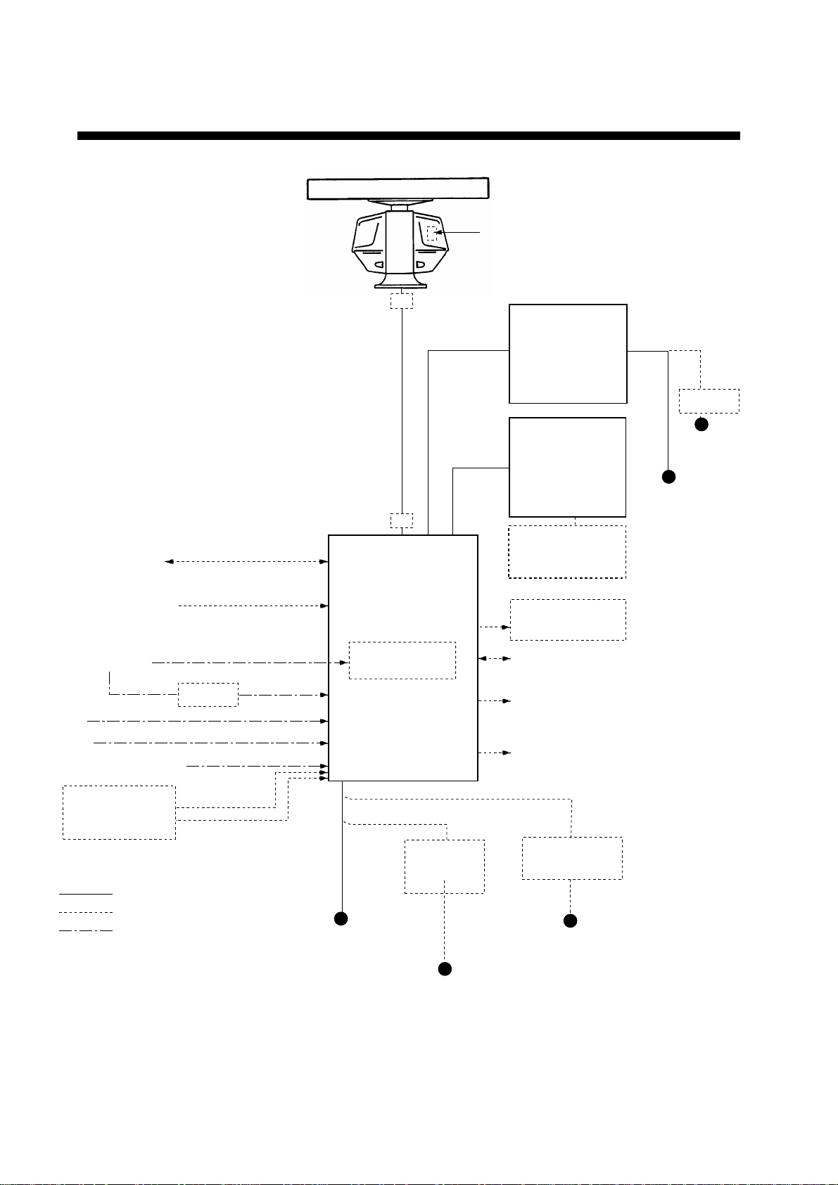
SYSTEM CONFIGURATION
Performance Monitor
ANTENNA UNIT
FAR-2117/2817: XN12AF-RSB-096-078
FAR-2127/2827: XN12AF-RSB-096-079
Navigator
Speed Log
Gyrocompass
AIS
HUB
Track Control Unit
XN12AF-RSB-097-078
XN20AF-RSB-096-078
XN20AF-RSB-097-078
XN24AF-RSB-096-078
XN24AF-RSB-097-078
XN12AF-RSB-097-079
XN20AF-RSB-096-079
XN20AF-RSB-097-079
XN24AF-RSB-096-079
XN24AF-RSB-097-079
IEC-61162-1 Serial Data
(Input/Output)
IEC-61162-1 Serial Data
(Input)
AD-100
JB
JB
PROCESSOR UNIT
RPU-013
Gyro Converter
GC-10
MONITOR UNIT
MU-201CR
(FAR-2117/2127)
or
MU-231CR
(FAR-2817/2827)
CONTROL UNIT
RCU-014
(Keyboard)
or
RCU-015
(Trackball)
Control Unit
RCU-016
(Remote)
Sub Display
Alarm
VDR
External Monitor
24 VDC
RU-3423
100/110/115
220/230 VAC
Ship's Mains
24 VDC
or
100-240 VAC
MEMORY CARD
INTERFACE UNIT
CU-100
: Standard
: Option
: Dockyard supply
xii
Ship's Mains
24 VDC
or
100-115 VAC/
220-230 VAC
1
φ
, 50-60 Hz
System configuration
DC spec
Rectifier
RU-3424
RU-1746B-2
100/110/115/
220/230 VAC
1
φ
, 50-60 Hz
AC spec
Transformer Unit
RU-1803
440 VAC
1
φ
, 50-60 Hz

SPECIFICATIONS
ANTENNA RADIATORS
1. Type Slotted waveguide array
2. Beamwidth
Radiator type XN12AF XN20AF XN24AF
Length 4 ft 6.5 ft 8 ft
Beamwidth(H) 1.8° 1.23° 0.95°
Beamwidth(V) 20° 20° 20°
Sidelobe ±10° -28 dB (all radiators)
Polarization Horizontal (all radiators)
3. Rotation 24 rpm or 42 rpm
RF TRANSCEIVER
1. Frequency 9410 MHz ±30 MHz (X-band)
2. Output power FAR-2117/2817: 12 kW
FAR-2127/2827: 25 kW
Unwanted emissions comply with ITU-R.
3. Range, Pulselength (PL) & PRF
Range scales PL (µs) PRF (Hz)
0.125, 0.25 0.07 3000
0.5 0.07/0.15 3000
0.75, 1.5 2 from 0.07/0.15/0.3 3000/1500
3 2 from 0.15/0.3/0.5/0.7 3000/1500
6 2 from 0.3/0.5/0.7/1.2 1500/1000
12, 24 2 from 0.5/0.7/1.2 1000/600
48, 96 1.2 600
Regular version has more intermediate ranges, also in km or sm.
4. IF 60 MHz, Log amp. BW 28/3 MHz
5. Noise figure 6 dB
6. Duplexer Ferrite circulator with diode limiter
DISPLAY UNIT
1. Screen Yellow or green echoes in 16 levels. Rasterscan non-interlace at 48.3
kHz hor, 60 Hz vert. R-type has yellow or green monochrome plus
3-color display according to echo strengths.
FAR-2117/2127
21” color LCD MU-201CR (399.36, 319.49 in mm)
Resolution: 1024 x 768 pixels
Effective radar diameter: 250 mm
FAR-2817/2827
23” color LCD MU-231CR (470.4, 352.8 in mm)
Resolution: 1024 x 768 pixels
Effective radar diameter: 340 mm
xiii

SPECIFICATIONS
v
2. Minimum range and
range discrimination 35 m
3. Range accuracy 1% of the maximum range of the scale in use or 30 m, whichever is
the greater
4. Bearing discrimination Better than 2.5°
5. Bearing accuracy ±1°
6. Presentation mode Head-up, Head-up TB, North-up, Course-up, TM sea or ground
stabilization
7. Plotting facilities ARPA
8. Radar map Nav lines, coastlines, buoys, etc. produced by operator. 3000 pts in
9. Guard zone Two GZ anywhere, anchor watch as well
10. Parallel index line Choice of 2, 4 or 6 lines
11. AIS IMO SN Circ.217, IEC 60945-5
●
Auto or Manual Acquisition: 100 targets in 0.2-32 nm
●
Auto tracking on all acquired targets
Radar mode, 6000 pts on IC card in Chart mode
INTERFACE
1. IEC 61162-1 Ed. 2 RSD, TTM, AIS related data, etc.
2. Compass Built-in interface (option) for sync signal (20-135 V, 50-400 Hz), or
stepper signal (20-135 VDC), any polarity, for Gyrocompass, GPS
compass SC-60/120 by IEC 61162^1
3. Speed IEC 61162-1, contact closure or 200/400/500 pulses/nm
4. Others Echo sounder, GPS navigator, Water temperature, etc.
POWER SUPPLY
1. DC version 24 VDC, 15.4 A max
2. AC version 115/230 VAC, 1ø, 50/60 Hz, 270 VA
440 VAC, 3ø, 60 Hz
ENVIRONMENTAL CONDITIONS
1. Ambient temperature (Complies with IEC 60945)
Indoor units -15°C to + 55°C
Antenna unit -25°C to + 70°C (Storage)
2. Relative humidity 95% or less at 40
3. Waterproofing Antenna unit: IPX6 (IEC 60529)
Indoor units: IPX2 (IEC 60529)
4. EMC Full compliance with IEC 60945 Ed. 3
(to 2 GHz cabinet radiation)
°
C
and 4
xi

1. RADAR OPERATION
1.1 Turning on the Power
The [POWER] switch is located at the left corner of the control unit. Open the
power switch cover and press the switch to turn on the radar system. To turn off
the radar, press the switch again. The screen shows the bearing scale and
digital timer approximately 15 seconds after power-on. The
three minutes of warm-up time. During this period the magnetron (transmitter
tube) is warmed for transmission. When the timer has reached 0:00, the
indication “ST-BY” appears at the screen center, meaning the radar is now ready
to transmit pulses.
In stand-by condition, markers, rings, map, charts, etc. are not shown. Further,
ARPA is cancelled and the AIS display is erased.
In warm-up and stand-by condition, you will see the message BRG SIG
MISSING because the antenna is not rotating; azimuth signal is not being sent to
the processor unit. ON TIME and TX TIME counts in hours and tenths of hour
appear at the screen center.
timer counts
down
1.2 Transmitter ON
After the power is turned on and the magnetron has warmed up, ST-BY appears
at the screen center, meaning the radar is ready to transmit radar pulses. You
may transmit by pressing the [STBY/TX] key on the full keyboard or roll the
trackball to choose the TX STBY box at the bottom left corner of the display and
then pushing the left button (above the trackball). The left-hand side of the
guidance box at the bottom right corner of the screen changes from TX to STBY.
TX
STBY
TX STBY box
STBY
/
Guidance
box
Radar display
1-1

1. RADAR OPERATION
The radar is initially set to previously used range and pulse length. Other
settings such as brilliance levels, VRMs, EBLs and menu option selections are
also set to previous settings.
The [STBY/TX] key (or TX STBY box) toggles the radar between STBY and
TRANSMIT status. The antenna stops in stand-by and rotates in transmit. The
magnetron ages with time resulting in a reduction of output power. It is highly
recommended that the radar be set to stand-by when not used for an extended
period of time.
Quick start
Provided that the radar was once in use with the transmitter tube (magnetron)
still warm, you can turn the radar into TRANSMIT condition without three
minutes of warm-up. If the [POWER] switch has been turned off by mistake or
the like and you wish to restart the radar promptly, turn on the [POWER] switch
not later than 10 seconds after power-off.
1-2

1.3 Control Unit
Two types of control units are available: RCU-014 which features a full keyboard
and trackball module and the RCU-105 which has function keys and trackball
module.
1. RADAR OPERATION
POWER
EBL rotary control VRM rotary control
21
EBL
OFFSET
CU/TM
RESET
VECTOR
MODE
0
BRILL
A/C SEAA/C RAIN
3
MODE
6
INDEX
LINE
9
TARGET
LIST
ENTER
MARK
GAIN
OFF
EBL
F1
F3 F4
ALARM
ACK
ON
F2
STBY
TX
BRILL
HL
OFF
45
OFF
CENTER
78
VECTOR
TIME
CANCEL
TRAILS
Control unit RCU-014
OFF
MENU
+
RANGE
Wheel
Left button Right button
ON
VRM
ACQ
TARGET
DATA
TARGET
-
CANCEL
Trackball
Trackball
Module
POWER
F1
F2
F3
F4
Wheel
Left button Right button
Trackball
Trackball
Module
Control unit RCU-015
1-3

1. RADAR OPERATION
Control description
Control Description
Control unit RCU-014
POWER Turns the system on and off.
EBL and VRM rotary controls Adjust EBL and VRM, respectively.
EBL ON, EBL OFF Turns the EBLs on and off, respectively.
F1-F4 Execute menu short cut assigned.
ALARM ACK Silences audible alarm.
STBY TX Toggles between stand-by and transmit.
BRILL Adjusts display brilliance.
A/C RAIN Suppresses rain clutter.
A/C SEA Suppresses sea clutter.
GAIN Adjusts sensitivity of the radar receiver.
HL OFF Temporarily erases the heading line while pressed.
EBL OFFSET Enables, disables the EBL offset. In menu operation, switches
polarity from North to South and East to West and vice versa.
MODE Chooses presentation mode.
OFF CENTER Shifts own ship position.
CU/TM RESET • Moves own ship position in 75% radius in stern direction.
• Resets the heading line to 0° in course-up and true motion
modes.
INDEX LINE Turns index lines on and off.
VECTOR TIME Chooses vector time (length).
VECTOR MODE Chooses vector mode, relative or true.
TARGET LIST Displays ARPA target list.
CANCEL TRAILS Cancels all target trails. In menu operation it clears line of data.
BRILL Adjusts brilliance of on-screen items.
ENTER MARK Enters marks; terminates keyboard input.
VRM ON, VRM OFF Turns the VRMs on and off, respectively
MENU Opens and closes the MAIN menu; closes other menus.
ACQ
RANGE Chooses radar range.
TARGET DATA Displays target data for ARPA or AIS target chosen with the
TARGET CANCEL Cancels tracking on ARPA, AIS or reference target chosen with
Control unit RCU-015
POWER Turns the system on and off.
F1-F4 Execute programmed function.
• Acquires a target for ARPA after choosing it with the
trackball.
• Changes a sleeping AIS target to an activated one after
choosing it with the trackball.
trackball.
the trackball.
1-4

1.4 Main Menu
l
To clear a line of numeric data:
Use the [CANCEL TRAILS] key.
l
Switch between plus and minus,
North and South or East and West:
Use the [2] key.
Useful keys in menu operation
You may access the MAIN menu from the full keyboard or by using the trackball.
In later sections only the procedure for menu operation by trackball is given.
Main menu operation by keyboard
1. Press the [MENU] key. The MAIN menu appears in the text area at the right
side of the screen.
[MAIN MENU]
1 [ECHO]
2 [MARK]
3 [ALARM]
4 [ARPA
5 [PLOTTER]
6 [CARD]
7 [NAV DATA]
8 [NAV LINE
9 [CUSTOMIZE
l
AIS]
l
WPT]
l
TEST]
1. RADAR OPERATION
Echo processing functions
Mainly turns markers on/off.
Sets guard alarm functions; outputs alarm signal.
Sets ARPA
Chart and track functions
Memory card functions
Turns nav data on/off.
Processes nav lines and waypoints.
Customizes operation; executes diagnostics.
and AIS functions.
2. Press the numeral key corresponding to the menu you wish to open. For
example, press the [2] key to open MARK menu.
3. Press the numeral key corresponding to the
item you wish to set.
4. Consecutively press the same numeral key
pressed at step 3 to choose appropriate
option and then press the [ENTER MARK]
key to register your selection.
5. Press the [MENU] key to close the menu.
MAIN menu
[MARK MENU]
1 BACK
2 OWN SHIP MARK
OFF/ON
3 STERN MARK
OFF/ON
4 INDEX LINE BEARING
REL/TRUE
5 INDEX LINE
1/2/3/6
6 INDEX LINE MODE
VERTICAL/HORIZONTAL
7
8 EBL OFFSET BASE POINT
STAB GND/STAB HDG/
STAB NORTH
9 EBL CURSOR BEARING
REL/TRUE
0 RING
OFF/ON
MARK menu
1-5

1. RADAR OPERATION
Main menu operation by trackball
1. Roll the trackball to choose the MENU box at the right side of the screen. The
guidance box at the bottom right corner (see the illustration at the bottom of
the next page for location) now reads “DISP MAIN MENU.”
MENU
Menu box
2. Push the left button to display the MAIN menu.
[MAIN MENU]
1 [ECHO]
2 [MARK]
3 [ALARM]
4 [ARPA
5 [PLOTTER]
6 [CARD]
7 [NAV DATA]
8 [NAV LINE
9 [CUSTOMIZE
l
AIS]
l
WPT]
l
TEST]
MAIN menu
3. Roll the wheel to choose the menu you wish to open and then push the
wheel or the left button. For example, choose the 2 [MARK] menu and then
push the wheel or the left button.
[MARK MENU]
1 BACK
2 OWN SHIP MARK
OFF/ON
3 STERN MARK
OFF/ON
4 INDEX LINE BEARING
REL/TRUE
5 INDEX LINE
1/2/3/6
6 INDEX LINE MODE
VERTICAL/HORIZONTAL
7
8 EBL OFFSET BASE POINT
STAB GND/STAB HDG/
STAB NORTH
9 EBL CURSOR BEARING
REL/TRUE
0 RING
Echo processing functions
Mainly turns markers on/off.
Sets guard alarm functions; outputs alarm signal.
Sets ARPA
Chart and track functions
Memory card functions
Turns nav data on/off.
Processes nav lines and waypoints.
Customizes operation; executes diagnostics.
OFF/ON
and AIS functions.
1-6
MARK menu
4. Roll the wheel to choose item desired and then push the wheel or the left
button.
5. Roll the wheel to choose option desired and then push the wheel or the left
button to register your selection.
6. Push the right button to close the menu. (Several pushes may be necessary
depending on the menu used.)
1. RADAR OPERATION
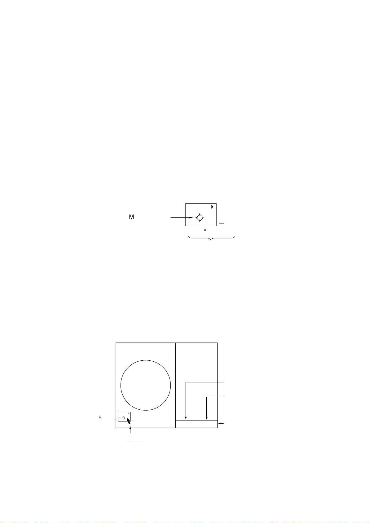
1.5 Operation Using the On-Screen Boxes
All radar functions can be accessed by using the trackball alone. This is done by
choosing the appropriate on-screen box with the trackball and operating the
trackball module to choose item and option. (See paragraph 1.9 for location of all
on-screen boxes.) On-screen boxes come in two varieties: Function selection
and function selection w/pop-up menu. On-screen boxes of the latter type have
“►” at the right side of their boxes, as in the MARK box shown below.
To operate the radar using on-screen boxes, do the following:
1. Roll the trackball to place the trackball marker inside the box desired.
Note: The trackball marker changes its configuration according to its location.
It is an arrow when placed outside the effective display and a cursor
(+) when inside the effective display. See the illustration on the next
page for further details.
For example, choose the MARK box, which is at the bottom left corner.
MARK 4
Mark type last
selected, mark
number
Bearing and range from
own ship to origin mark
1
> +
162.5°T 11.7
NM
MARK box
When a box is correctly selected, its color changes from green to yellow
(default colors) and the guidance box at the bottom right corner shows
operational guidance. The operational guidance shows the function of the left
and right buttons, with a diagonal line separating the information. For the
MARK box, for example, the operational guidance is “MARK SELECT /
MARK MENU.” In this case you would push the left button to choose a mark
or push the right button to open the MARK menu.
Function of left button
Function of right button
MARK Box
MARK 4
1
> +
Arrow
For choosing
on-screen box
MARK
SELECT
MARK
/
MENU
Guidance box
Guidance box (Example: guidance for MARK box)
1-7
1. RADAR OPERATION
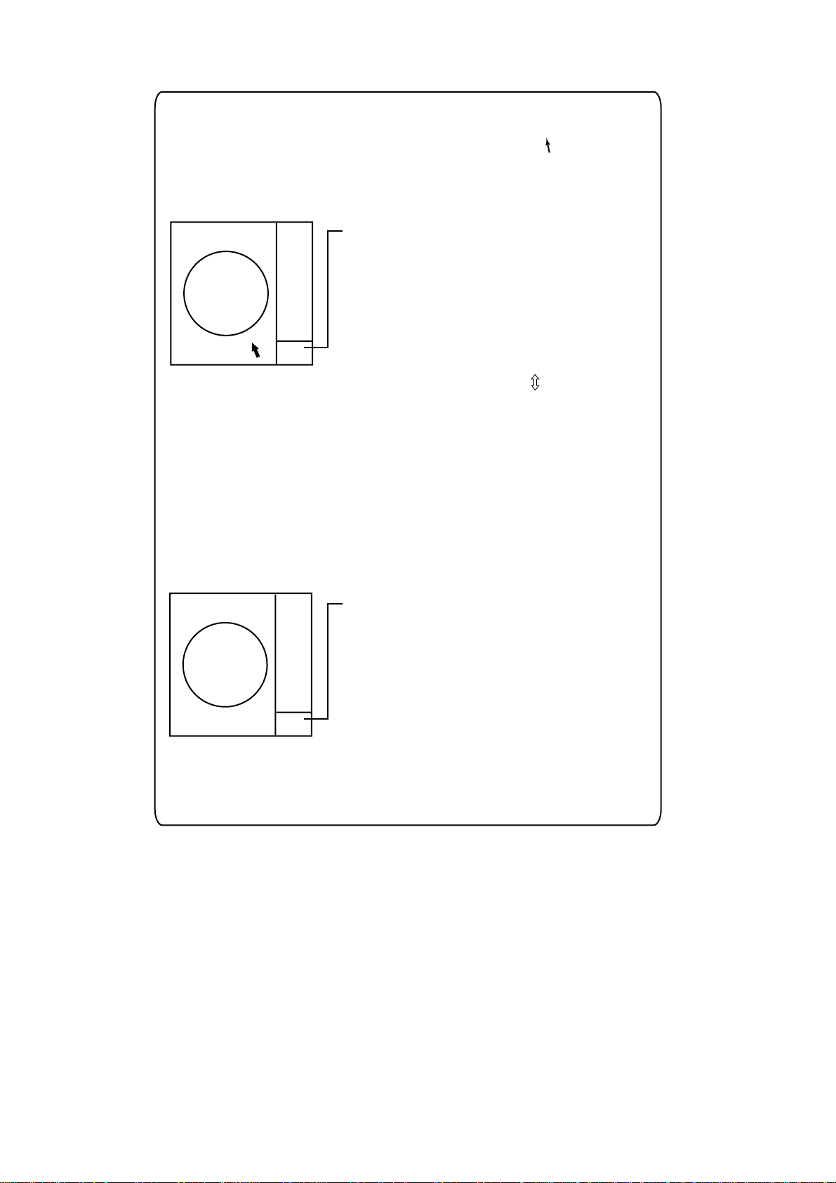
Trackball marker location and guidance box indication
The trackball marker is either a cursor (+) or an arrow ( ) depending
on whether it is within or outside the display area, respectively.
Further, the indication in the guidance box changes according to
trackball marker location.
Trackball marker is out of
effective display area
(incl. text area) and
not selecting a box:
The trackball marker is
an arrow
Guidance box reads
"JUMP CURSOR / DISP MENU."
Push the left button to choose the on-screen
box closest to the arrow or push the right
button to display the MAIN menu.
To choose boxes successively, push the wheel
when the guidance box reads as above.
Then, the nearest box is selected and marked
with the double-ended arrow ( ) and the
guidance box reads
"JUMP FORWARD / JUMP BACKWARD."
Hit the left button to go to the box below or
adjacent to the currently selected box or hit
the right button to go to the box above or
adjacent to the currently selected box.
Continue pushing a button to choose boxes
successively. This is convenient for operation
under heavy pitching and rolling. To cancel this
feature, push the wheel when the guidance box
reads as above.
Guidance box reads
"TRGT DATA & PLOT / CURSOR MENU."
In this condition you may access cursor-operated
+
Trackball marker is within
effective display area:
The trackball marker is
a cursor
functions, by hitting the left button for direct
selection of function or the right button to choose
desired functions from the CURSOR menu. For
further details about the CURSOR menu,
see paragraph 1.6.
2. Push the left button (or roll the wheel depending on the box) until the desired
option is displayed in the box.
Note: When you chose an on-screen box’s option by rolling the wheel, the
box and its contents turn red. This simply indicates that the chosen
setting is different from the currently active setting. To change the
setting, push the wheel or the left button. If neither the wheel nor the
left button is pushed within about 30 seconds after operating the wheel,
the previous setting is automatically restored.
1-8

1. RADAR OPERATION
3. The pop-up menu attached to the MARK box is the MARK menu. To open
the menu, push the right button. The menu opens in the text area at the right
side of the screen.
[MARK MENU]
1 ORIGIN MARK STAB
GND/SEA
2
ORIGIN MARK(No.)/
ORIGIN MARK(SYMBOL)/
MAP MARK/
WP 1~50/
WP 51~100/
WP 101~150/
WP 151~200/
OWN SHIP SHAPE
9 MAP DISPLAY
OFF/ON
0 MAP MARK COLOR*
RED/GRN/BLU/YEL/
CYA/MAG/WHT
* Not available
on IMO radar.
MARK menu
Note: Any menu may be operated from the full keyboard or the trackball, or a
combination of the two in case of Control Unit RCU-014. Note that in
later sections only the procedure for menu operation by the
trackball is given.
4. Roll the wheel to choose item desired and then push the wheel or the left
button. Selected item is initially shown in reverse video and changes to
normal video and circumscribed when the wheel or the left button is pushed.
5. Roll the wheel to choose option desired and then push the wheel or the left
button. Selected option is initially shown in reverse video and changes to
normal video and circumscribed when the wheel or the left button is pushed.
6. Push the right button to close the menu. (On some menus several presses of
the right button are required to close the menu.)
1-9

1. RADAR OPERATION
1.6 Cursor Menu
Functions which require the use of the cursor, such as EBL offset and zoom,
may be activated directly from the guidance box or from the CURSOR menu,
either method with the cursor inside the effective display area. Below is the
procedure for choosing a cursor-related function from the CURSOR menu. In
later sections only the procedure for selection from the guidance box is given.
1. Roll the trackball to place the cursor inside the effective display area.
2. Roll the wheel to show “TARGET DATA & ACQ / CURSOR MENU” in the
guidance box.
3. Push the right button to show the CURSOR menu.
[CURSOR MENU]
2 ↓
TARGET DATA & ACQ/
TARGET CANCEL/
ACQ/
REF MARK/
EBL OFFSET/
ZOOM/
MARK DELETE/
CHART ALIGN
CURSOR menu
4. Roll the wheel to choose 2 MARK KID and then push the wheel or the left
button.
5. Roll the wheel to choose function desired and then push the wheel or the left
button.
Note: For operation from the keyboard, you may press the [2] key to choose
a function in top-to-bottom order or the [8] key to choose in reverse
order.
Cursor Menu item Description
TARGET DATA & ACQ ARPA: Acquires ARPA target; displays data for chosen
ARPA target.
AIS: Activates sleeping AIS target; display data for chosen
AIS target.
TARGET CANCEL ARPA: Cancels tracking on chosen ARPA target.
AIS: Sleeps chosen AIS target.
ACQ ARPA: Acquires chosen echo.
AIS: Activates chosen AIS target.
REF MARK Inscribes reference mark, for target-based speed input.
EBL OFFSET Offsets EBL, to measure range and bearing between two
targets.
OFF CENTER Shifts screen center to chosen location.
ZOOM Zooms chosen location.
MARK DELETE Deletes chosen mark (plotter mark, origin mark or
waypoint mark).
CHART ALIGN Aligns chart with radar picture.
1-10
6. Push the right button to close the menu. The guidance box shows “XX /
EXIT.” (XX = function chosen)
7. Roll the trackball to place the cursor where desired.
8. Push the left button to execute the function selected at step 5.
9. To quit the function selected, push the right button when the guidance box
shows “XX / EXIT.” (XX = function chosen at step 5)
1.7 Monitor Brilliance
The brilliance of the entire screen should be adjusted according to lighting
conditions. Monitor brilliance should be adjusted before adjusting relative
brilliance levels on the BRILL menu to be explained later.
Note: The brilliance of a PC monitor cannot be adjusted from the radar. See the
owner’s manual of the PC monitor for how to adjust its brilliance.
By keyboard
1. RADAR OPERATION
Operate the [BRILL] control on the control unit to adjust brilliance. Turn it
clockwise to increase brilliance; counterclockwise to decrease brilliance. Watch
the BRILL box (see illustration below) to know current brilliance level.
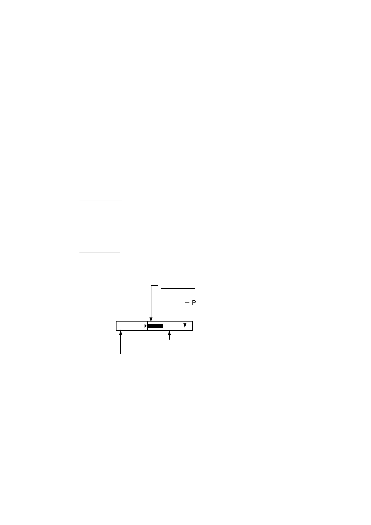
By trackball
1. Roll the trackball to place the arrow on the brilliance level bar in the BRILL
box at the bottom left corner of the screen.
Brilliance bar
Shows brilliance level.
Place arrow inside box
to adjust screen brilliance.
BRILL1 4
Brillance, color set no.
(For details, see para. 1.50.)
26
Brilliance level
BRILL box
2. Roll the wheel downward to increase brilliance or roll it upward to decrease
brilliance. The length of the brilliance bar increases or decreases with
operation of the wheel.
Note: If nothing appears on the screen at power-up when using the mini
keyboard (Control Unit RCU-015) or when the radar is in stand-by, press
and hold down any key except the power switch for four seconds to
automatically set up for medium display brilliance.
1-11

1. RADAR OPERATION
1.8 Choosing the Display Mode
This radar has two display modes: Radar and Radar + Plotter. Choose a display
mode as below. Note that a display mode cannot be chosen when the menu is
open.
1. Roll the trackball to place the arrow in the DISPLAY MODE box at the top of
the screen.
DISPLAY
XX*
* XX = display mode
(RADAR, +PLOTTER)
DISPLAY MODE box
2. Push the left button to choose appropriate mode:
RADAR: Radar picture
+PLOTTER: Radar picture + plotter picture (incl. chart)
4
1-12
 Loading...