

Furuno USA 9ZWRTR057A, 9ZWRTR059A, 9ZWRTR064A User Manual
4. AIS OPERATION
4. Use the Cursorpad (S) to select [Yes] and press the ENTER key. All lost targets
symbols are erased from the screen and the long beep sounds.
5. Press the MENU key to close the menu.
4.15 Symbol Color
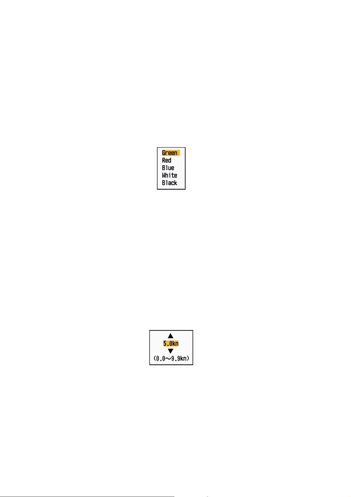
You can select the AIS symbol color among Green, Red (unavailable in the [IEC] or
[Russian-River] purpose), Bl ue, White or Black.
1. Press the MENU key to open the menu.
2. Use the Cursorpad (S or T) to select [AIS] and press the ENTER key.
3. Use the Cursorpad (S or T) to select [Color] and press the ENTER key.
Color options
4. Use the Cursorpad (S or T) to select the color and press the ENTER key.
5. Press the MENU key to close the menu.
Note: Symbols can not be shown in the same color as the background color .
4.16 How to Ignore Slow Targets
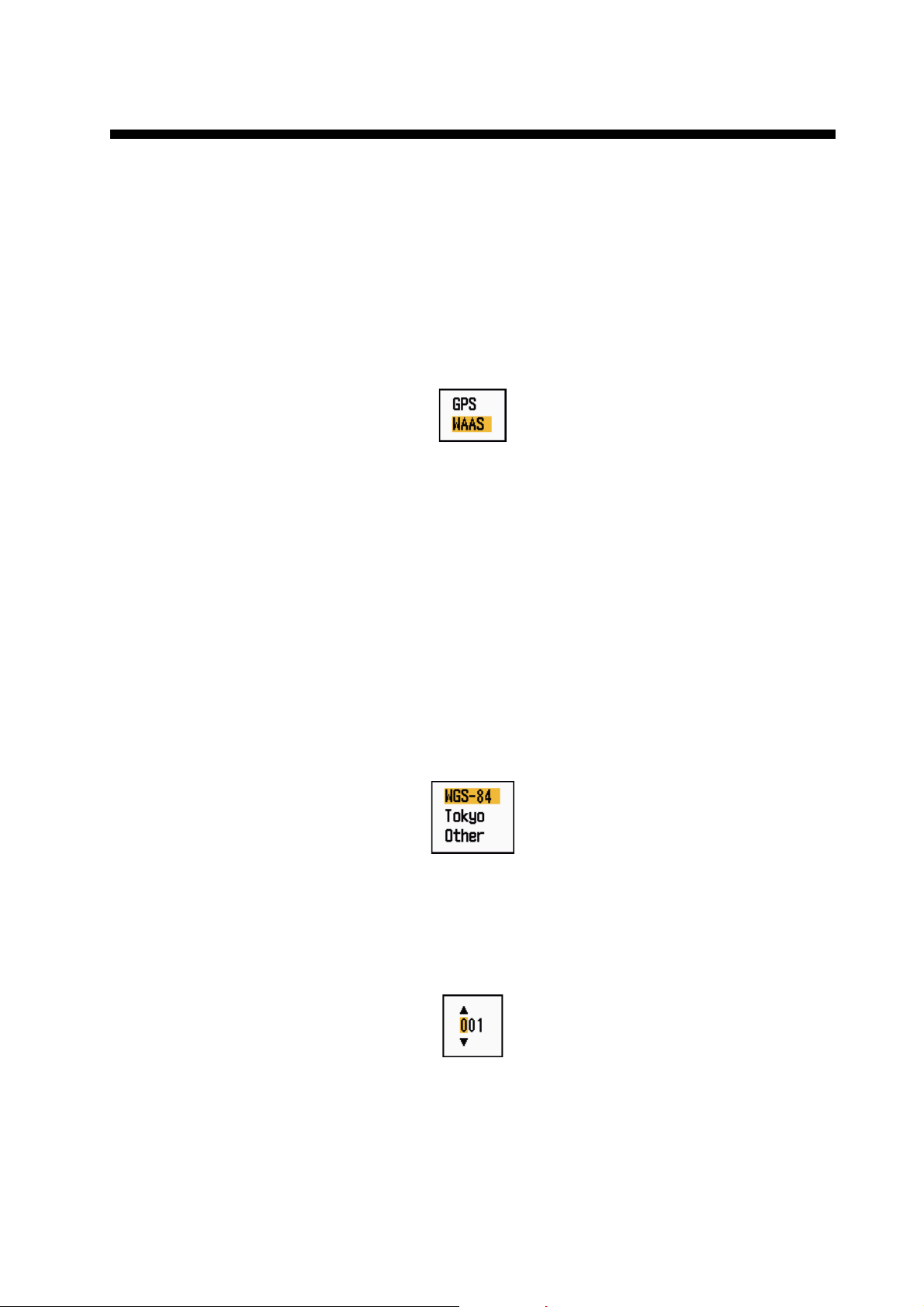
You can prevent activation of the CPA/TCPA alarm against AIS targets that are traveling at a speed lower than set here . The AIS symbols ar e not affect ed by this set ting.
1. Press the MENU key to open the menu.
2. Use the Cursorpad (S or T) to select [AIS] and press the ENTER key.
3. Use the Cursorpad (S or T) to select [Ignore Slow Target s] and press the ENTER
key.
4-10
Ignore Slow Targets setting window
4. Use the Cursorpad (S or T) to select speed (0.0 - 9.9 kn) and press the ENTER
key.
5. Press the MENU key to close the menu.
5. GPS OPERATION
If the FURUNO GPS Navigator GP-320B is connected to this radar, you can set GP320B from this radar.
5.1 Navigator Mode
1. Press the MENU key to open the menu.
2. Use the Cursorpad (S or T) to select [GPS] and press the ENTER key.
3. Use the Cursorpad (S or T) to select [Mode] and press the ENTER key.
Mode options
4. Use the Cursorpad (S or T) to select [GPS] or [WAAS] then press the ENTER
key.
5. Press the MENU key to close the menu.
5.2 Datum
Select the type of datum which matches the paper charts you use for navigation. Select [WGS-84] if the radar is connected to an AIS Transponder.
1. Press the MENU key to open the menu.
2. Use the Cursorpad (S or T) to select [GPS] and press the ENTER key.
3. Use the Cursorpad (S or T) to select [Datum] and press the ENTER key.
4. Use the Cursorpad (S or T) to select the type of datum and press the ENTER
key. If you select [WGS-84] or [Tokyo], go to step 7. If you select [Other], go to the
next step.
5. Use the Cursorpad (S or T) to select [Datum No] and press the ENTER key.
Datum options
Datum No setting window
6. Use the Cursorpad (S or T) to select the datum number and press the ENTER
key. (The setting range is 001 - 192 and 201 - 254. Refer to the appendix 2 “GEODETIC CHART LIST”.)
7. Press the MENU key to close the menu.
5-1
5. GPS OPERATION
5.3 WAAS Setup
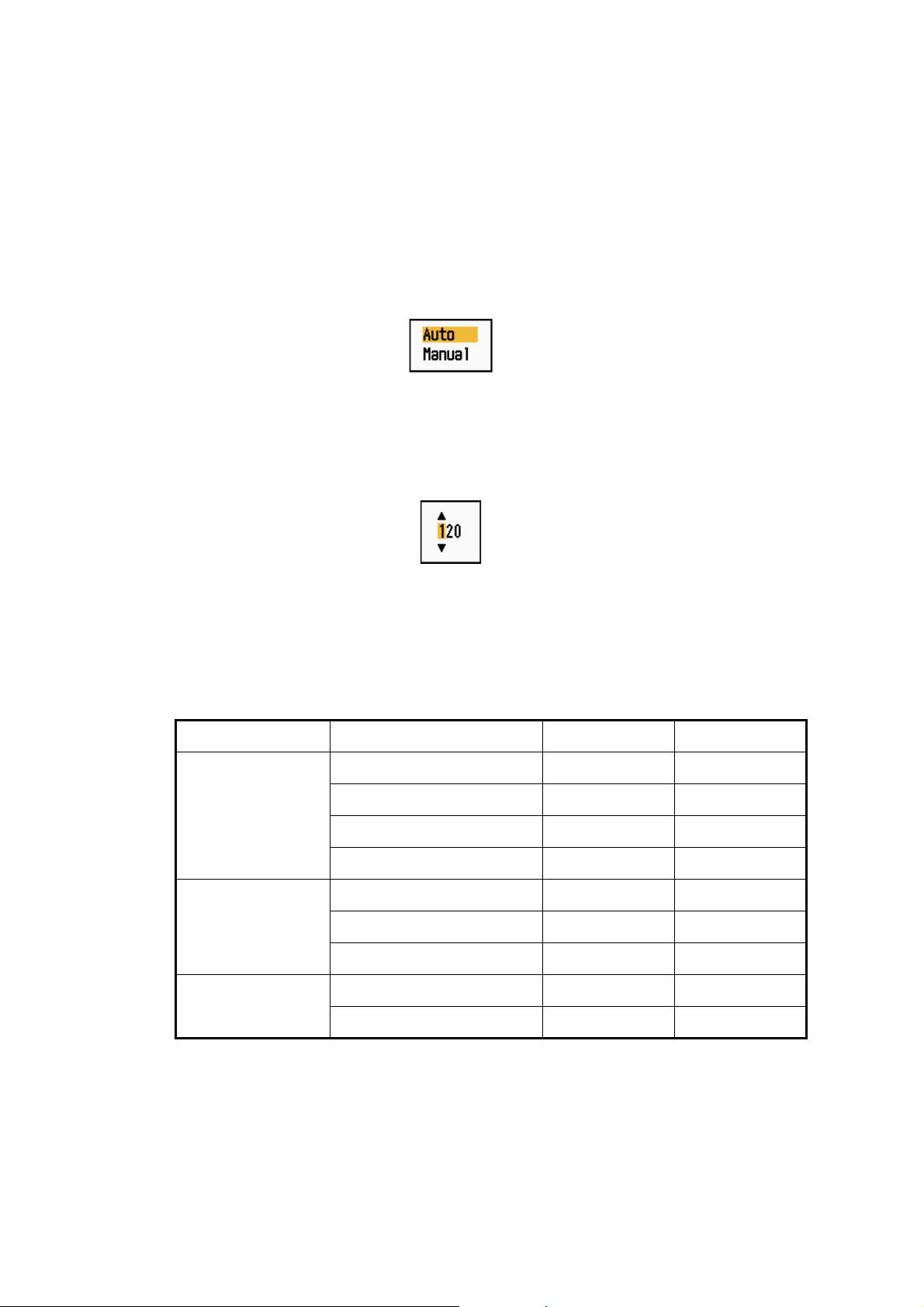
Geostationary satellites, the type used with WAAS, provide more accurate position
data when compared to GPS. These satellites can be track ed automatic ally or manually. Auto tracki ng automatically searche s for the best geosta tionary satellite from your
current position.
1. Press the MENU key to open the menu.
2. Use the Cursorpad (S or T) to select [GPS] and press the ENTER key.
3. Use the Cursorpad (S or T) to select [WAAS] and press the ENTER key.
4. Use the Cursorpad (S or T) to select [Auto] or [Manual] then press the ENTER
key. If you select [Auto], go to step 7. If you select [Manual], go to the next step.
5. Use the Cursorpad (S or T) to select [WAAS No] and press the ENTER key.
WAAS options
WAAS No setting window
6. Use the Cursorpad (S or T) to select WAAS number and pre ss the ENTER key.
(The setting range is 120 - 158. Refer to the followi ng table.)
7. Press the MENU key to close the menu.
Provider Satellite type Longitude Satellite No.
WAAS Inmarsat-3-F4 (AOR-W) 142°W 122
Inmarsat-3-F3 (POR) 178°E 134
Intelsat Galaxy XV 133°W 135
TeleSat Anik F1R 107.3°W 138
EGNOS Inmarsat-3-F2 (AOR-E) 15.5°W 120
Artemis 21.5°E 124
Inmarsat-3-F5 (IOR-W) 25°E 126
MSAS MTSAT-1R 140°E 129
MTSAT-2 145°E 137
5-2
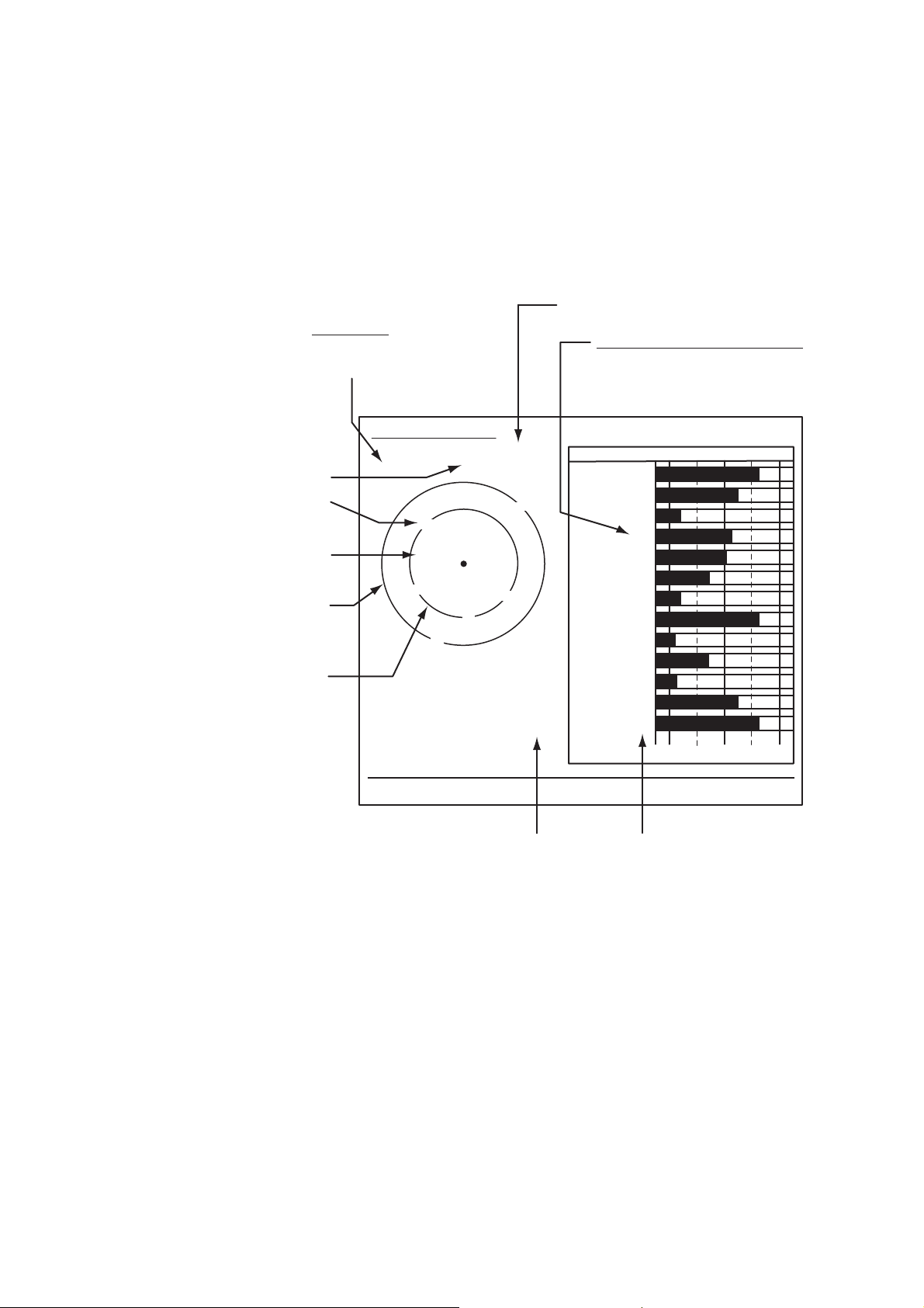
5.4 Satellite Monitor
The Satellite Monitor provides the information about GPS and WAAS satellites. See
your GPS navigator's owner's manual for detai led information.
1. Press the MENU key to open the menu.
2. Use the Cursorpad (S or T) to select [GPS] and press the ENTER key.
3. Use the Cursorpad (S or T) to select [Satellite Monitor] and press the ENTER
key.
GPS mode
2D, 3D,
W2D, W3D
5. GPS OPERATION
DOP (Dilution of Precision, 0.0 - 99.0)
SNR of tracked GPS satellites
Satellites whose SNR is above
40 are used to fix position.
North marker
GPS satellite no.*
WAAS satellite
Satellites in ring
have elevation
angle of 5°
Satellites in ring
have elevation
angle of 45°
* Satellites used to fix
position are shown in red.
Satellite Monitor
W3D
07
W
13
13
16
09
01
18
31
19
08
DOP
1.5
24
12
06
Altitude
15m
WAAS
N
30 40 50
01
01GPS
31
12
18
19
06
07
09
24
08
16
13
122
[MENU]: Close MENU [ENTER]: Close this window
Altitude of
GPS antenna
SNR of tracked
WAAS satellite
from sea
surface
SNRSatellite No.
Satellite monitor
4. Press the ENTER key to close only the satelli te monitor display.
5-3
5. GPS OPERATION
5.5 Cold Start
Cold start, which clears the Almanac from the GPS receiver, can be necessary in the
following conditions:
• If you have turned off the power of the GPS receiver for a long time.
• The ship has moved far away from the previous fixing position (e.g., more than 500
km).
• Other reason that prevents the receiver from finding its position within five minutes
after you turn on the power.
To do cold start, do the following:
1. Press the MENU key to open the menu.
2. Use the Cursorpad (S or T) to select [GPS] and press the ENTER key.
3. Use the Cursorpad (S or T) to select [Cold Start] and press the ENTER key.
Cold Start options
4. Use the Cursorpad (S) to select [Yes] and press the ENTER key. After processing
cold start, the long beep sounds. (To stop cold start, press the CANCEL/HL OFF
key instead of the ENTER key.)
5. Press the MENU key to close the menu.
5-4
6. MAINTENANCE, TROUBLESHOOTING
This chapter has information about maintenance and troubleshooting that the user
can follow to care for the equipment.
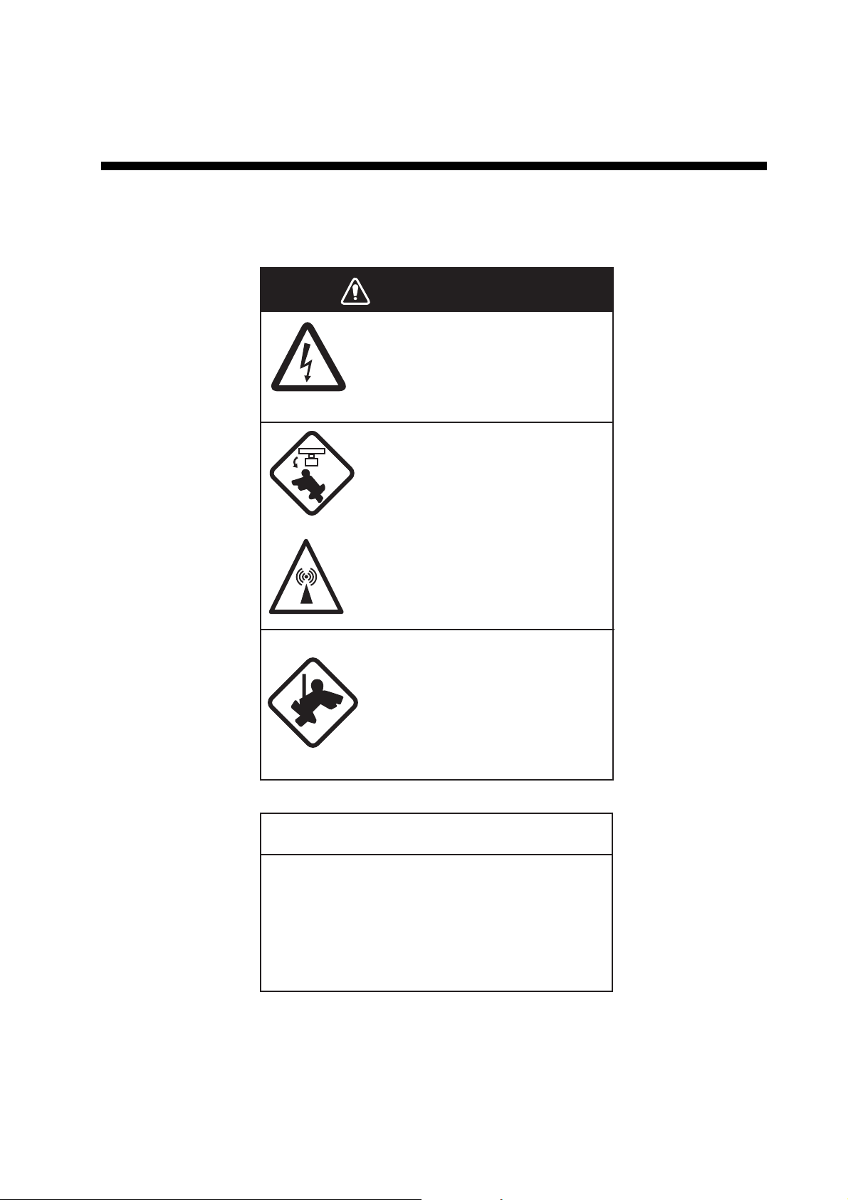
WARNING
ELECTRICAL SHOCK HAZARD
Do not open the equipment.
Only qualified personnel can work
inside the equipment.
Turn off the power before you
service the antenna unit. Post
a warning sign near the power
switch not to turn on the power
while you service the antenna
unit.
Prevent the potential risk of being
struck by the rotating antenna and
exposure to RF radiation hazard.
When you work on the antenna
unit, wear a safety belt and hard
hat.
Serious injury or death can result
if a person falls from the radar
antenna mast.
NOTICE
Do not apply paint, anti-corrosive sealant
or contact spray to plastic parts or
equipment coating.
Those items contain products that can
damage plastic parts and equipment coating.
6-1
6. MAINTENANCE, TROUBLESHOOTING
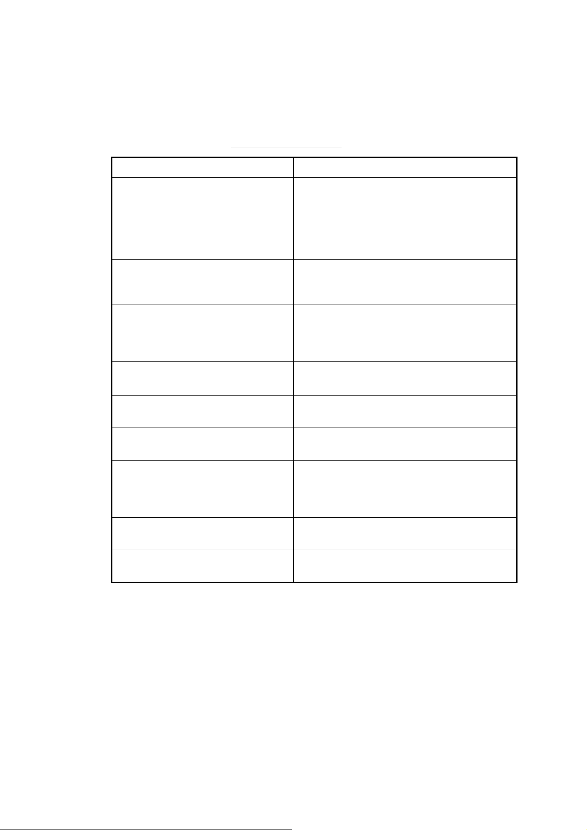
6.1 Preventive Maintenance
Regular maintenance helps keep your equipment in good condition and prevents future problems. Check the items shown in the table below to help keep your equipment
in good condition for years to come.
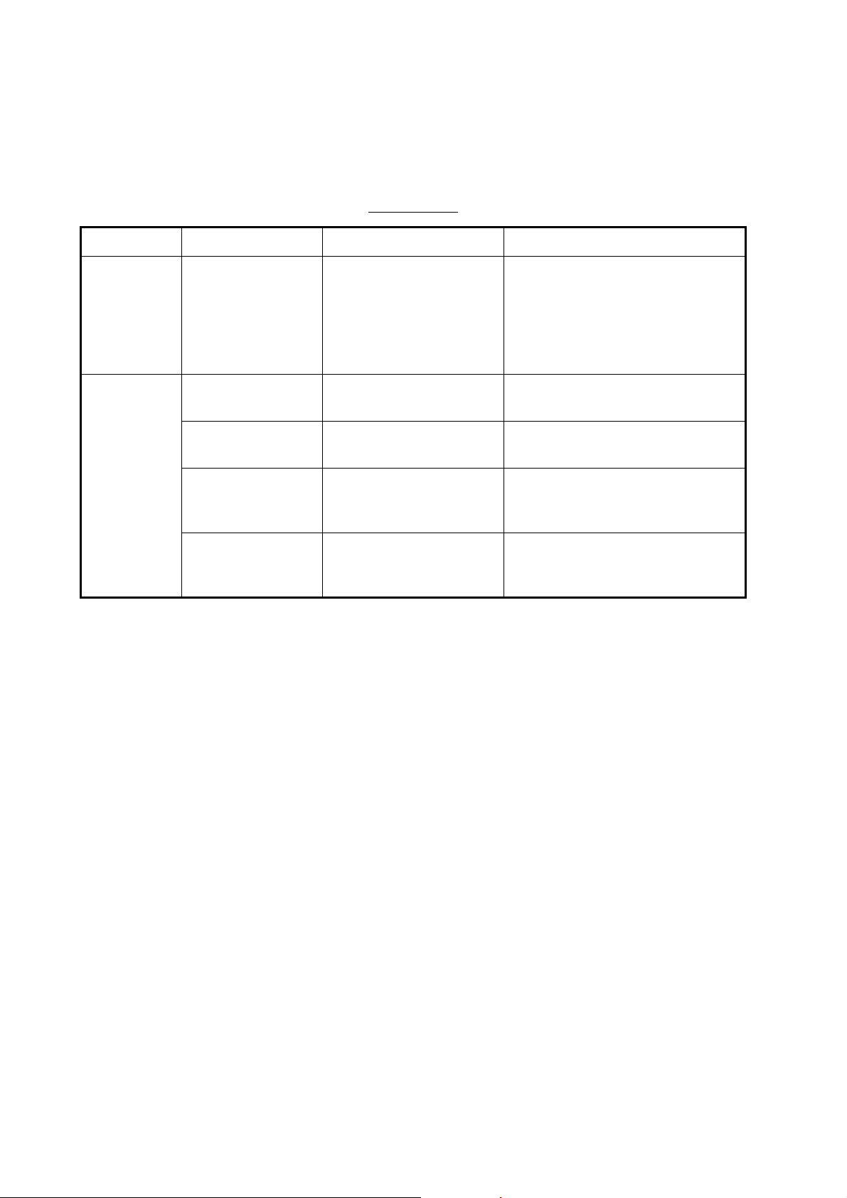
Maintenance
Interval Item Check point Remedy
When
necessary
3 to 6
months
LCD Dust on the LCD Remove the dust from the LCD
with the tissue paper and an LCD
cleaner. To remove dirt or salt, use
the LCD cleaner. Change the tissue paper often so as not to
scratch the LCD.
Ground terminal on
display unit
Display unit
connectors
Exposed nuts and
bolts on the antenna unit
Antenna radiator Check for dirt and cracks
Check for tight connection and rust.
Check for tight connection.
Check for corroded or
loosened bolts.
on the radiator surface.
Tighten or replace as necessary.
Tighten if the connectors are loosened.
Clean and repaint as necessary.
Use sealing compound instead of
paint.
Clean radiator surface with freshwater-moistened cloth. Do not use
plastic solvents to clean.
6-2
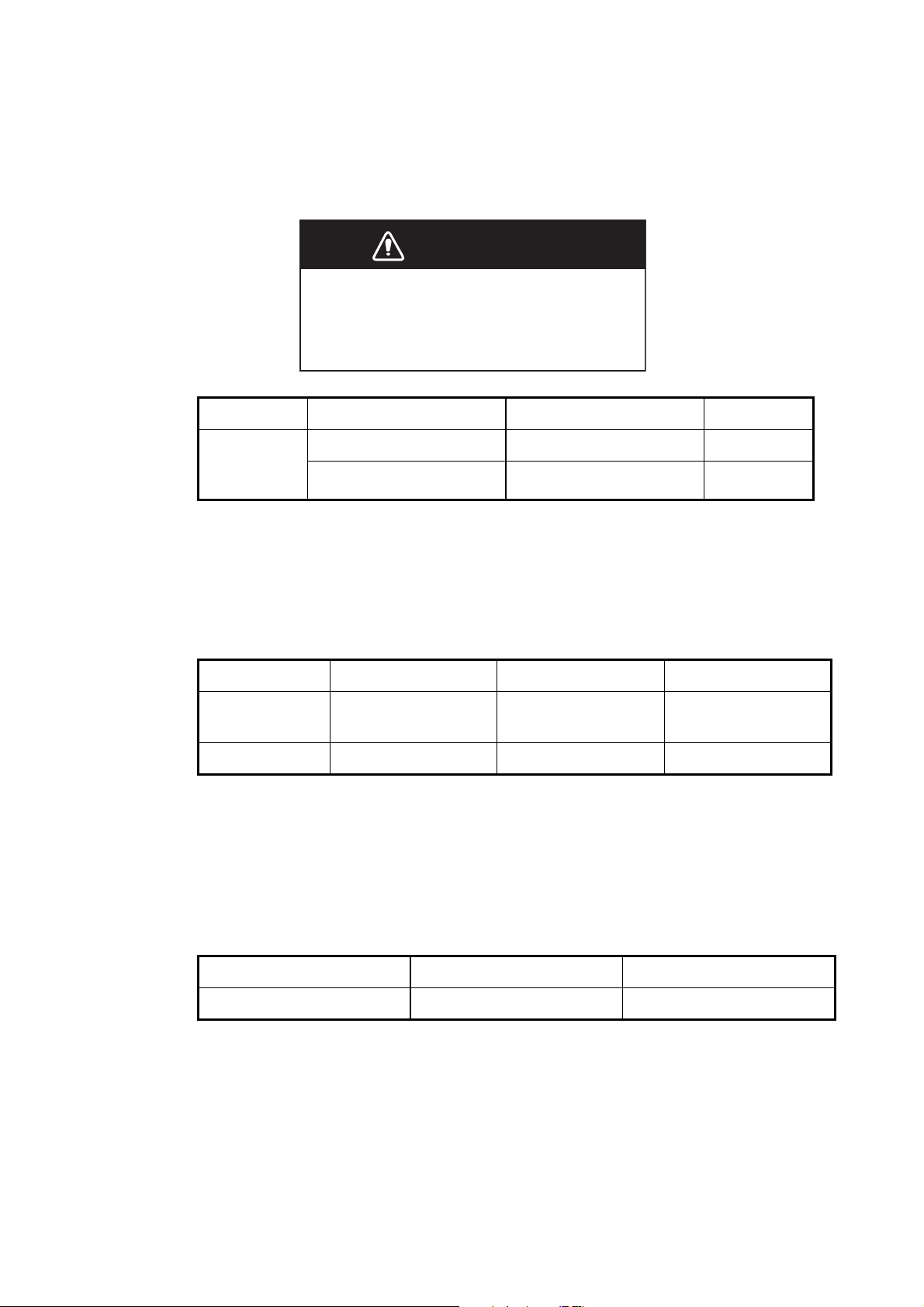
6.2 Fuse Replacement
The fuse on the power cable protects the equipment from overcurrent and equipment
fault. If the fuse blows, find the cause before you replace the fuse. Use the correct
fuse. A wrong fuse can damage the equipment.
WARNING
Use the correct fuse.
A wrong fuse can damage the equipment
and cause fire.
Unit Type Code No. Remarks
6. MAINTENANCE, TROUBLESHOOTING
Display unit
(fitted on
power cable)
FGB0 125V 10A PBF 000-155-826-10 12 VDC
FGB0-A 125V 5A PBF 000-155-853-10 24 VDC
6.3 Magnetron Life
When the life of the magnetron is reached, the targets do not appear on the display.
If long-range performance appears to have decreased, contact a FURUNO agent or
dealer about replacement of the magnetron.
Model Magnetron type Code No. Estimated life
MODEL 1835
MODEL 1935
MODEL 1945 MAF1422B 000-158-788-11 Approx. 3,000 hours
E3571 000-087-300 Approx. 2,000 hours
6.4 LCD Backlight Life
The life of the LCD backlight, which provides illumination for the LCD, is approximately
4,800 hours at 25°C (ambient temperature). The display brilliance cannot be raised
when the backlight has worn out. When brilliance cannot be raised, have a qualified
technician replace the backlight.
Name Type Code No.
Lamp holder complete set 104LHS46 000-160-949-10
6-3
6. MAINTENANCE, TROUBLESHOOTING
6.5 Simple Troubleshooting
This section provides simple troubleshooting procedures which the user can follow to
restore normal operation. If you cannot restore normal operation, do not check inside
the unit. Have a qualified technician check the equipment.
Simple troubleshooting
Problem Remedy
You cannot turn on the power. • Check for blown fuse.
• Check that the power connector is fastened.
• Check for corrosion on the power cable con-
• Check for damaged power cable.
• Check battery for correct voltage output.
nector.
There is no response when a key is
pressed.
The power is on and you operated the
STBY/TX key to transmit. The marks
and letters appear, but no echo appears.
Tuning is correctly adjusted, but
sensitivity is poor.
The range is changed, but radar picture does not change.
Poor discrimination in range because
of many echoes from the waves.
The true motion presentation is not
working correctly.
The range rings are not displayed. Check that the setting of [Rings Brill] in the
Turn off and on the power. If you do not get a
response, the key is damaged. Contact your
dealer for instructions.
Check that the antenna cable is fastened.
Replace the magnetron. Contact your dealer.
• Try to hit the RANGE key again.
• Turn off and on the display unit.
Adjust A/C SEA control.
• Check that the setting of [Display Mode] in
the [Display] menu is set to [True Motion].
• Check if the heading and position data are input and correct.
[Brill/Color] menu is set to other than [Off].
6-4
Target is not tracked correctly because of sea clutter.
Adjust A/C SEA and A/C RAIN controls.
6. MAINTENANCE, TROUBLESHOOTING
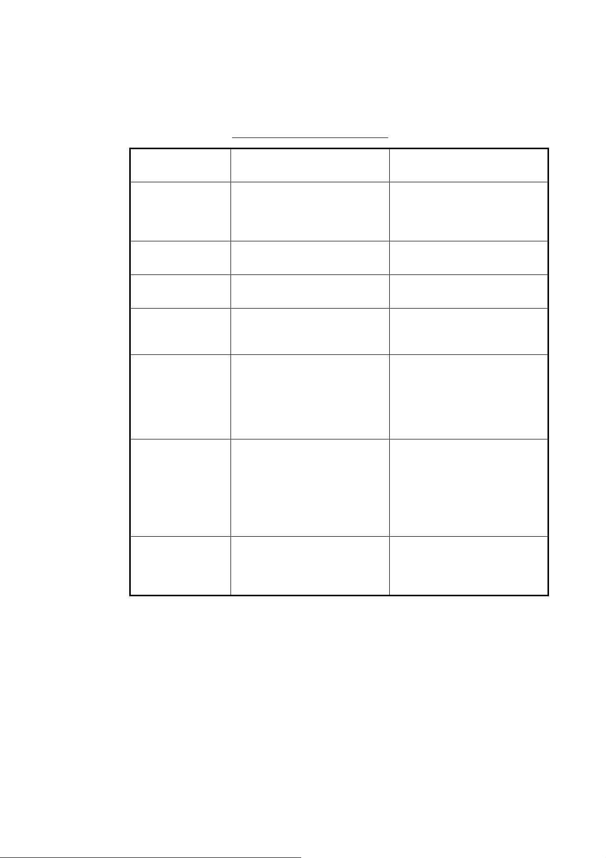
6.6 Advanced-level Troubleshooting
This section describes how to cure hardware and software troubles which the qualified
service persons must do.
Advanced-level troubleshooting
Problem
Power cannot be
turned on.
Brilliance adjusted
but no picture.
Antenna not rotating.
Data and marks
not displayed in
transmit.
Set GAIN to maximum with A/C SEA
set at minimum.
Marks and indications appear but no
noise or echo.
Marks, indications
and noise appear
but no echo.
(Transmission leak
representing your
ship position is absent.)
Probable cause or
check points
1) Mains voltage/polarity
2) Power supply board
1) SPU Board 1) Replace SPU board.
1) Antenna drive mechanism 1) Replace the antenna drive
1) SPU board 1) Replace SPU board.
1) Signal cable between antenna and display unit
2) IF amplifier
3) Video amplifier board
1) Magnetron
2) Modulator board
3) SPU board
1) Correct the wiring and input
voltage.
2) Replace power supply
board.
mechanism.
1) Check continuity and isolation of coaxial cable.
2) Replace IF amplifier.
3) Check coax line for fasten
connection. If connection is
good, replace SPU board.
1) Check magnetron current.
2) Replace modulator bo ar d .
3) Replace SPU board.
Remedy
Picture not updated or picture
freeze-up.
1) Bearing signal generator
2) SPU board
3) Video freeze-up
1) Check that signal ca bles
are fastened.
2) Replace SPU board.
3) Turn off and on the radar.
6-5
 Loading...