

Furuno USA 9ZWRTR051, 9ZWRTR070, 9ZWRTR058 User Manual
3. PLOTTER OPERATION
3.1 Plotter Displays
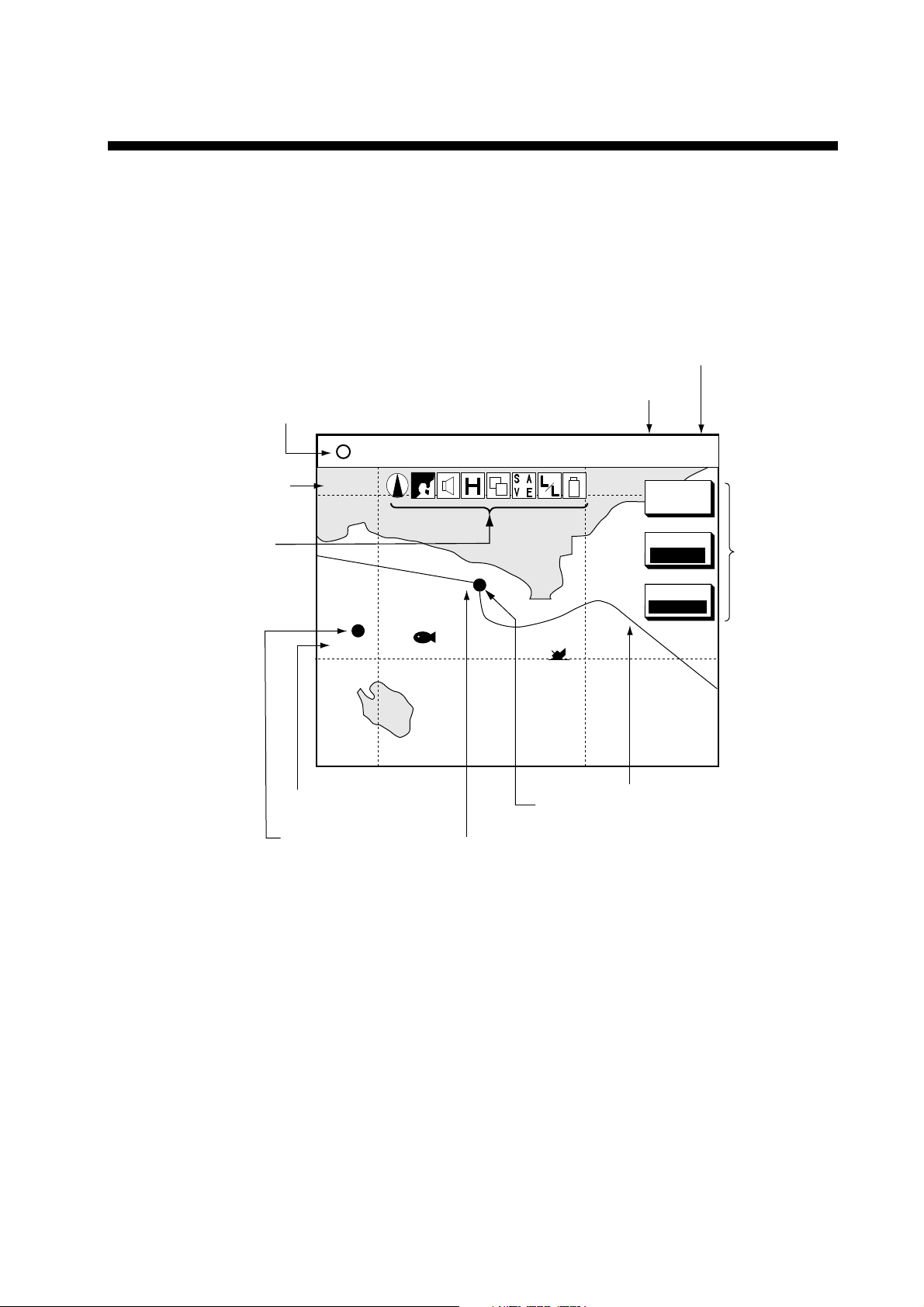
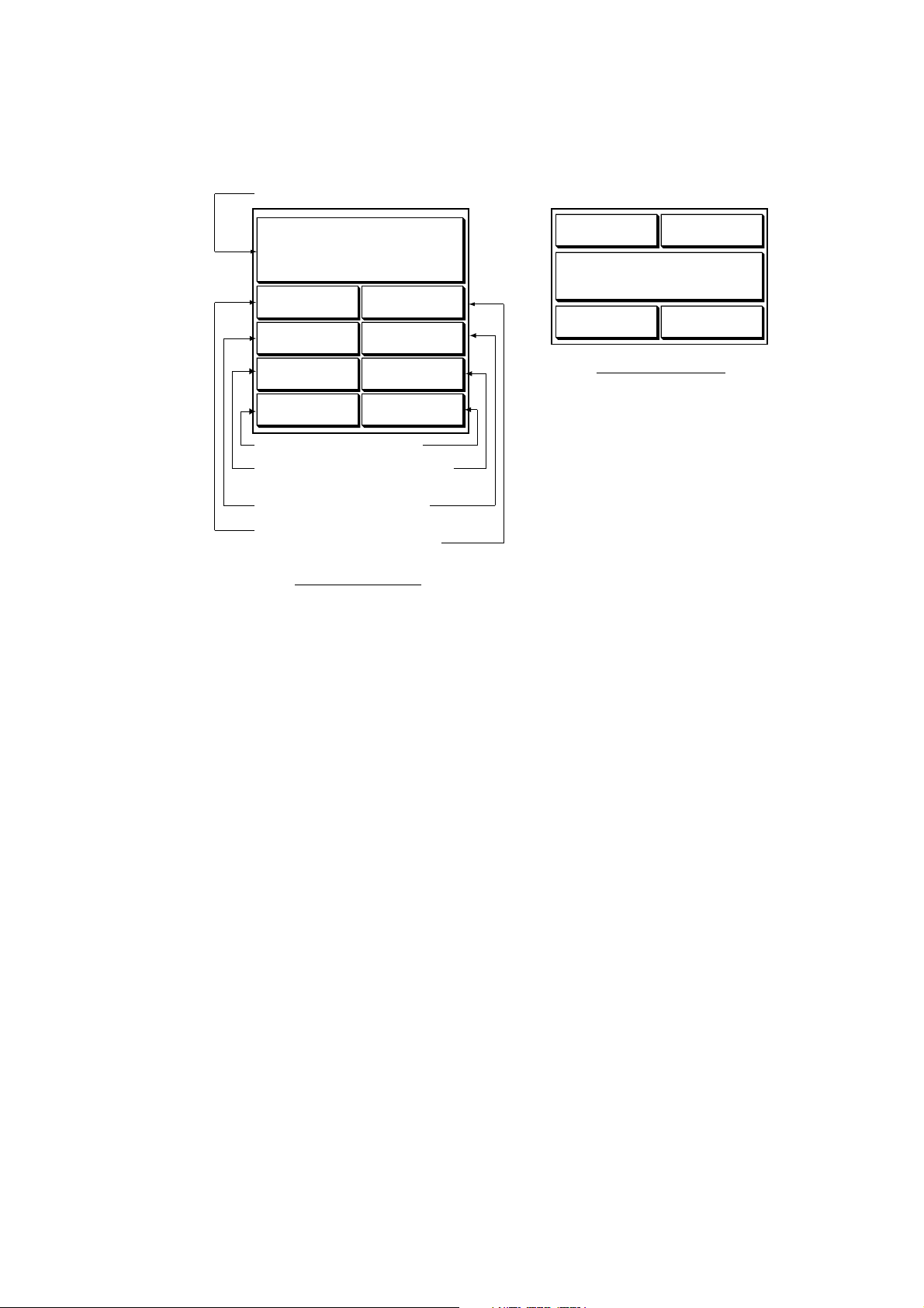
3.1.1 Normal plotter display
You may show the plotter display over the entire screen, in t he overlay screen
(MODEL-1700 series only) with the radar display, or in a combination screen.
Presentation mode
Nav data window
(Data changes with NAV soft
key setting and cursor
status. For details see next page.)
34° 22. 3456'N 359.9° TRIP NU
080° 22. 3456'E
Scale
1024 nm
Trip distance
19.9 kt 99.9 nm
(North-up)
MARK
ENTRY
Icon (from left)
North Marker
Chart
Alarm
Battery
Track Hold
Chart Offset
Save
L/L Offset
Battery
(See icon
table on
page A-3
for details.)
002WP
Waypoint name
Waypoint mark
FISH
BRIDGE
Own ship
marker
Course bar
Normal plotter display
Track
MODE
NTH-UP
NAV
POS
Functions for
soft keys
3-1
3. PLOTTER OPERATIO N
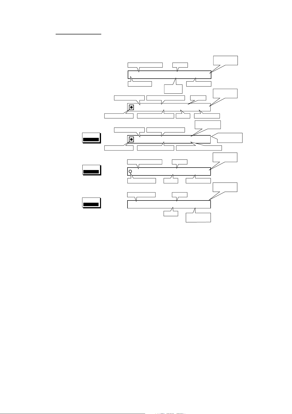
Nav data window
The data show in the nav data window depends on the status of the NAV soft key
and the cursor.
Position selected
with cursor
Waypoint selected
with cursor
NAV
WAYPT
soft key
NAV
POS
soft key
NAV
S/C
soft key
CourseLatitude, Longitude
34°24. 3456'N 359. 9°
+
124°24. 3456'W 59.9nm 99. 9nm
Cursor Mark
001WPT
Bearing to WaypointWaypoint Name
001WPT
34°24. 3456'N 359. 9°
124°24. 3456'W 19. 9kt 99. 9nm
Own Ship Mark Speed Trip Distance
CSE
359. 9° 359. 9° 79. 9°F NU
SPD
19. 9kt 99. 9nm 345 ft
Range to
Cursor
359. 9° 359. 9°
59. 9nm 59. 9kt 99. 9nm
359. 9°
19. 9nm
BRG
RNG
Range
TTG
ETA
CourseLatitude, Longitude
BearingCourse, Speed
TRIP
NU
Trip Distance
CourseBearing to WaypointWaypoint Name
TRIP
NU
SpeedRange to WaypointWaypoint Mark Trip Distance
Time-to-Go
to Destination
4d02h2h23mNU
1st 13:45
Estimated Time of ArrivalRange to WaypointWaypoint Mark
TRIP
NU
TMP
DPT
Water Temp.,
Depth
Presentation
Mode
Presentation
Mode
Presentation
Mode
Presentation
Mode
Presentation
Mode
NAV soft key status and nav data window
3-2

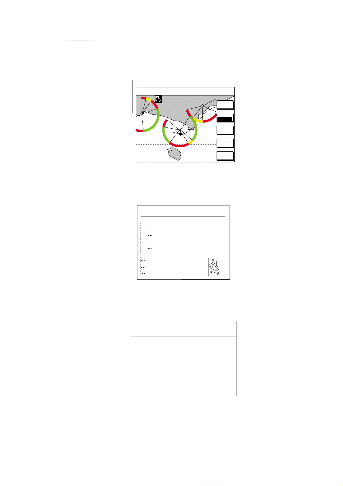
3.1.2 Compass display
The compass display, displayed at the bottom half of the screen in the
plotter/compass combination display, provides steering information. The
compass rose shows two arrows: the solid triangle shows own ship’s course
(heading) and the hollow inverted triangle shows the bearing to destination
waypoint. When own ship’s course is changed, the hollo w inverted t r iangle
moves with course change. Ship’s course and waypoint direction are updated
every second and other information is updated ever y 15 seco nds.
The water temperature and depth graphs shows latest 10 minutes of temperature
and depth data. The range of the depth graph is 50 feet and it is automatically
adjusted with depth.
3. PLOTTER OPERATIO N
Speed
Time-to-go
to destination
Depth
graph*
* = Requires appropriate
sensor
TTG
TO W a ypoint
003WPT
9h59m
Waypoint
bearing
350
400
Range to waypoint
RANGE
SOG
10.0
ETA
km/h STW
23th23:59
99.9km
10.0
BEARINGDEPTH TEMP
359.9°382.9ft 59.9°F
N
E
w
CSE
359.9
Ship's course
Bearing scale
XTE monitor
(Amount and
distance to
steer to return
to course)
km/h
Estimated time of
arrival at destination
80
Water
temperature
graph*
60
Compass display
3-3
3. PLOTTER OPERATIO N
Reading the XTE monitor
The XTE monitor, located below the compass rose, shows the direction you are
off course. In the example the monitor shows, by the solid triangle, that the vessel
is off course to the port side. Steer the vessel so the triangle keeps at the center
of the monitor scale.
Soft keys
EDIT XT-LMT: Sets the range for XTE monitor scale. See the procedure below
for how to set.
RESET XTE: Displayed when destination is set, and enables you to restart
navigation. When the key is pressed the following message is displayed.
RESTART NAVGATION TO
CURRENT WAYPOINT.
ARE YOU SURE?
YES ... PUSH ENTER KNOB
NO ... PUSH CLEAR KEY
COMPASS CNTRL: Switches control between the compass display and other
display, in a combination display.
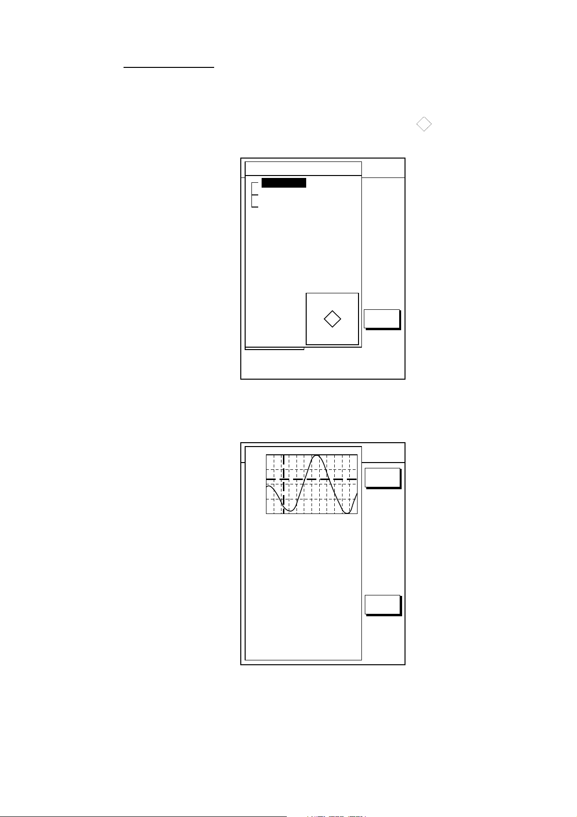
Setting the range for the XTE monitor
1. With the highway display shown, press the EDIT XT-LMT soft key to display
the following window.
XTE LIMIT
0 .1nm
DEFAULT: 0.1 nm (km, sm)
XTE range setting window
2. Use the cursor pad to select digit to change.
3. Use the [ENTER] knob to set.
4. Repeat steps 2 and 3.
5. Press the [ENTER] knob to set, or press the CANCEL soft key to cancel.
3-4
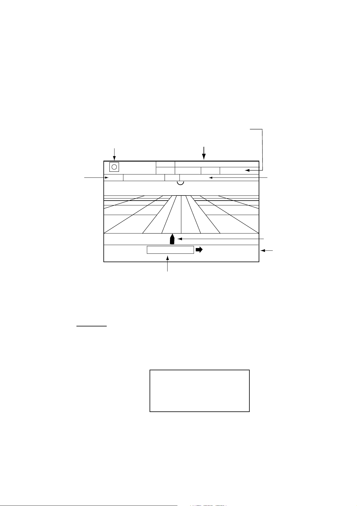
3.1.3 Highway display
The highway display, displayed at the lower half of the screen in the
plotter/highway combination displa y, provides a graphic presentation of ship’s
track along intended course. It is useful for monitoring ship’s pro gress t o a
waypoint. The own ship marker shows own ship’s movement and direction. The
XTE monitor to show the direction and amount your vessel is off course. The
arrow shows the direction to steer and the numeric the amount you are off course.
Using the figure below as an example, you would steer starboard 0.009 nm to
return to course.
3. PLOTTER OPERATIO N
Speed
Time-to-go
to destination
Note that all digits may be cleared by pressing the [CLEAR] key.
TO Waypoint
WPT001
0d9h59m
TTG
0.9 nm
Range to waypoint
99.9nm
RANG
SOG
10.0
km/h
STW
25th22:39
ETA
WPT001
0.009nm
XTE monitor
Highway display
10.0
km/h
0.9 nm
Estimated time of
arrival at destination
Own ship
XTE range
Soft keys
EDIT XT-LMT: Sets the range for XTE monitor scale. See the procedure on the
previous page for how to set.
RESET XTE: Displayed when destination is set, and enables you to restart
navigation. When the key is pressed the following message is displayed.
RESTART NAVGATION TO
CURRENT WAYPOINT.
ARE YOU SURE?
YES ... PUSH ENTER KNOB
NO ... PUSH CLEAR KEY
COMPASS CNTRL: Switches control between the compass display and other
display, in a combination display.
3-5
3. PLOTTER OPERATIO N
3.1.4 Nav data display
The nav data display provides comprehensive navigatio n data. It can be
displayed on the entire screen or in a combination display.
Position
POS
34° 34. 5678' N
120° 34. 5678'
SPEED
99.9
DEPTH
1200
RANG
99.9
LOG TRIP
99.9
km/s
f t
nm
nm
W
COURSE
359.9˚
TEMP.
109.9
BEARING
359.9˚
DATE 2000
24. SEP
T
˚F
km/s
COURSE
359.9˚
SPEED
99.9
POS 34° 34. 5678' N
120° 34. 5678'
f t
TEMP.
109.9
DEPTH
1200
Half-screen display
T
W
˚F
Trip distance
Range to
waypoint
Depth
Speed
Full-screen display
Date
Bearing to
waypoint
Water
temperature
Course
Full-screen nav data display
3-6
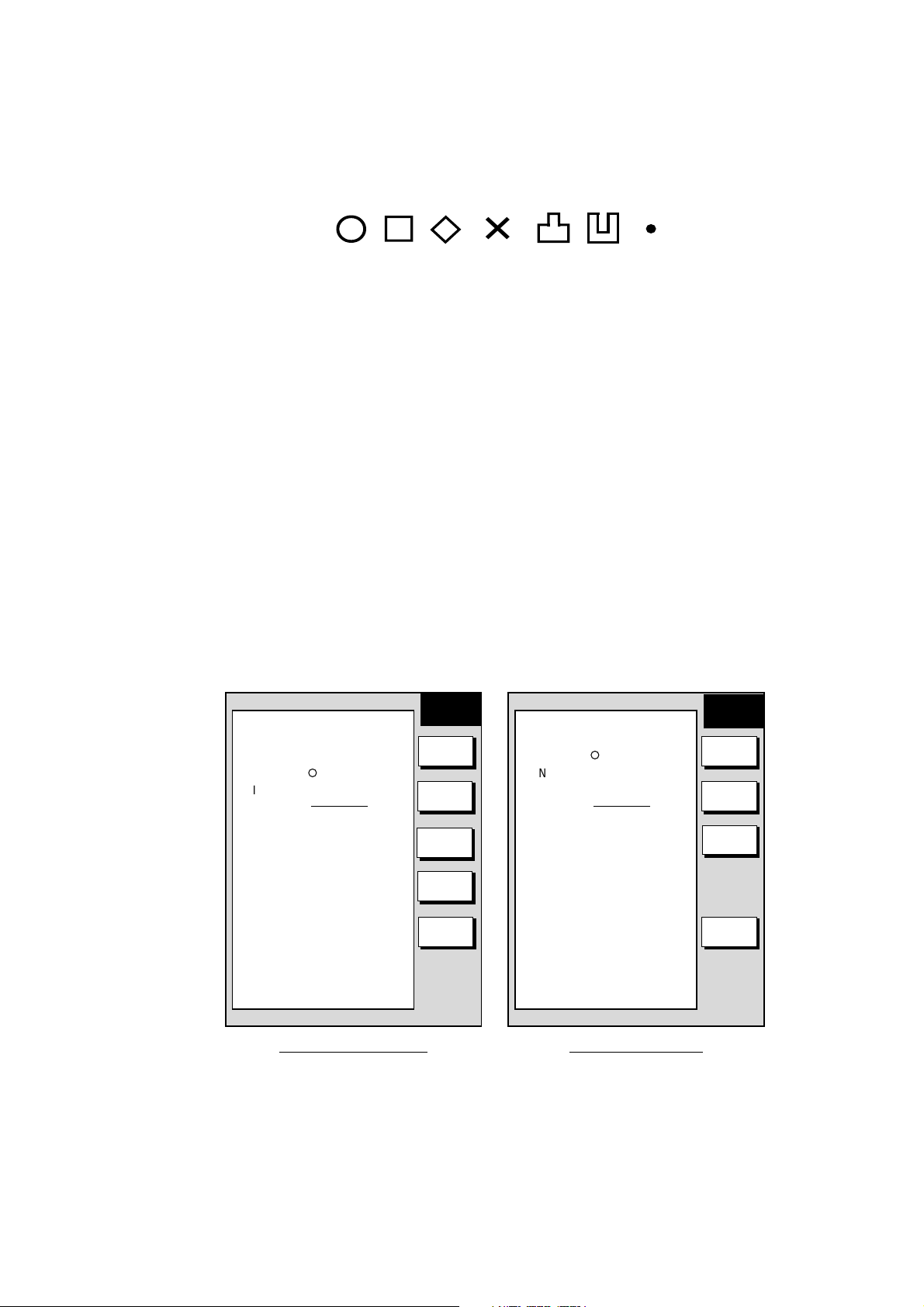
3.2 Selecting a Presentation Mode
Three types of display presentations are provided for the plotter display: north-up,
course-up and auto course-up. To change the presentation mode, use the MODE
soft key. Each press of the key changes the presentation mode and presentation
mode indication cyclically in the sequence of North-up, Course-up and Auto
course-up.
3.2.1 North-up
Press the MODE soft key to show “AC-UP.” North (zero degree) is at the top of
the display and own ship is at the center of the screen. Own ship marker is a filled
circle. This mode is useful for long-range navigation.
34° 22. 3456'N 359.9° TRIP NU
080° 22. 3456'E
1024 nm
19.9 kt 99.9 nm
3. PLOTTER OPERATIO N
MARK
ENTRY
MODE
NTH UP
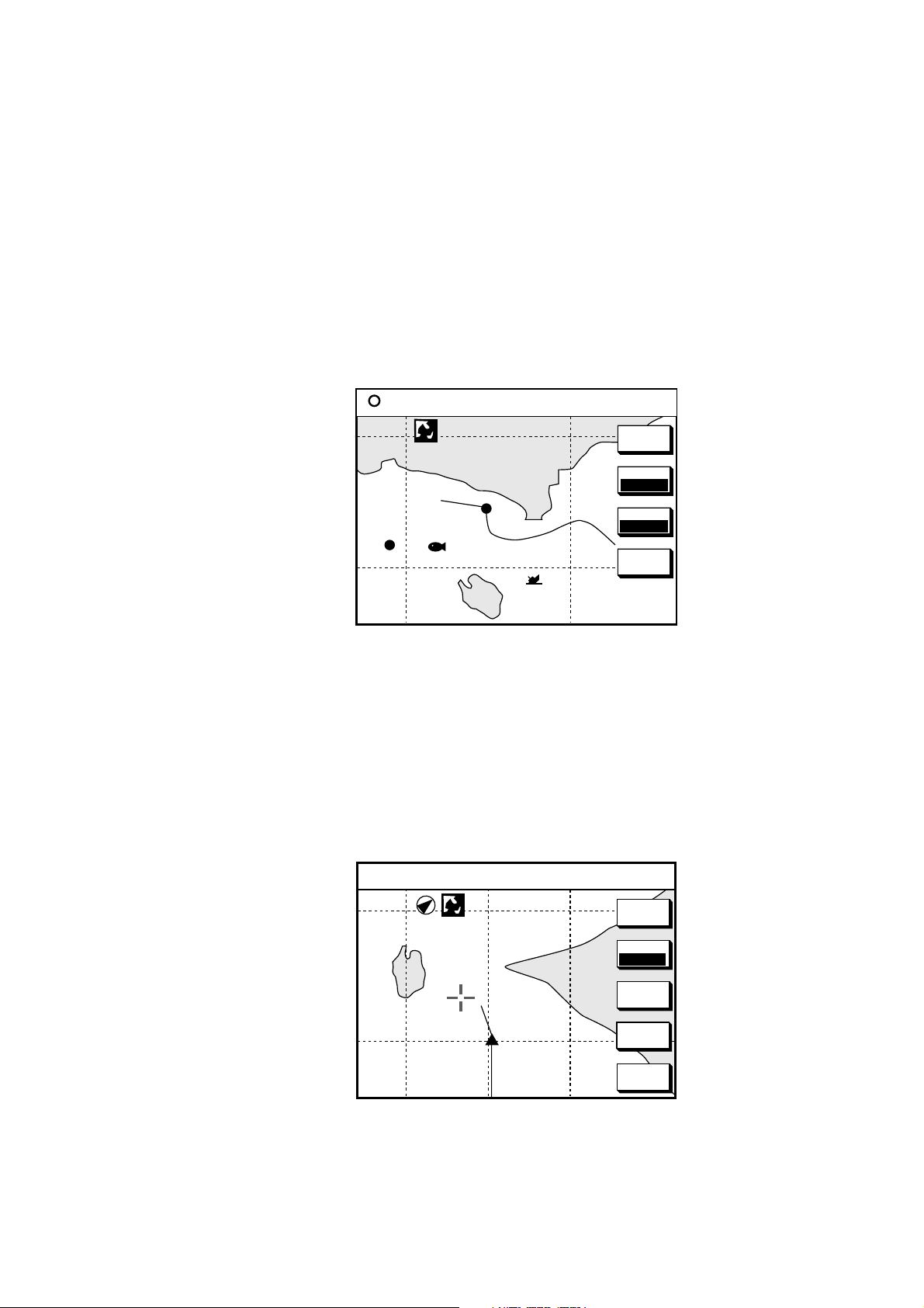
3.2.2 Course-up
Press the MODE soft key to show the indication NTH-UP. When destination is set
it is at the top of the screen, the north mark appears at the upper left side of the
screen and points to north. A filled triangle marks own ship’s position.
When destination is not set, the course or heading is upward on the screen at the
moment the course-up mode is selected.
WP-002
FISH
BRIDGE
Plotter display, north-up mode
34° 22. 3456'N 272.4° TRIP CU
+
080° 22. 3456'E
15.9 nm 99.9 nm
1024 nm
NAV
POS
D.BOX
OFF
MARK
ENTRY
MODE
CSE UP
CENTER
GO TO
CURSOR
D.BO X
OFF
Plotter display, course-up mode, cursor on
3-7
3. PLOTTER OPERATIO N
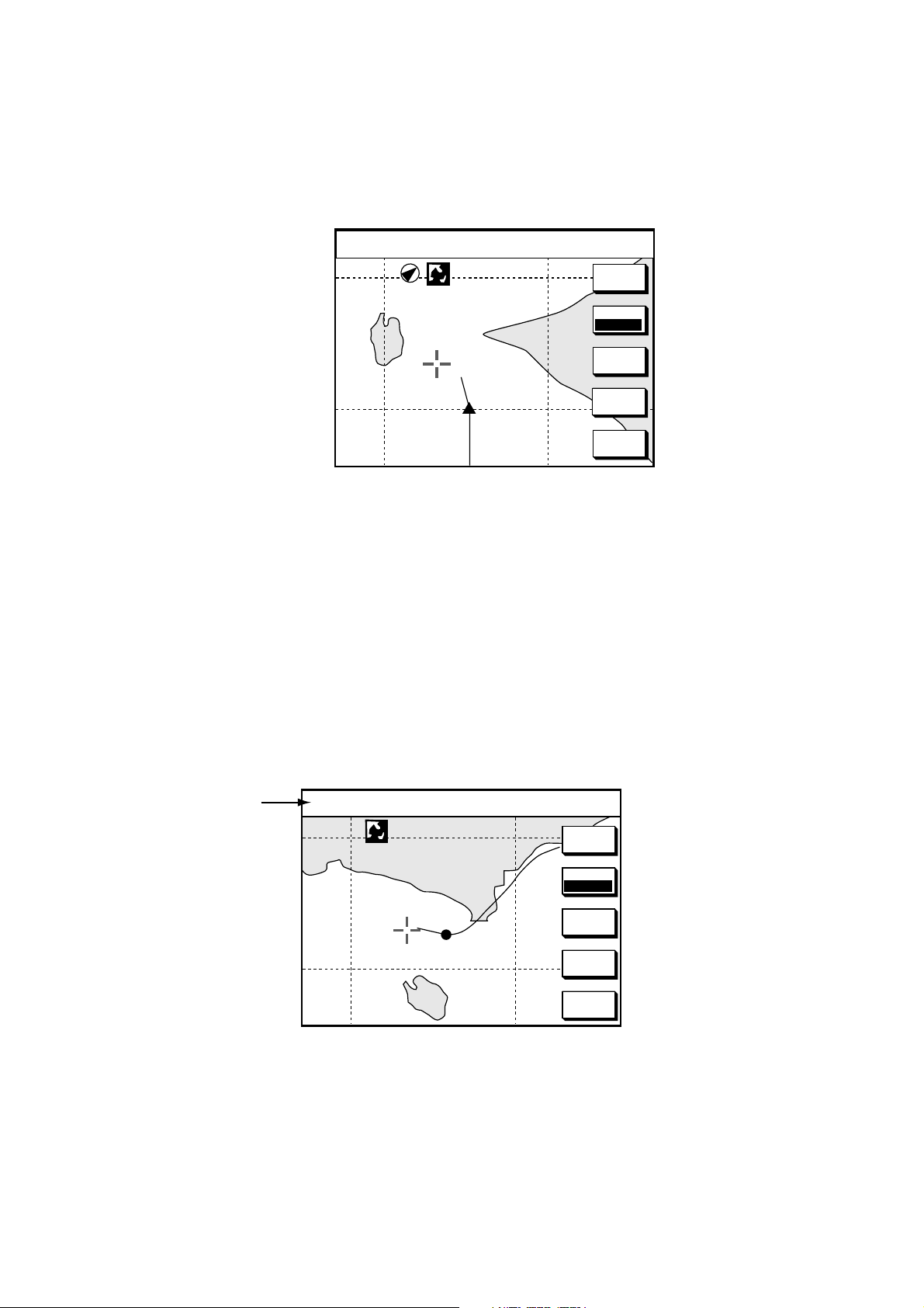
3.2.3 Auto course-up
Press the MODE soft key to show the indication CSE-UP. T he course or heading
is at the top of screen at the moment the course-up m ode is selected. When own
ship is off its intended course by 22.5
perpendicular.
° or more, it is automatically brought back to
34° 22. 3456'N 272.4° TRIP ACU
+
080° 22. 3456'E
1024 nm
15.9 nm 99.9 nm
MARK
ENTRY
MODE
AUT CU
CENTER
GO TO
CURSOR
D.BOX
Plotter display, auto course-up mode
OFF
3.3 Cursor
3.3.1 Turning on the cursor, shifting the cursor
Press the cursor pad to turn the cursor on, and the cursor appears at the own
ship’s position. Operate the cursor pad to shift the cursor. The cursor moves in
the direction of the arrow or diagonal pressed on the cursor pad.
Cursor position is displayed in latitude and longitude or Loran or Decca TDs
(depending on menu setting) at the t op of t he plotter display when the cursor is
on.
34° 22. 3456'N 272.4° TRIP NU
Cursor data
+
080° 22. 3456'E
1024 nm
15.9 nm 99.9 nm
MARK
ENTRY
MODE
NTH UP
CENTER
GO TO
CURSOR
D.BOX
OFF
Cursor data
3.3.2 Turning off the cursor, returning own ship marker to screen
center
The CENTER soft key turns off the cursor and returns own ship marker to screen
center.
3-8
3.4 Shifting the Display
The display can be shifted on the plotter display as below.
1. Press the cursor pad to display the cursor.
2. Locate the cursor at a screen edge and press and hold down the cursor pad.
The screen shifts in the direction opposite of cursor location.
3.5 Selecting Chart Scale/Range
Chart scale (range) may be selected with the [-] or [+] key. The [-] key expands
the chart range; the [+] key shrinks it.
Note: When the display is expanded or shrunk beyond the range of t he chart
card in use NO CHART appears, along with the appropriate chart icon. See
the table below for details.
3. PLOTTER OPERATIO N
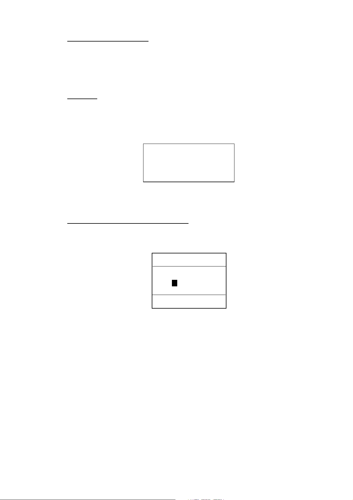
3.6 Chart Cards
3.6.1 Chart card overview
Three types of chart cards can be used: FURUNO, Nav-Charts ™ (NAVIONICS)
and C-MAP.
When you insert a suitable mini chart card in the slot and your boat is near land, a
chart appears. If a wrong card is inserted or a wrong chart scale is selected, the
land will be hollow. Insert the proper card and select a suitable chart scale. Chart
icons appear to help you select a suitable chart scale. The table below shows the
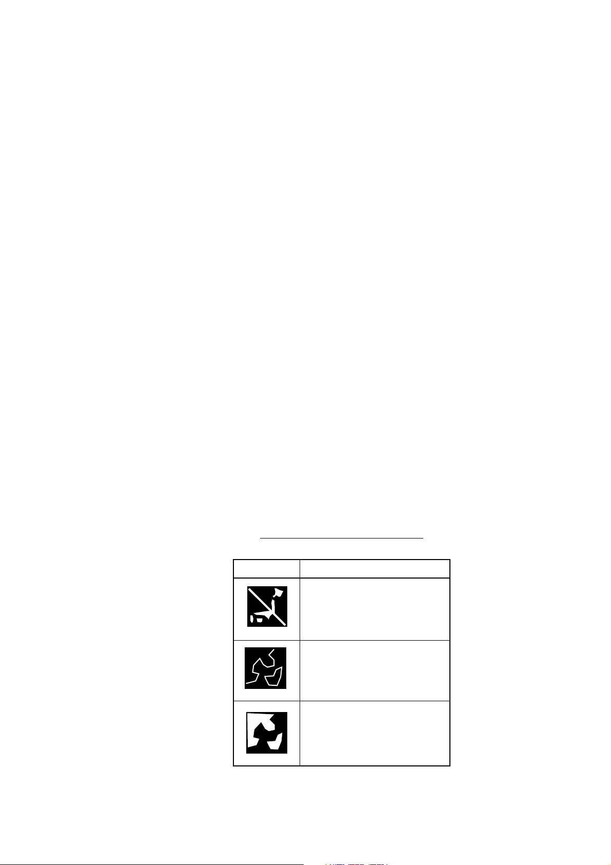
chart icons and their meanings.
Icon Meaning
Chart icons and their meanings
Proper card is not inserted or
chart scale is too small. Press
the soft key ZOOM IN to
adjust chart scale.
Chart scale is too large. Press
the soft key ZOOM OUT to
adjust chart scale.
Suitable chart scale is
selected.
3-9
3. PLOTTER OPERATIO N
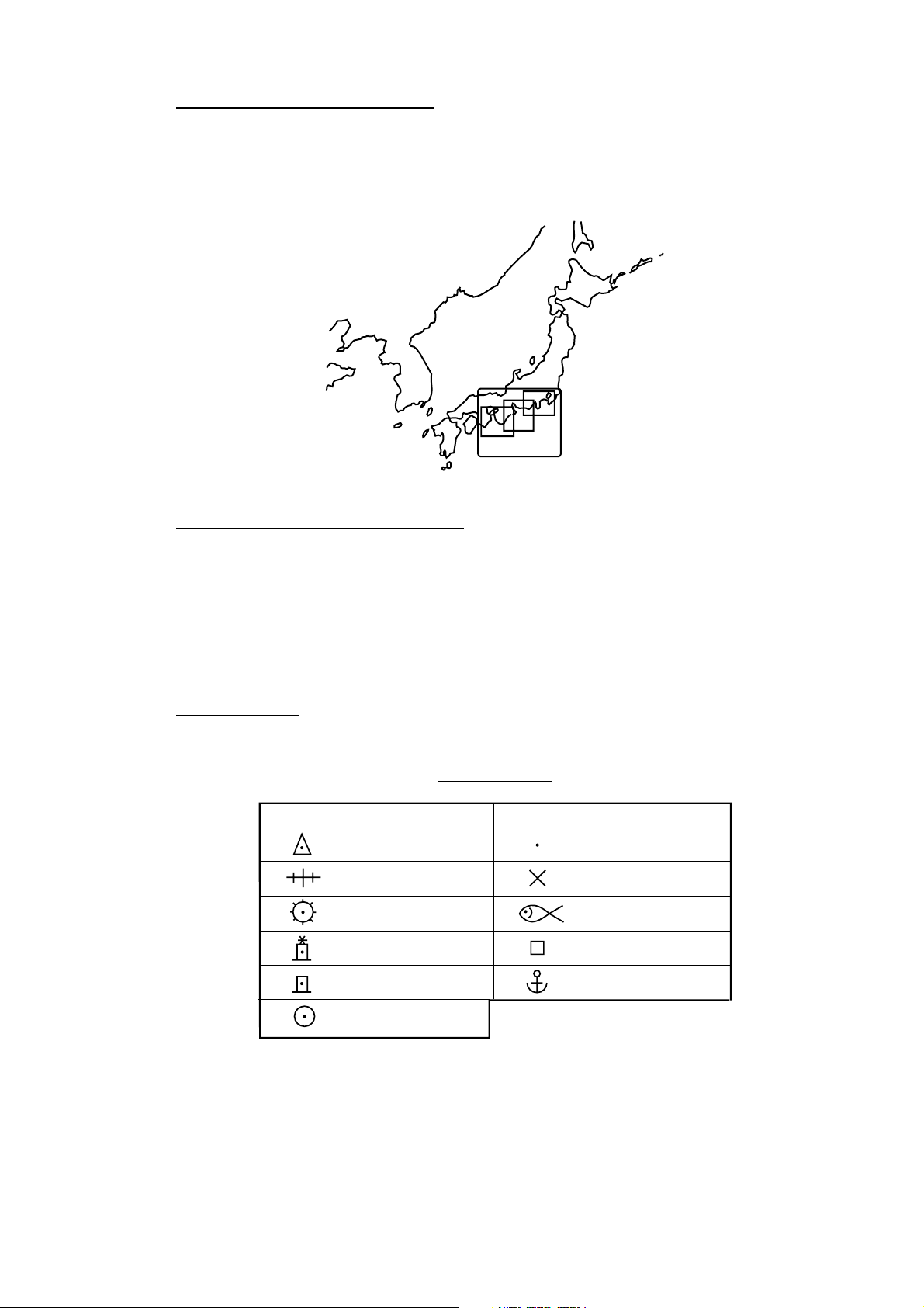
Indices and chart enlarg ement
When the [-] key is operated, you will see several fram es appear on the chart.
These frames are called indices and they show you what parts of the chart can be
enlarged in the current picture range. The areas circumscribed with smaller
frames can be enlarged, but the area enclosed by the largest frame cannot.
Sample chart (Japan and South Korea) showing indices
When a chart cannot be displayed
A chart will not be displayed in the following conditions:
• When the chart scale is too large or too small.
• When scrolling the chart outside the indices.
• When this happens, select proper chart scale.
3.6.3 FURUNO, Nav-Charts™
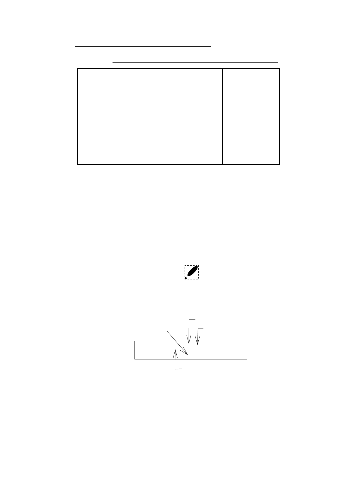
Chart symbols
The table below shows FURUNO mini chart symbols and their meanings.
Symbol Description
Summit
Wreck
Lighthouse
Lighted Buoy
Chart symbols
Symbol Description
Position of Sounding
Obstruction
Fishing Reef
Platform
3-10
Buoy
Radio Station
Anchorage
Comparison of FURUNO and Nav-Charts™
Comparison of FURUNO and Nav-Charts™ chart cards
Item FURUNO Nav-Charts™
Dot scrolling capability YES YES
Course-up display YES YES
Lighthouse data YES *3 YES
Zoom at cursor position YES *1
3. PLOTTER OPERATIO N
Range at Equator 0.125, 0.5, 1, 2…2048
nm
Chart offset YES YES
Centering YES *2
Same as left
*1 Nav-Charts™ chart may not center the cursor perfectly.
*2 Nav-Charts
™ chart may not center own ship's position perfectly.
*3 Newly designed chart cards containing lighthouse data. Chart cards for North
America area are completed, and others are in production.
*4 Nav-Charts
™ is the registered trademark of NAVIONICS INC.
Data for aids to navigation data
Selected FURUNO and Nav-Charts™ charts can show buoy and lighthouse data.
Simply place the cursor on the lighthouse or buoy mark.
Place the cursor on
a lighthouse or buoy mark.
Lighthouse mark
Range and bearing
from own ship
Period (ex.: 6 seconds)
Visibility in nautical
mile (ex.: 12 miles)
NAVAID: /FL 6S 12M
FROM OS 52.38nm 48.0°
FL : Flashing
F : Fixed light
F FL : Fixed and Flashing light
MO : Morse code light
Oc : Occulting light
Example of buoy, lighthouse data
3-11
3. PLOTTER OPERATIO N
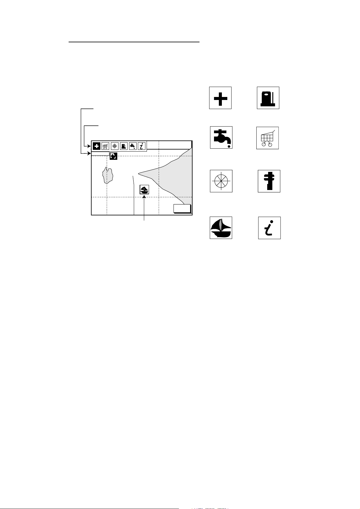
Port service icons (Nav-Charts™ cards)
Selected Nav-Charts™ mini chart cards show by icons services available at ports.
Use the cursor pad to place the cursor on the sailboat icon (denotes a port or
harbor), and then push the [ENTER] knob. The services available appear at the
top of the display.
Detailed information of service
selected
List of services
at the port selected
34° 22. 3456'N 359.9° TRIP NU
080° 22. 3456'E
FIRST AID
19.9 kt 99.9 nm
1024 nm
Sailboat mark (Port)
CANCEL
Emergency
medical service
Water
supply station
Customer
service station
Port
Plotter display showing Nav-Charts™ port service display
Fueling station
Traveler's
service station
Marine
equipment service
Information center
3-12
3.6.4 C-MAP cards
Cursor and data display
Besides its fundamental functions of providing position data, t he cursor can also
show caution area, depth area, source of data, et c. Furt her, you can display
information about an icon by placing the cursor on it .
1. Press the cursor pad to turn the cursor on.
2. Use the cursor pad to place the cursor on the position desired.
3. Push the [ENTER] knob to open the Objects window.
34 24. 3456 N 359.9 NU
+
OBJECTS
124 24. 3456 W 59.9kt 024nm
Tide height
Cartographic area
Source of data
3. PLOTTER OPERATIO N
T
RETURN
Objects window
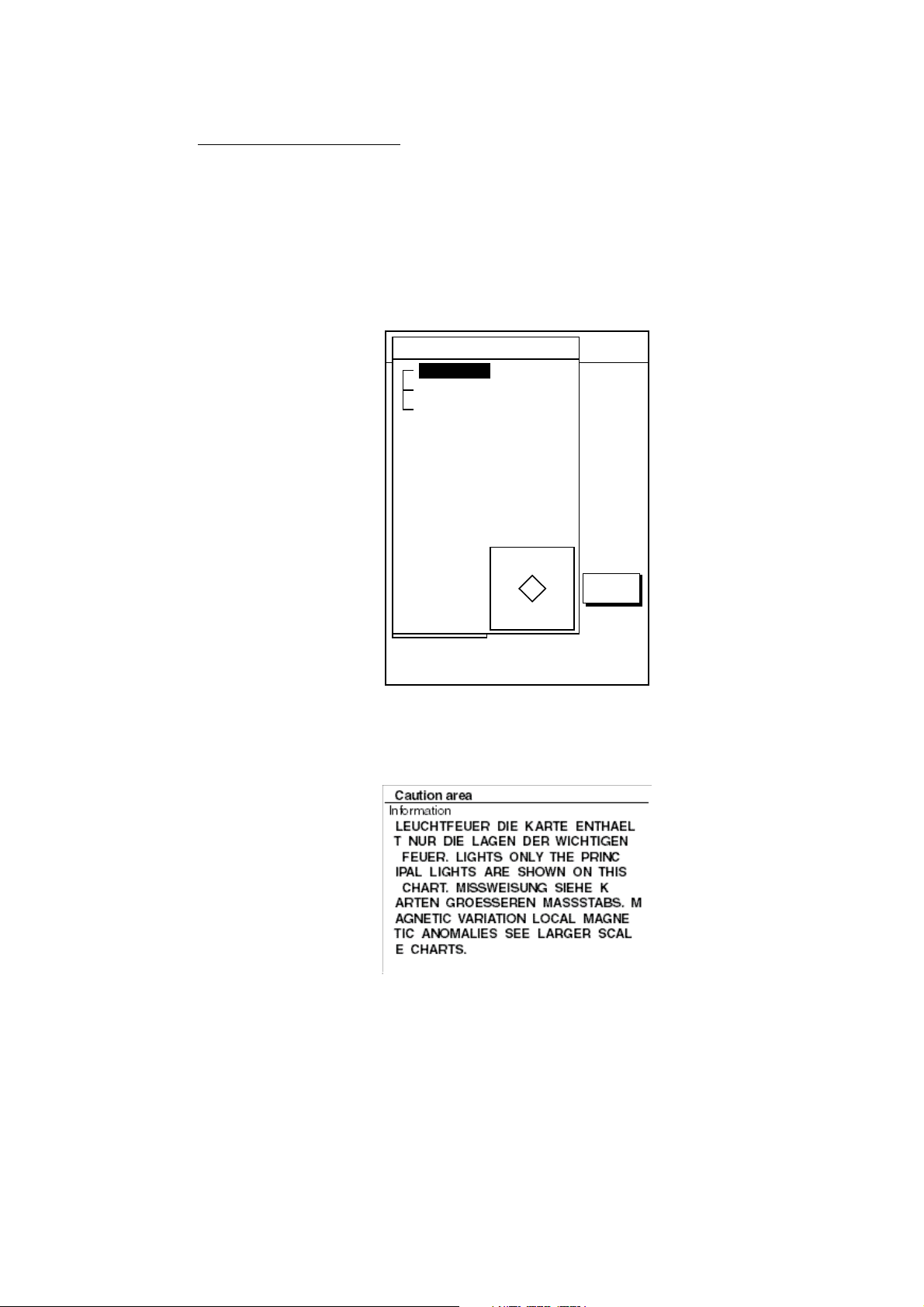
4. Select the item desired.
5. Push the [ENTER] knob to display details for object selected.
Example of caution area window
6. Press the RETURN soft key to close the window.
7. Repeat step 4 to 6 to select other item.
8. Press the RETURN soft key to close the Objects window and the [MENU] key
to close the menu.
3-13
3. PLOTTER OPERATIO N
Icon data
You may place the cursor on any icon to find information about the selected icon.
1. For example, place the cursor on a lighthouse icon.
Place the cursor on a lighthouse icon.
34° 22. 3456'N 359.9° TRIP NU
+
080° 22. 3456'E
1024 nm
19.9 kt 99.9 nm
MARK
ENTRY
MODE
NTH UP
CENTER
GO TO
CURSOR
D.BOX
OFF
Lighthouse icon
2. Push the [ENTER] knob to show data. For example, t he following window
appears for lighthouse.
Objects
Navigation mark, fixed
Extended navigational aid, ge
Light
Light
Light
Light
Depth contour
Land area
Source of data
Object windows
3. Select the item desired.
4. Push the [ENTER] knob to display detailed inf ormation.
Navigation mark, fixed
Light.
Color
white
Height
7. 00 Meters
Light characteristic
occulting
XXXXXXXX
XXXXXXXX
3-14
Sample lighthouse data
5. Press the RETURN soft key to close the Objects window and the [MENU] key
to close the menu.
3. PLOTTER OPERATIO N
Tidal Information
The C-MAP NT-FP chart card provides for calculation of the tide heights for any
date. Additionally it displays the times of sunrise and sunset.
T
1. Press the cursor pad to place the cursor on a Tide icon (
).
2. Push the [ENTER] knob to open the Objects window.
34 24. 3456 N 359.9 NU
+
OBJECTS
124 24. 3456 W 59.9kt 024nm
Tide height
Cartographic area
Source of data
T
RETURN
Objects window
3. Select Tide height.
4. Push the [ENTER] knob to open the TIDE window.
34 24. 3456 N 359.9 NU
+
0.86
124 24. 3456 W 59.9kt 024nm
0.74
0.61
0.48
0.35
04812162024
Time: 04:35
Height: 0.45ft
Draught: 0.65ft
01/07/30 +13:30
43° 32.860N
010° 18.022E
DATE
Port info
LIVORNO (LEGHORN)
High Water(max)
Low Water(min)
Sunrise
07:52L
0.86ft(13:30 L)
0.35ft(21:00 L)
Sunset
16:53 L
Tide window
RETURN
3-15
3. PLOTTER OPERATIO N
5. Press the DATE soft key to open the DATE window.
6. Place the cursor where desired and then rotate the [E NTER] knob to enter a
appropriate date.
7. Push the [ENTER] knob to show the tidal graph for entered date.
8. Locate the vertical cursor on the time desired. Time and height are shown to
the left of the graph.
9. Shift the level cursor. Draught is shown to the left of the graph.
10.Press the RETURN soft key to close the TIDE window.
11.Press the [MENU] key to close the menu.
DA TE
DD/MM/YYYY
01 / 01 / 2000
Date window
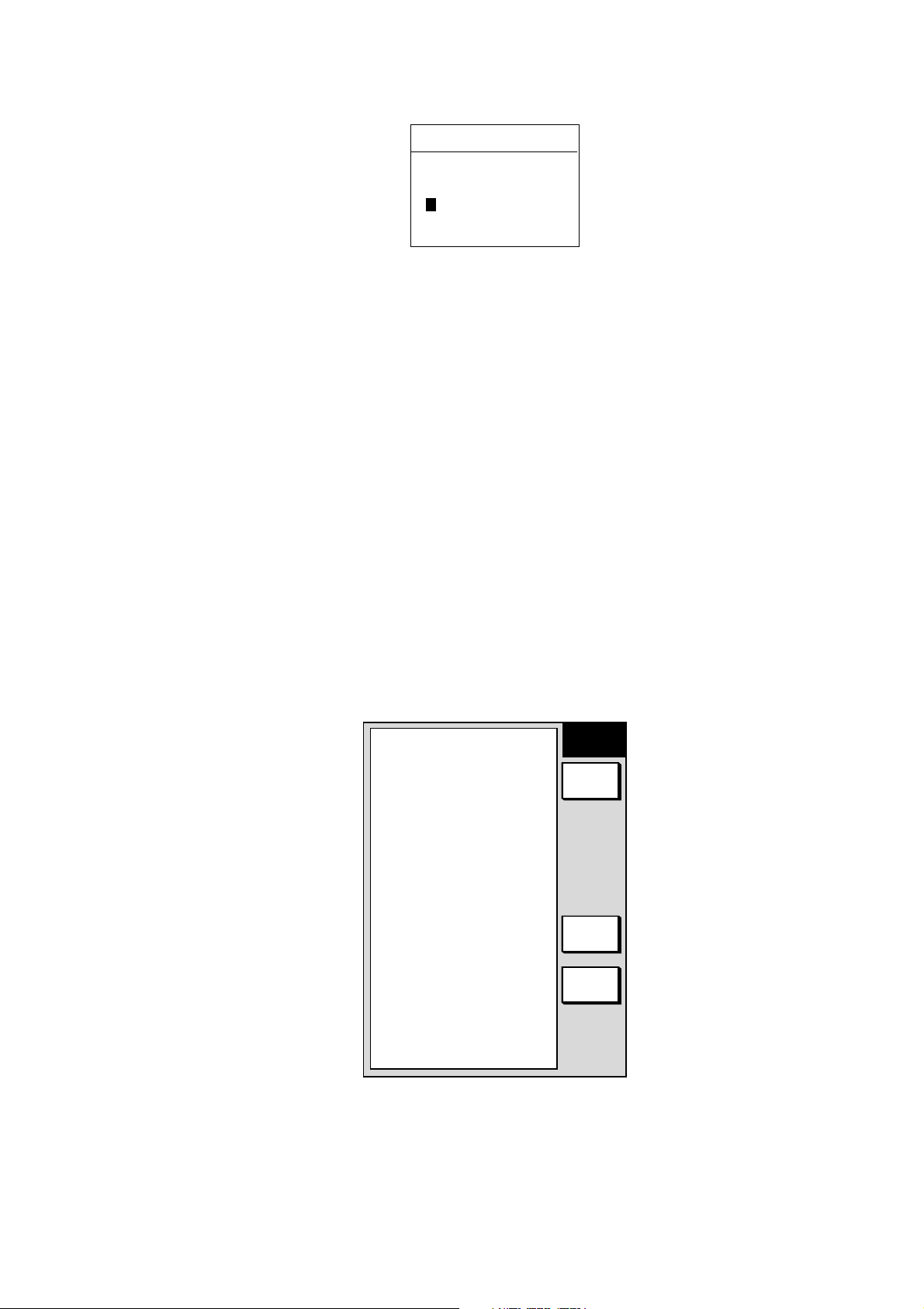
3.7 Resetting Trip Distance
Trip distance is shown on the navigation data display. You can reset the trip
distance to zero as follows.
1. Press the [MENU] key.
2. Press the SYSTEM CONFIGURATION and GENERAL SETUP soft keys in
that order to show the general setup menu.
KEY BEEP
ON
LANGUAGE
▲
RANGE/SPEED UNIT
TEMP UNIT
DEPTH UNIT
TEMP SOURCE
DEPTH SOURCE
RESET TRIP LOG
ENGLISH
nm, kt
°C
ft
NMEA
NMEA
NO
GENERAL
SETUP 1
EDIT
NEXT
PAGE
RETURN
3-16
General setup menu, page 1

3. Select RESET TRIP LOG and press the EDIT soft key.
4. Select YES.
5. Press the RETURN soft key.
6. Press the [MENU] key to close the menu.
3.8 Working with Track
Your ship’s track is plotted on the screen using navigation data fed from a GPS
receiver. This section shows you what you can do with track, from turning it on or
off to changing its plotting interval.
3.8.1 Displaying track
Own ship track
1. Press the [MENU] key followed by CHART SETUP and TRACK & MARK
CONTROL soft keys to open the track control menu.
▲
TRACK DISPLAY
ON
TRACK COLOR
RED
TARGET TRACK DISPLAY
ON
TARGET TRACK COLOR
WHITE
PLOT
TIME
TIME INTERVAL
10m00sec
DIST INTERVAL
0.1nm
TRACK MEMORY(MARK)
2000PTS(6000PTS)
TRACK
CONTROL
EDIT
TRACK
HALT
ERASE
T & M
MARK
SETUP
RETURN
3. PLOTTER OPERATIO N
▲
TRACK DISPLAY
ON
TARGET TRACK DISPLAY
ON
PLOT
TIME
TIME INTERVAL
10m00sec
DIST INTERVAL
0.1nm
TRACK MEMORY(MARK)
2000PTS(6000PTS)
TRACK
CONTROL
EDIT
TRACK
HALT
ERASE
T & M
MARK
SETUP
RETURN
OWN SHIP TRACK STATUS
TRACKING
TRACK 1234/2000
MARK 36/6000
MODEL-1700C series
OWN SHIP TRACK STATUS
TRACKING
TRACK 1234/2000
MARK 36/6000
MODEL-1700 series
Track & mark control menu
2. Select TRACK DISPLAY.
3. Press the EDIT soft key to show the display track window.
4. Select ON (default setting) or OFF as appropriate.
5. Press the RETURN soft key.
6. Press the [MENU] key to close the menu.
Note: The number of track and mark points used appears at the TRACK STATUS
window on the track control menu. Using the figure above as an example,
1234 points (max. 2000 points) and 36 marks (max. 5000 points)
respectively have been recorded.
3-17
3. PLOTTER OPERATIO N
Target track
Target track, NMEA format TTM data sentence or target data fed from an ARPA
board-equipped radar, may be turned on or off as desired. The default setting is
off.
1. Press the [MENU] key followed by CHART SETUP and TRACK & MARK
CONTROL soft keys to open the track control menu.
2. Select TARGET TRACK DISPLAY.
3. Press the EDIT soft key to show the target track display window.
4. Select ON or OFF (default setting) as appropriate.
5. Press the RETURN soft key followed by the [MENU] key to close the menu.
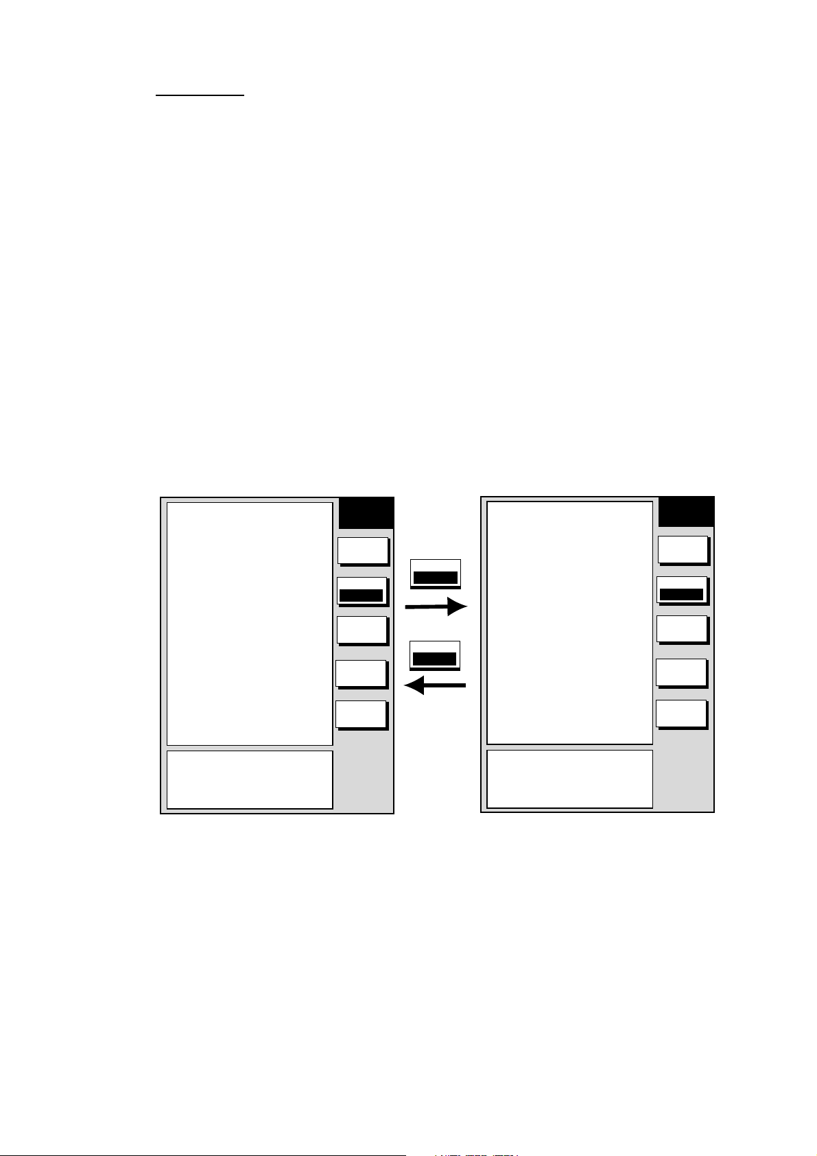
3.8.2 Stopping, restarting plotting of own ship track
When your boat is at anchor or returning to port you probably won’t need to
record its track. You can stop recording the track, to conserve the track memory,
as follows:
1. Press the [MENU] key followed by CHART SETUP and TRACK & MARK
CONTROL soft keys to open the track control menu.
▲
TRACK DISPLAY
ON
TRACK COLOR
RED
TARGET TRACK DISPLAY
ON
TARGET TRACK COLOR
WHITE
PLOT
TIME
TIME INTERVAL
10m00sec
DIST INTERVAL
0.1nm
TRACK MEMORY(MARK)
2000PTS(6000PTS)
OWN SHIP TRACK STATUS
TRACKING
TRACK 1234/2000
MARK 36/6000
TRACK
CONTROL
EDIT
TRACK
HALT
ERASE
T & M
MARK
SETUP
RETURN
TRACK
HALT
TRACK
RESUME
▲
TRACK DISPLAY
ON
TRACK COLOR
RED
TARGET TRACK DISPLAY
ON
TARGET TRACK COLOR
WHITE
PLOT
TIME
TIME INTERVAL
10m00sec
DIST INTERVAL
0.1nm
TRACK MEMORY(MARK)
2000PTS(6000PTS)
OWN SHIP TRACK STATUS
NOT TRACKING
TRACK 1234/2000
MARK 36/6000
TRACK
CONTROL
EDIT
TRACK
RESUME
ERASE
T & M
MARK
SETUP
RETURN
Track & mark control menu (MODEL-1700C series)
3-18
2. Press the TRACK HALT soft key. The indication “TRACKING” in the TRACK
STATUS window changes to “NOT TRACKING. ” Further t he icon “H” is
displayed at the top of the plotter display. To restart plotting the track, press
the TRACK RESUME soft key.
3. Press the RETURN soft key.
4. Press the [MENU] key to close the menu.
3. PLOTTER OPERATIO N
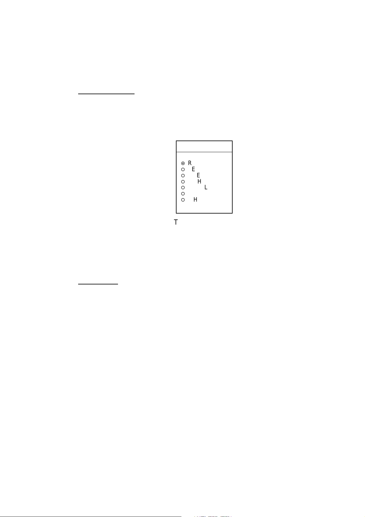
3.8.3 Changing track color (MODEL-1700C series only)
Track can be displayed in red, yellow, green, light-blue, purple, blue and white. It
can be useful to change track color on a regular basis to discriminat e between
previous day's track, past track, etc. The default own ship track color is red.
Own ship’s track
1. Press the [MENU] key followed by CHART SETUP and TRACK & MARK
CONTROL soft keys to open the track control menu.
2. Select TRACK COLOR.
3. Press the EDIT soft key to display the track color window.
TRACK COLOR
▲
¤
RED
¡
YELLOW
¡
GREEN
¡
LIGHT BLUE
¡
PURPLE
¡
BLUE
¡
WHITE
▼
Track color window
4. Select the color desired.
5. Press the ENTER soft key.
6. Press the RETURN soft key.
7. Press the [MENU] key to close the menu.
Target track
Like own ship’s track, target tracks can be displayed in red, yellow, green, lightblue, purple, blue and white (def ault setting).
1. Press the [MENU] key followed by CHART SETUP and TRACK & MARK
CONTROL soft keys to open the track control menu.
2. Select TARGET TRACK COLOR.
3. Press the EDIT soft key to display the track color window.
4. Select the color desired.
5. Press the ENTER soft key.
6. Press the RETURN soft key.
7. Press the [MENU] key to close the menu.
3-19
3. PLOTTER OPERATIO N
3.8.4 Track plotting method and i nterval for own ship track
In drawing the own ship track, first the ship’s position (fed from the blackbox GPS
unit or DGPS/GPS receiver) is stored into the unit’s memory at an interval of time
or distance. A shorter interval provides better reconstruction of the tr ack, but the
storage time of the track is reduced. When the track memory becomes full, the
oldest track is erased to make room for the latest.
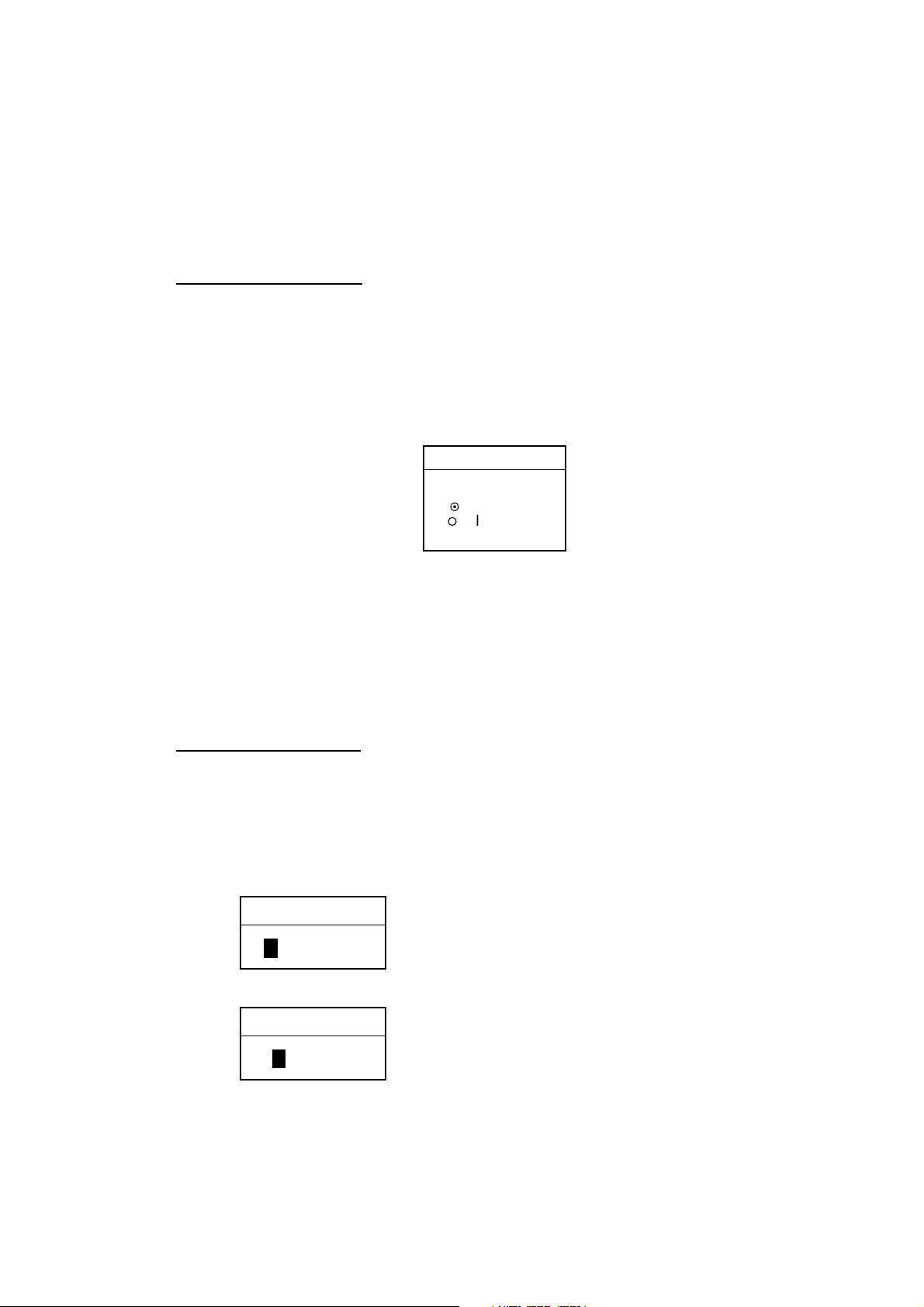
Track plotting method
Track may be plotted by time or distance interval and the default setting is “time.”
1. Press the [MENU] key followed by CHART SETUP and TRACK & MARK
CONTROL soft keys to open the track control m enu.
2. Select PLOT.
3. Press the EDIT soft key to display the plot window.
PLOT
▲
¤
TIME
¡
DISTANCE
▼
Plot window
4. Select TIME or DISTANCE as appropriate. Distance is useful for conserving
track memory, since no track is recorded when the boat is stationary.
5. Press the ENTER soft key.
6. Press the RETURN soft key.
7. Press the [MENU] key to close the menu.
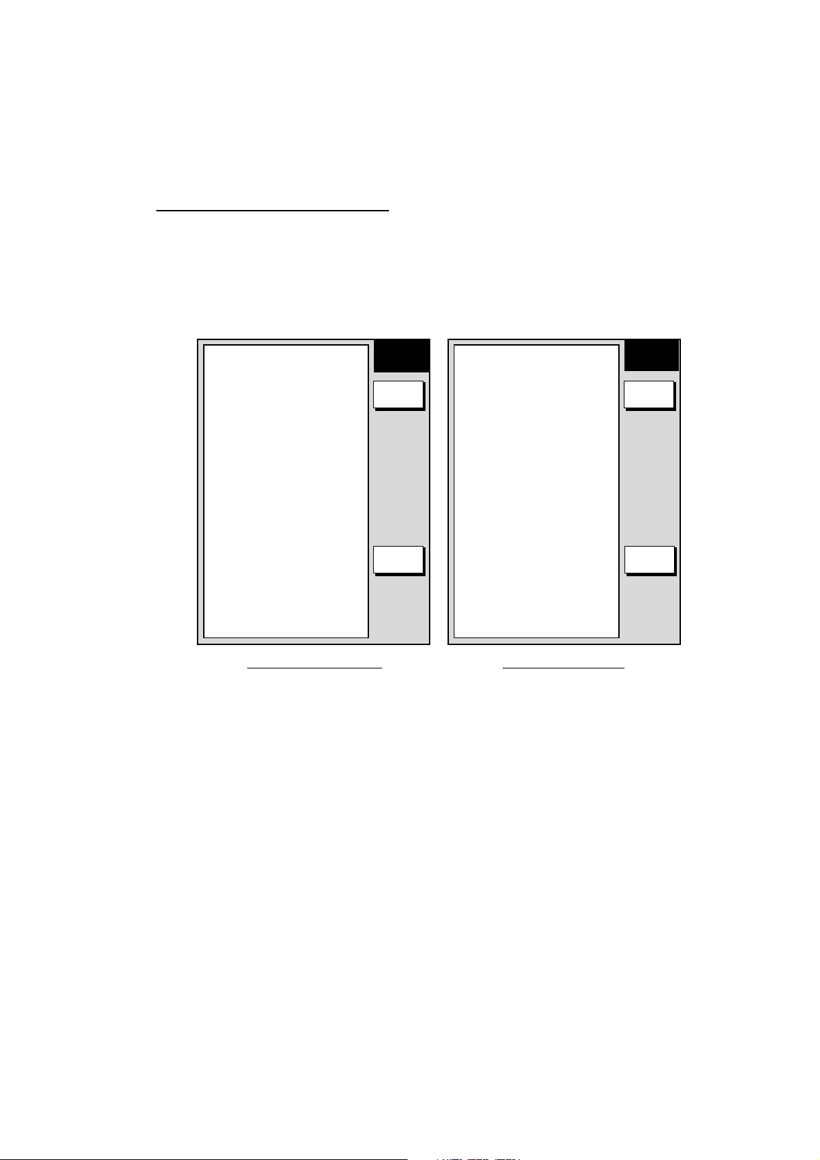
Track plotting interval
1. Press the [MENU] key followed by CHART SETUP and TRACK & MARK
CONTROL soft keys to open the track control m enu.
2. Select TIME INTERVAL or DIST INTERVAL as appropriate
3. Press the EDIT soft key to display the time or distance interval window,
whichever you selected at step 2.
TIME INTERVAL
Setting range: 0 min 0 sec (continuous) - 99 min 59 sec
Default setting: 10 sec
01 m 00 s
(When selecting TIME INTERVAL.)
DIST INTERVAL
Setting range: 0 nm (continuous) - 9.9 nm (km, sm)
Default setting: 0.1 nm
3-20
00.10 nm
(When selecting DIST INTERVAL.)
Interval windows

4. Use the [ENTER] knob and the cursor pad to enter numeric data. The
[CLEAR] key functions to clear an entire line of data.
5. Press the ENTER soft key or the [ENTER] knob.
6. Press the RETURN soft key followed by the [MENU] key to close the menu.
3.8.5 Changing own ship track memory capacity
The equipment stores a total of 8000 points of track and marks. This amount may
be apportioned as desired, and the def ault setting is 2000 points of track and
6000 marks.
When you change the track memory capacity all tracks and marks in the memory
are erased. If necessary save the data to a memory card. For further details see
6.1.2 Saving data to a memory card.
1. Press the [MENU] key followed by CHART SETUP and TRACK & MARK
CONTROL soft keys to open the track control m enu.
2. Select TRACK MEMORY(MARK).
3. Press the EDIT soft key to display the track memory window.
3. PLOTTER OPERATIO N
TRACK MEMORY
2000 POINTS
Track memory window
4. Use the [ENTER] knob to enter number of track m emory points
5. Press the ENTER soft key or the [ENTER] knob. You are asked if you are
sure to change the track memory capacity.
6. Press the [ENTER] knob or ENTER soft key again.
7. Press the RETURN soft key.
8. Press the [MENU] key to close the menu.
3-21
3. PLOTTER OPERATIO N
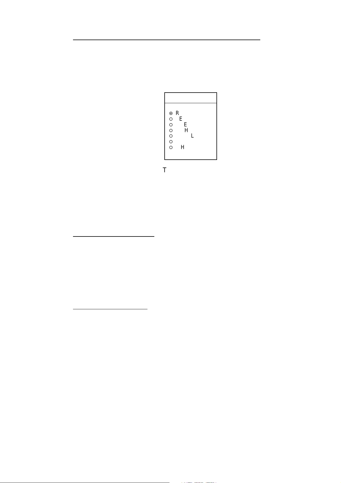
3.8.6 Erasing track
This paragraph shows you how to erase own ship’s track and target tracks. Own
ship’s track can be erased by area, color (MODEL-1700C series only) or
collectively.
Erasing own ship track by area
You can erase own ship’s track by area as below.
1. Press the [MENU] key.
2. Press the [MENU] key followed by CHART SETUP, TRACK & MARK
CONTROL and ERASE T & M soft keys to show the erase menu.
▲
ERASE ALL TRACK
ERASE TRACK BY AREA
ERASE TRACK BY COLOR
ERASE TARGET TRACK
ERASE ALL MARKS & LINES
ERASE MARKS BY AREA
MODEL-1700C series
ERASE
EDIT EDIT
▲
ERASE ALL TRACK
ERASE TRACK BY AREA
ERASE TARGET TRACK
ERASE ALL MARKS & LINES
ERASE MARKS BY AREA
MODEL-1700 series
ERASE
RETURNRETURN
Erase menu
2. Select ERASE TRACK BY AREA and press the EDIT soft key. The menu is
erased and the plotter display appears.
3. Use the cursor pad to place the cursor at one of the corners which will
encompass the area to process.
4. Press the [ENTER] knob.
5. Drag the cursor diagonally to enclose all the track to be erased.
6. Press the [ENTER] knob. You are asked if it is all right to delete t he track.
7. Push the [ENTER] knob to delete the track selected.
8. Press the RETURN soft key.
9. Press the [MENU] key to close the menu.
3-22
3. PLOTTER OPERATIO N
Erasing own ship track by color (MODEL-1700C seri es only)
You may erase own ship’s track by color as follows:
1. Press the [MENU] key followed by CHART SETUP, TRACK & MARK
CONTROL and ERASE T & M soft keys to show the erase menu.
2. Select ERASE TRACK BY COLOR and press the EDIT soft key.
TRACK COLOR
▲
¤
RED
¡
YELLOW
¡
GREEN
¡
LIGHT BLUE
¡
PURPLE
¡
BLUE
¡
WHITE
▼
Track color window
3. Use the cursor pad to select the color you want to erase and push the
[ENTER] knob.
4. Press the [ENTER] knob to erase track color selected.
5. Press the RETURN soft key.
6. Press the [MENU] key to close the menu.
Erasing all own ship track
1. Press the [MENU] key followed by CHART SETUP, TRACK & MARK
CONTROL and ERASE T & M soft keys to show the erase menu.
2. Select ERASE ALL TRACK and press the EDIT soft key.
3. Push the [ENTER] knob to erase all track.
4. Press the RETURN soft key.
5. Press the [MENU] key to close the menu.
Erasing all target tracks
1. Press the [MENU] key followed by CHART SETUP, TRACK & MARK
CONTROL and ERASE T & M soft keys to show the erase menu.
2. Select ERASE TARGET TRACK and press the EDIT soft key.
3. Push the [ENTER] knob to erase all target tracks.
4. Press the RETURN soft key.
5. Press the [MENU] key to close the menu.
3-23
3. PLOTTER OPERATIO N
3.9 Marks
Marks are useful for denoting important events such as a good fishing spot.
Marks can be inscribed in colors (MODEL-1700C series only) of red, yellow,
green, light-blue, purple, blue and white an d seve n shapes.
¡
3.9.1 Entering a mark
1. Place the cursor on the location desired for a mark.
2. Press the MARK ENTRY soft key.
The mark is inscribed in the size, color (MODEL-1700C series only) and shape
selected on the mark setup menu. The default m ark attributes are size, normal;
color, yellow, and shape, hollow circle
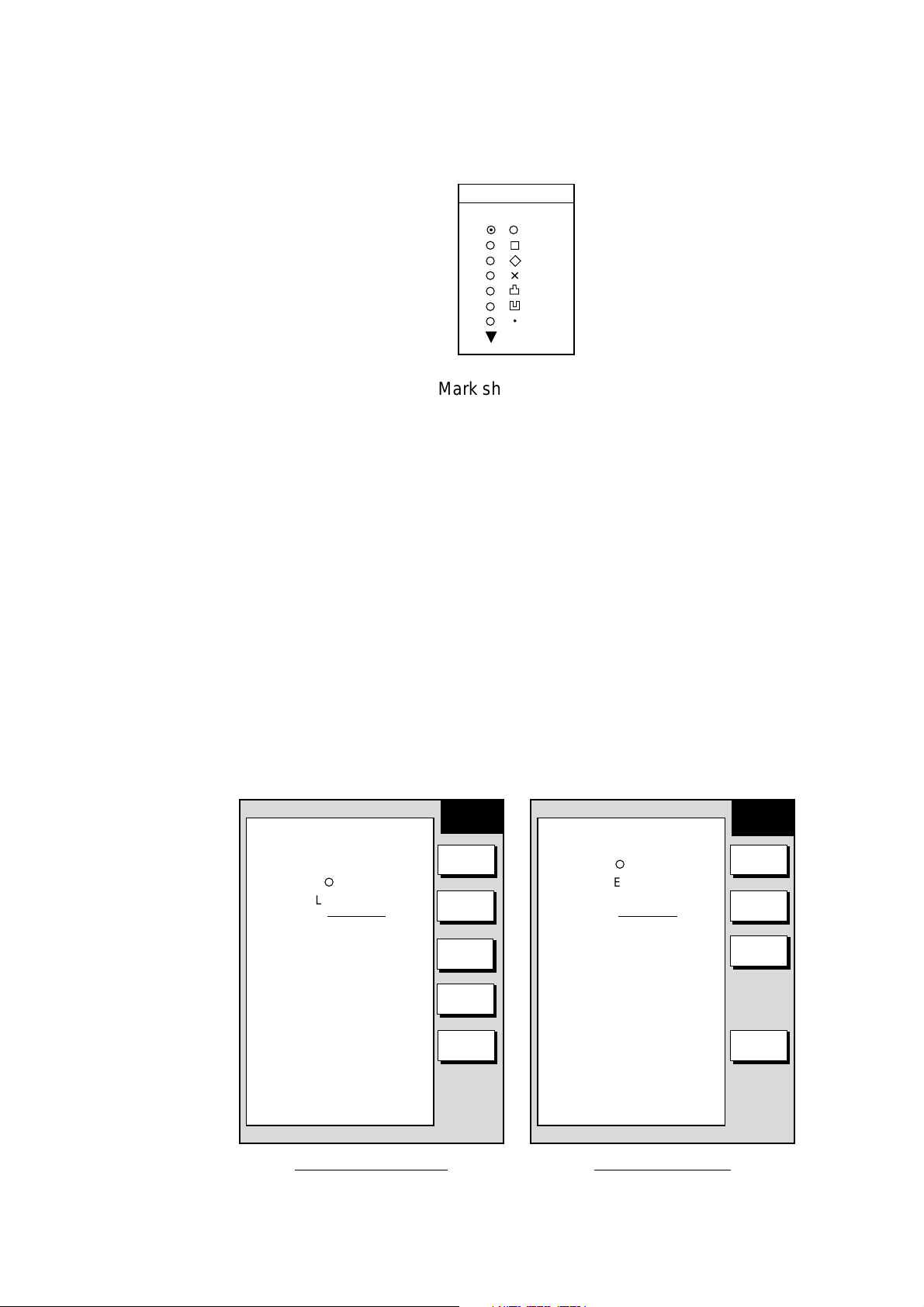
3.9.2 Changing mark attributes
You can select the shape, size and color (MODEL-1700C series onl y) of marks
on the mark
1. Press the [MENU] key to show the menu.
2. Press the CHART SETUP, TRACK CONTROL and MARK & LINE soft keys
to show the mark & line menu.
MARK &
MARK & LINE COLOR
YELLOW
MARK SHAPE
¡
LINE STYLE
MARK SIZE
NORMAL
LINE
MARK
COLOR
MARK
SHAPE
LINE
STYLE
✕
Mark shapes
MARK SHAPE
LINE STYLE
MARK SIZE
¡
NORMAL
MARK &
LINE
MARK
SHAPE
LINE
STYLE
MARK
SIZE
3-24
MARK
SIZE
RETURN
MODEL-1700C series
RETURN
MODEL-1700 series
Mark & line menu
3. For the GD-1700C only, do the following to select mark & line color.
a) Select MARK & LINE COLOR.
b) Pr ess the EDIT soft key.
c) Choose color desired (default setting; yellow).
d) Press the ENTER soft key or [ENTER] knob.
4. Select MARK SHAPE.
5. Press the EDIT soft key.
MARK SHAPE
▲
¤
¡
¡
¡
✕
¡
¡
¡
¡
▼
Mark shape window
3. Select mark shape and press the ENTER soft key.
4. Select MARK SIZE.
5. Press the EDIT soft key.
6. Select NORMAL (default setting) or SMALL.
7. Press the ENTER soft key or [ENTER] knob.
8. Press the RETURN soft key.
9. Press the [MENU] key to close the menu.
3. PLOTTER OPERATIO N
3.9.3 Connecting marks
You may wish to connect marks with lines. This feature can be used to mark
boundaries, etc.
1. Press the [MENU] key followed by CHART SETUP, TRACK & MARK
CONTROL and MARK & LINE SETUP soft keys to show the mark & line
menu.
MARK & LINE COLOR
YELLOW
MARK SHAPE
¡
LINE STYLE
MARK SIZE
NORMAL
MARK &
LINE
MARK
COLOR
MARK
SHAPE
LINE
STYLE
MARK
SIZE
RETURN
MARK SHAPE
¡
LINE STYLE
MARK SIZE
NORMAL
MARK &
LINE
MARK
SHAPE
LINE
STYLE
MARK
SIZE
RETURN
MODEL-1700C series
Mark & line setup menu
MODEL-1700 series
3-25

3. PLOTTER OPERATIO N
2. Select MARK STYLE.
3. Press the EDIT soft key.
4. Select line style desired and press the ENTER soft key or [ENTER] knob.
5. Press the RETURN soft key followed by the [MENU] key to close the menu.
When you wish to enter marks without connection them with lines, select the line
style “single dot” at step 5 in the above procedure.
3.9.4 Erasing marks
MARK LINE
▲
¤
¡
¡
¡
▼
Mark line window
Erasing an individual mark
1. Operate the cursor pad to place the cursor on the mark you want to erase.
2. Press the [CLEAR] key to erase the mark.
Note: To erase a line, place the cursor on the mark which encloses the line, and
then press the [CLEAR] key. Place the cursor at t he intersecting points of
two lines will erase both lines.
Erasing all marks, lin es
You can erase all marks and lines. Be absolutely sure you want to erase all marks
and lines; erased marks and lines cannot be restored.
1. Press the [MENU] key followed by CHART SETUP, TRACK & MARK
CONTROL and ERASE T & M soft keys to show the erase menu.
2. Select ERASE ALL MARKS & LINES and press the EDIT soft key.
3. Push the [ENTER] knob to erase all marks and lines.
4. Press the RETURN soft key.
5. Press the [MENU] key to close the menu.
3-26
 Loading...