

Furuno USA 9ZWRTR051, 9ZWRTR058, 9ZWRTR070 Users Manual
2. RADAR OPERATION
This chapter covers radar operation, including the optional ARPA (Automatic
Radar Plotting Aid) function. Connection of a 1833/1933/1943 series network
radar equipped with the ARPA circuit board is required.
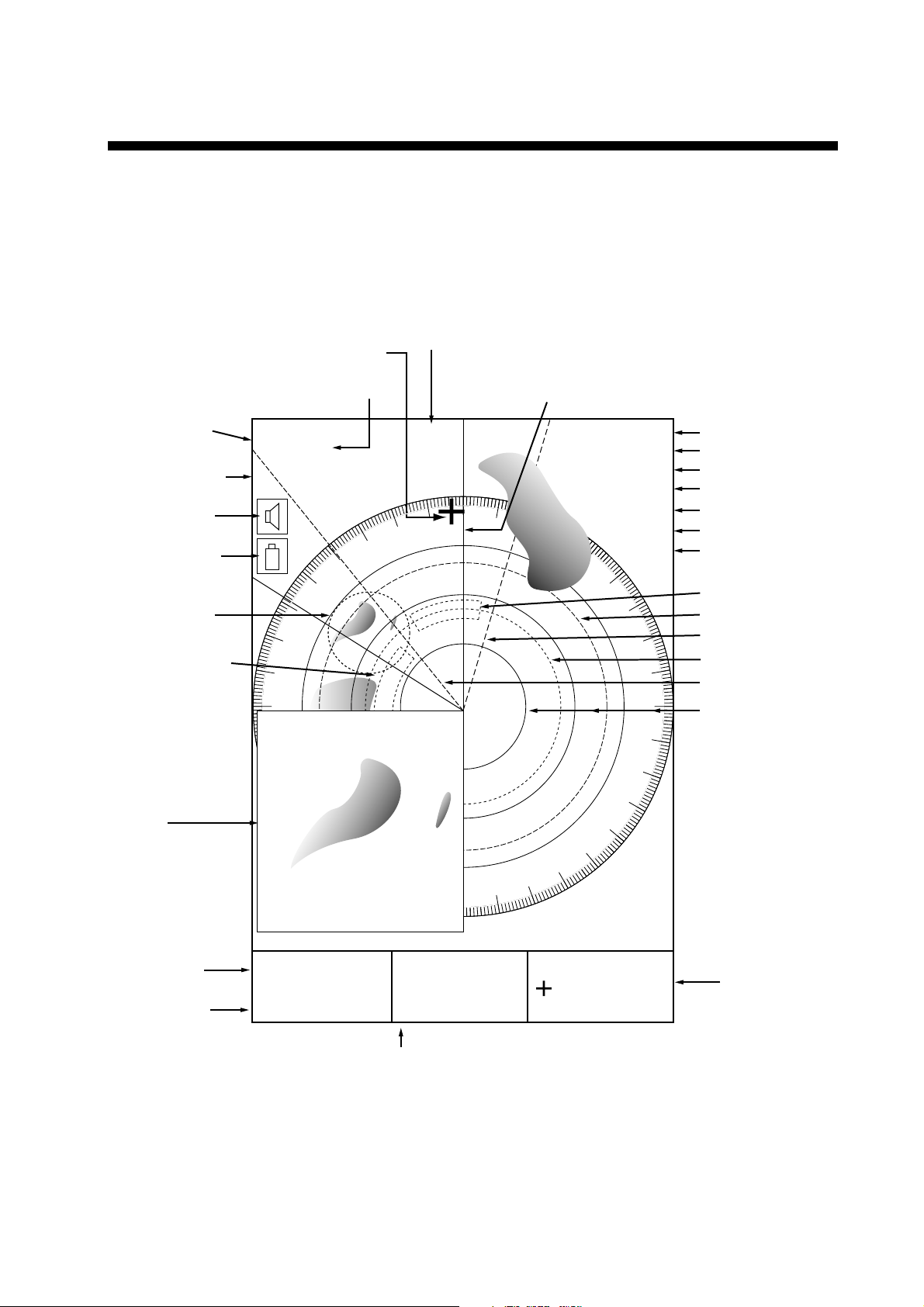
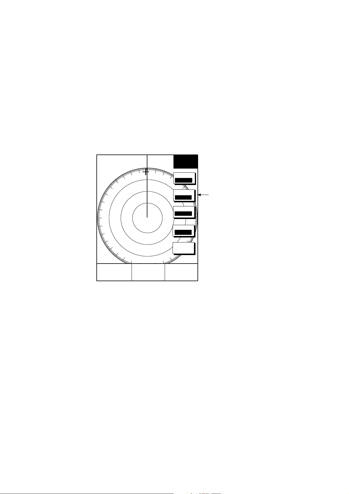
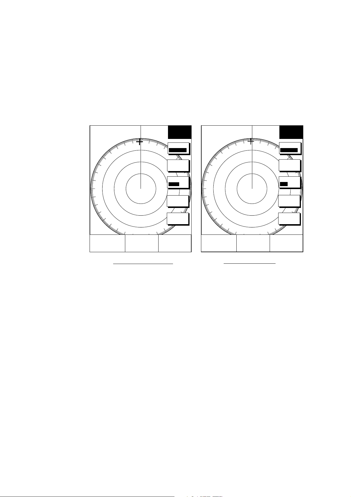
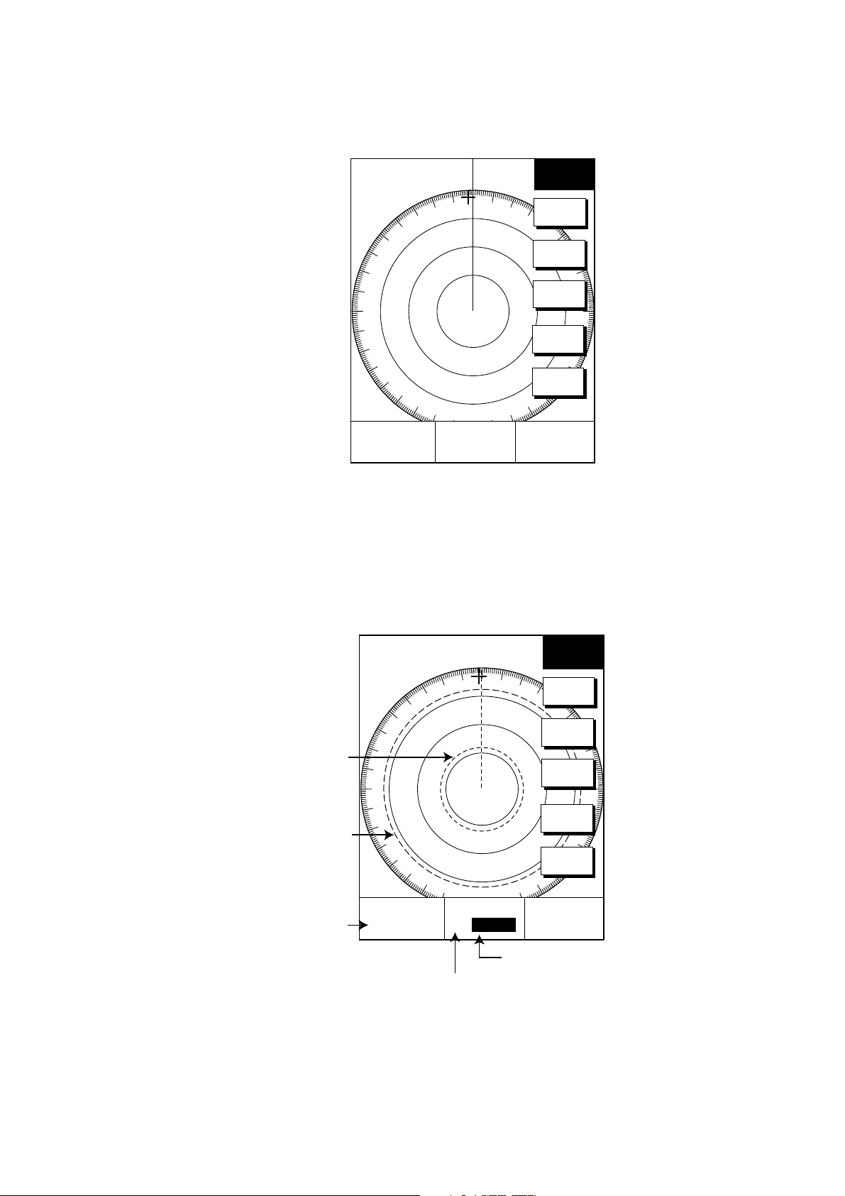
2.1 Radar Display
Range/
range ring
interval
Presentation
mode
Alarm icon
Battery icon
Zoom area
Guard zone 1
12/
HU
Cursor
Pulselength
3nm
SP
Bearing
319. 9
R
Heading line
TRAIL 30m
02m30s
G2 OUT
G1 IN
ES 2
IR L
NR
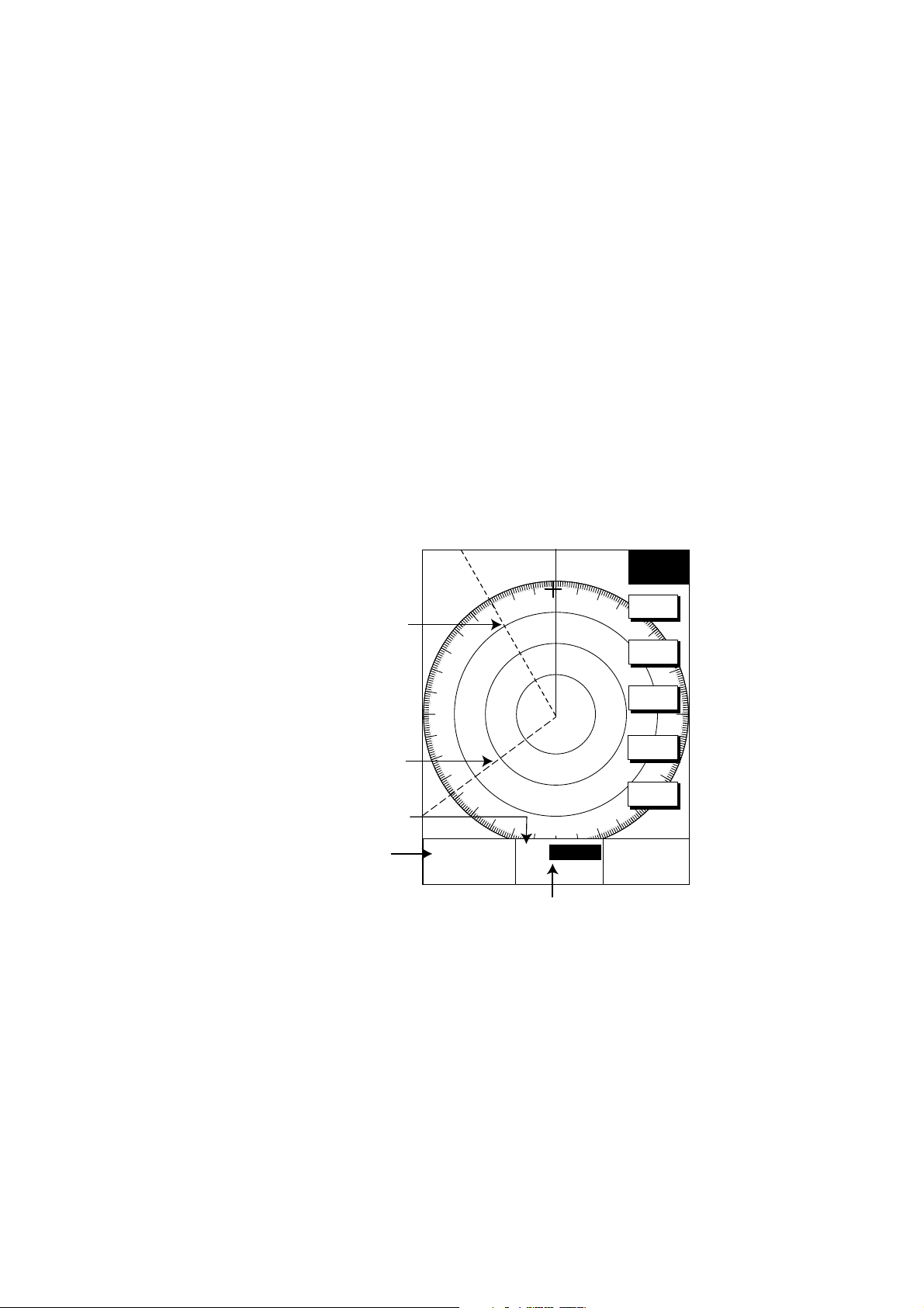
Trail time
Trail elapsed time
Guard zone 1
Guard zone 2
Echo stretch
Interference rejector
Noise rejector
Guard zone 2
VRM2
EBL1
VRM1
EBL2
Range ring
Zoom
window
EBL1 range
VRM1 range
V1
17.0 R
8.2nm
E2 320.1 R
V2 10.9nm
EBL2 bearing, VRM2 range
Radar display
359.9 R
E1
11.7nm
Cursor range
and bearing
2-1
2. RADAR OPERATION
2.2 Transmitting, Stand-by
1. Press the RADAR TX soft key to show the radar picture.
2. When the radar picture is not required, but you want keep it in a state of
readiness, press the RADAR TX soft key to go into the standby mode. ST-BY
appears on the display and the RADAR soft key shows STBY as its current
option.
2.3 Adjusting the Gain
The gain circuit adjusts the gain (sensitivity) of the radar receiver. It works in
precisely the same manner as the volume control of a broadcast receiver,
amplifying the signals received.
The proper setting is such that the background noise is just visible on the screen.
If you set up for too little gain, weak echoes may be missed. On the other hand
excessive gain yields too much background noise; strong targets may be missed
because of the poor contrast between desired echoes an d the background noise
on the display.
To adjust receiver gain, transmit on long range, and then do the following.
1. Press the [GAIN] key to display the soft key for adjustment of gain.
3nm
12/ 319.9°
SP
HU
E1 °R
V1 nm
E2 °R
V2 nm
Linear amp Log amp
R
GAIN
ADJUST
GAIN
A/C
SEA
A/C
RAIN
FTC
RETURN
359.9
+
11.7nm
°
R
3nm
12/ 319.9°
SP
HU
E1 °R
V1 nm
E2 °R
V2 nm
R
GAIN
ADJUST
GAIN
A/C
SEA
A/C
RAIN
A/C AT
ON OFF
RETURN
359.9
+
11.7nm
°
R
2-2
Gain adjust menu
2. Press the GAIN soft key to show the GAIN SENSITIVITY window.
GAIN SENSITIVITY
▲
¡
AUTO ROUGH/OCEAN
¡
AUTO MODERATE
¡
AUTO CALM/HARBOR
¤
MAN
▼
Gain sensitivity window
3. Operate the cursor pad to select AUTO ROUGH/OCEAN, AUTO MODERATE,
AUTO CALM/HARBOR or MAN (manual) as appropriate.
4. For manual adjustment, rotate the [ENTER] knob to adjust the gain. The
adjustable range is 0-100(%).
5. Press the RETURN soft key to finish.
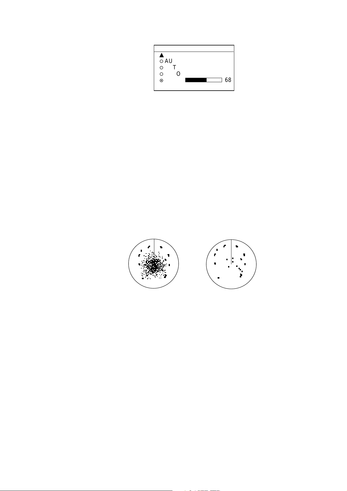
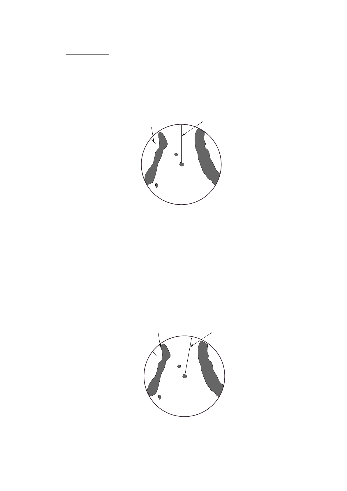
2.4 Reducing Sea Clutter
2. RADAR OPERATION
68
Echoes from waves can be troublesome, covering the central part of the display
with random signals known as “sea clutter”. The higher the waves, and the higher
the antenna above the water, the further the clutter will extend. Sea clutter
appears on the display as many small echoes which m ight affect radar
performance. (See the left-hand figure in the figure below.) When sea clutter
masks the picture, adjust the A/C SEA circuit to reduce the clutter.
Sea clutter at
screen center
Effect of A/C SEA
2.4.1 How the A/C SEA circuit works
The A/C SEA circuit reduces the amplification of echoes at short ranges (where
clutter is the greatest) and progressively increases am plif ication as the range
increases, so amplification will be normal at those ranges where there is no sea
clutter.
A/C SEA adjusted;
sea clutter suppressed
2-3
2. RADAR OPERATION
2.4.2 Adjusting A/C SEA
The proper setting of the A/C SEA should be such that the clutter is broken up
into small dots, and small targets become distinguishable.
1. Press the [GAIN] key.
2. Press the A/C SEA soft key to show the A/C SEA setting window.
3. Operate the cursor pad to select AUTO LOW, AUTO MEDIUM, AUTO HIGH
or MAN (manual).
4. When MAN is selected, rotate the [ENTER] knob to adjust the A/C SEA. The
adjustable range is 0-100(%).
5. For the log amp type network radar (MODEL-1833/C, 1933/C, 1943/C), A/C
SEA and A/C RAIN can be automatically adjusted. Press the soft key A/C AT
to turn automatic adjustm ent on or off as appropriate.
6. Press the GAIN or RETURN soft key to finish.
A/C SEA
▲
¡
AUTO ROUGH/OCEAN
¡
AUTO MODERATE
¡
AUTO CALM/HARBOR
¤
MAN
▼
A/C SEA setting window
68
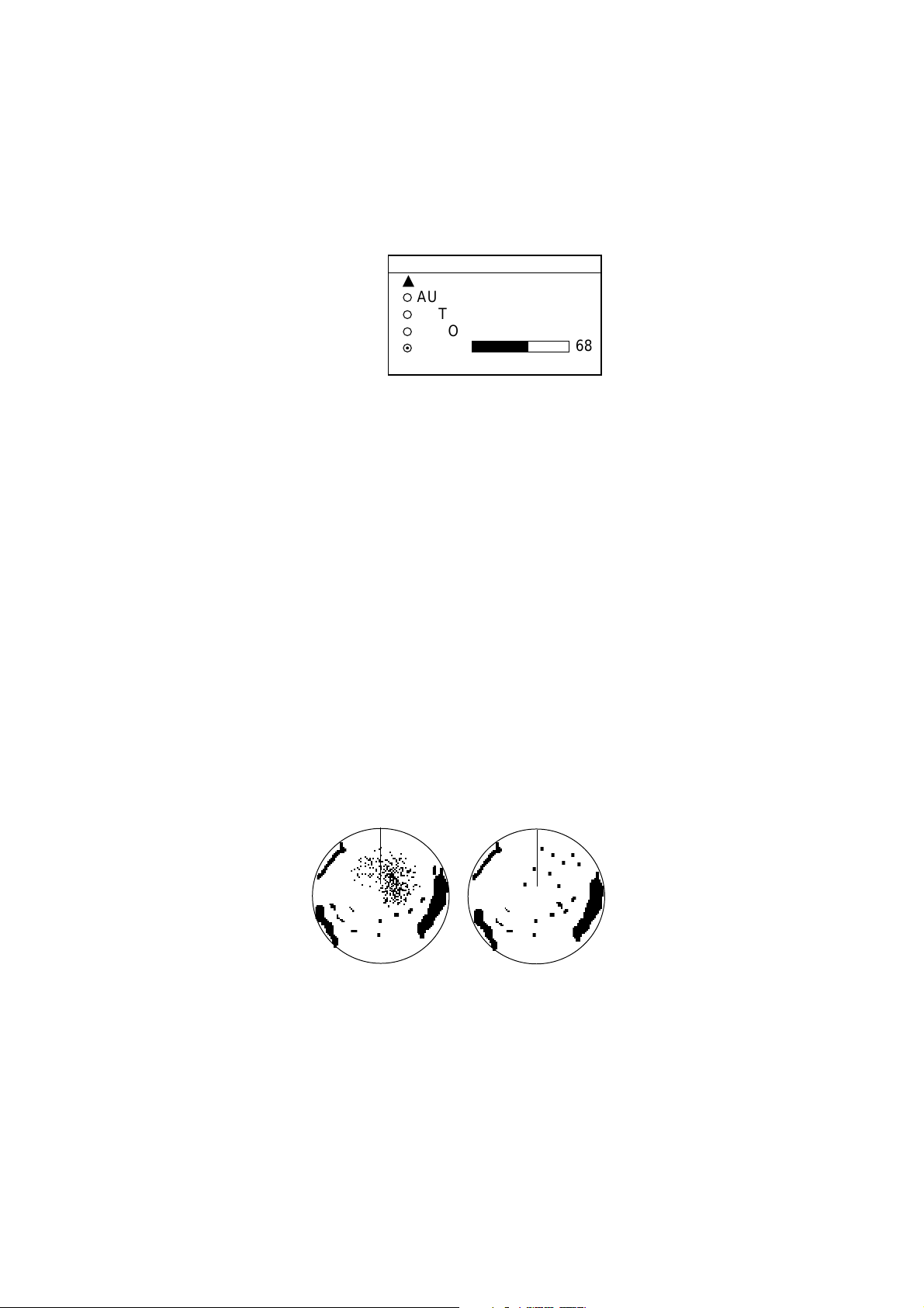
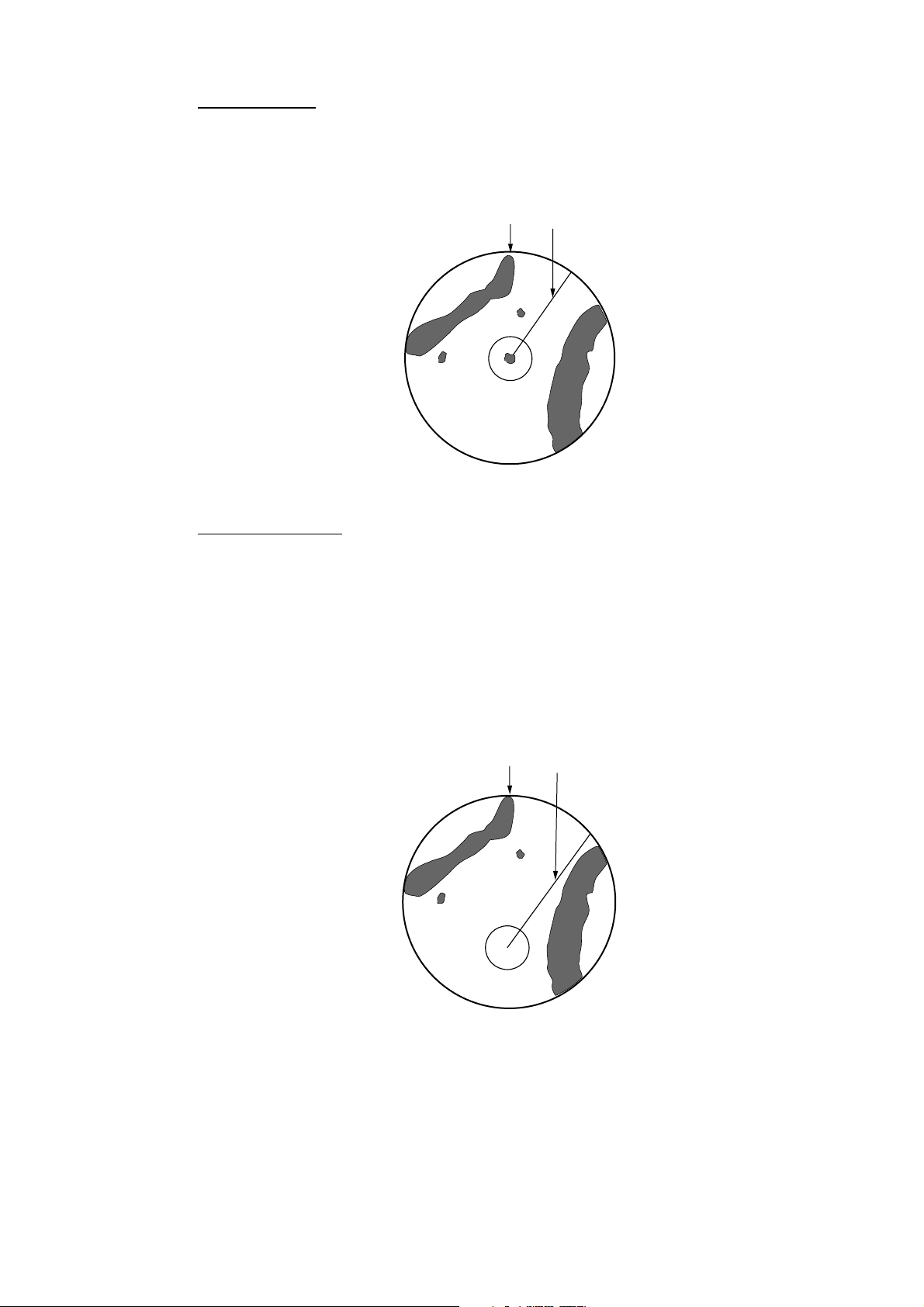
2.5 Reducing Precipitation Clutter
The vertical beamwidth of the antenna is designed to see surface targets even
when the ship is rolling. However, by this design the unit will also detect rain
clutter (rain, snow, hail, etc.) in the same manner as normal targets. The
illustration in below shows the appearance of rain clutter on the display.
[A/C RAIN] control
off
Effect of A/C RAIN
[A/C RAIN] control
adjusted
2-4
2.5.1 Adjusting the A/C RAIN
When rain clutter masks echoes, adjust the A/C RAIN circuit. This circuit splits up
these unwanted echoes into a speckled pattern, making recognition of solid
targets easier.
1. Press the [GAIN] key to show the GAIN ADJUST menu.
2. Press the A/C RAIN soft key to show the A/C RAIN window.
A/C RAIN setting window
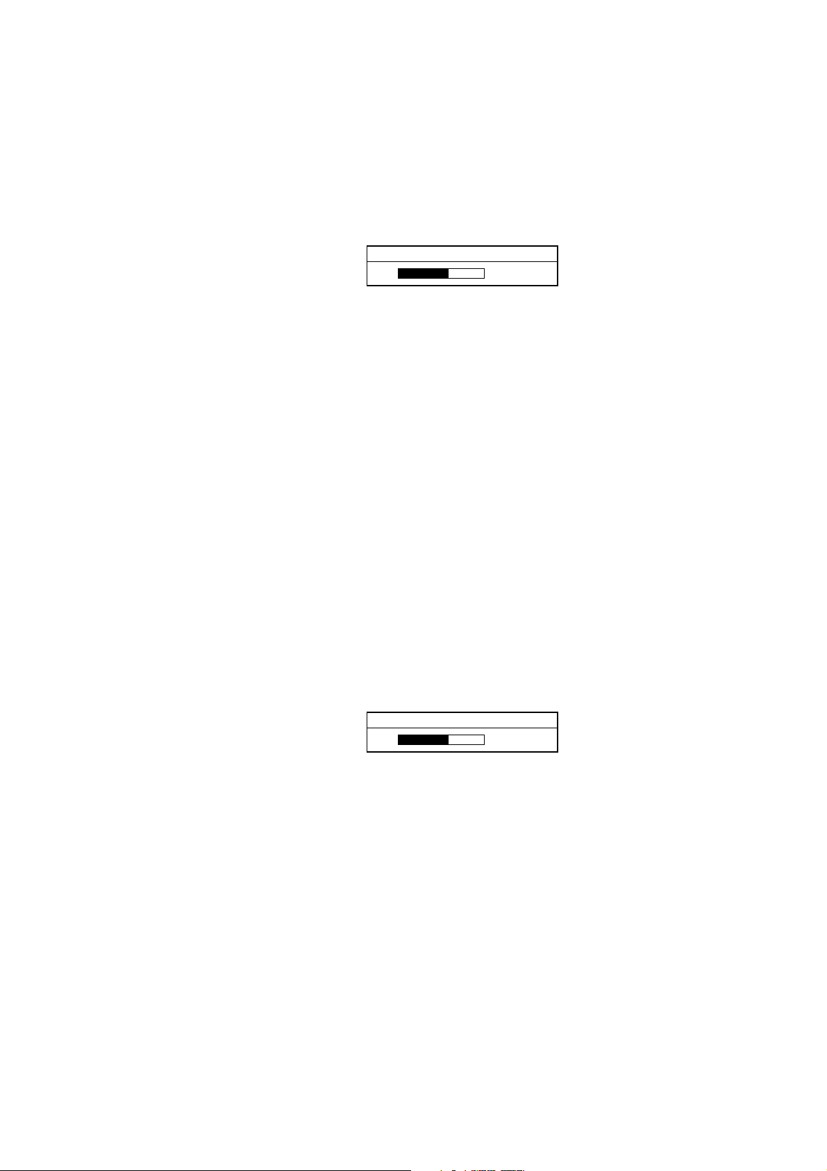
3. Rotate the [ENTER] knob to adjust the A/C RAIN affect. The current level is
shown on the A/C RAIN level bar in the A/C RAIN window, and the adjustable
range is 0 to 100(%).
4. Press the A/C RAIN or RETURN soft key to finish.
2. RADAR OPERATION
A/C RAIN
68
2.5.2 Adjusting the FTC (linear amp-type network radar onl y)
To suppress rain clutter from heavy storms or scattered rain clutter, adjust FTC.
The FTC circuit splits up these unwanted echoes into a speckled pattern, making
recognition of solid targets easier.
Note:In addition to reducing clutter, the FTC can be used in fine weather to
clarify the picture when navigating in conf ined waters. However, with the
circuit activates the receiver is less sensitive. Therefore, turn off the circuit
when its function is not required.
1. Press the [GAIN] key to show the GAIN ADJUST menu.
2. Press the FTC soft key to show the FTC window.
FTC
68
FTC setting window
3. Rotate the [ENTER] knob to adjust FT C circuit affect. The adjustable range is
0-100(%).
4. Press the GAIN or RETURN soft key to finish.
2-5
2. RADAR OPERATION
2.6 Tuning the Receiver
The radar receiver can be tuned automatically or manually, and the default tuning
method is automatic.
2.6.1 Manual tuning
If you require manual tuning do the f ollowing:
1. Press the [MENU] key to display the main menu.
2. Press the RADAR DISPLAY SETUP soft key.
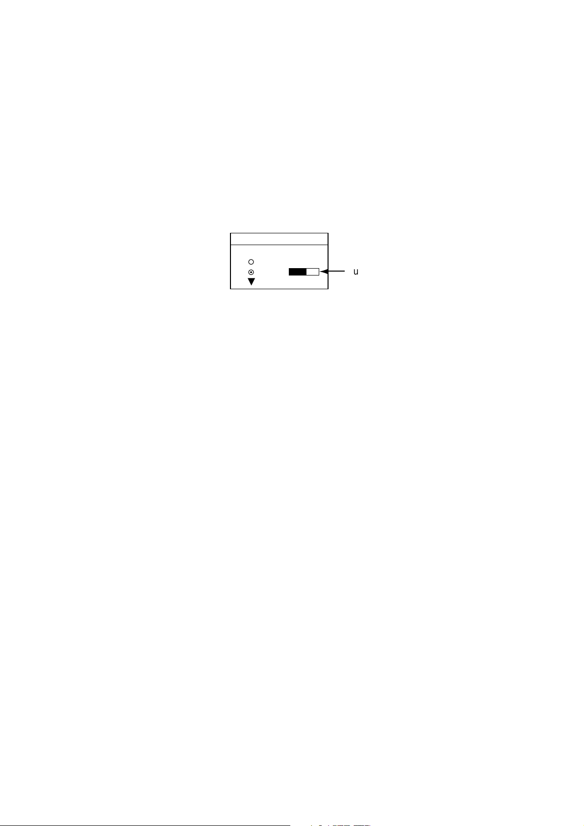
3. Select TUNING and press the EDIT soft key.
TUNE
▲
¡
AUTO
¤
MAN
▼
Tuning bar
Tuning window
4. Choose MAN.
5. Adjust the [ENTER] knob to show the longest tuning b ar.
6. Press the RETURN soft key.
7. Press the [MENU] key to close the menu.
2-6
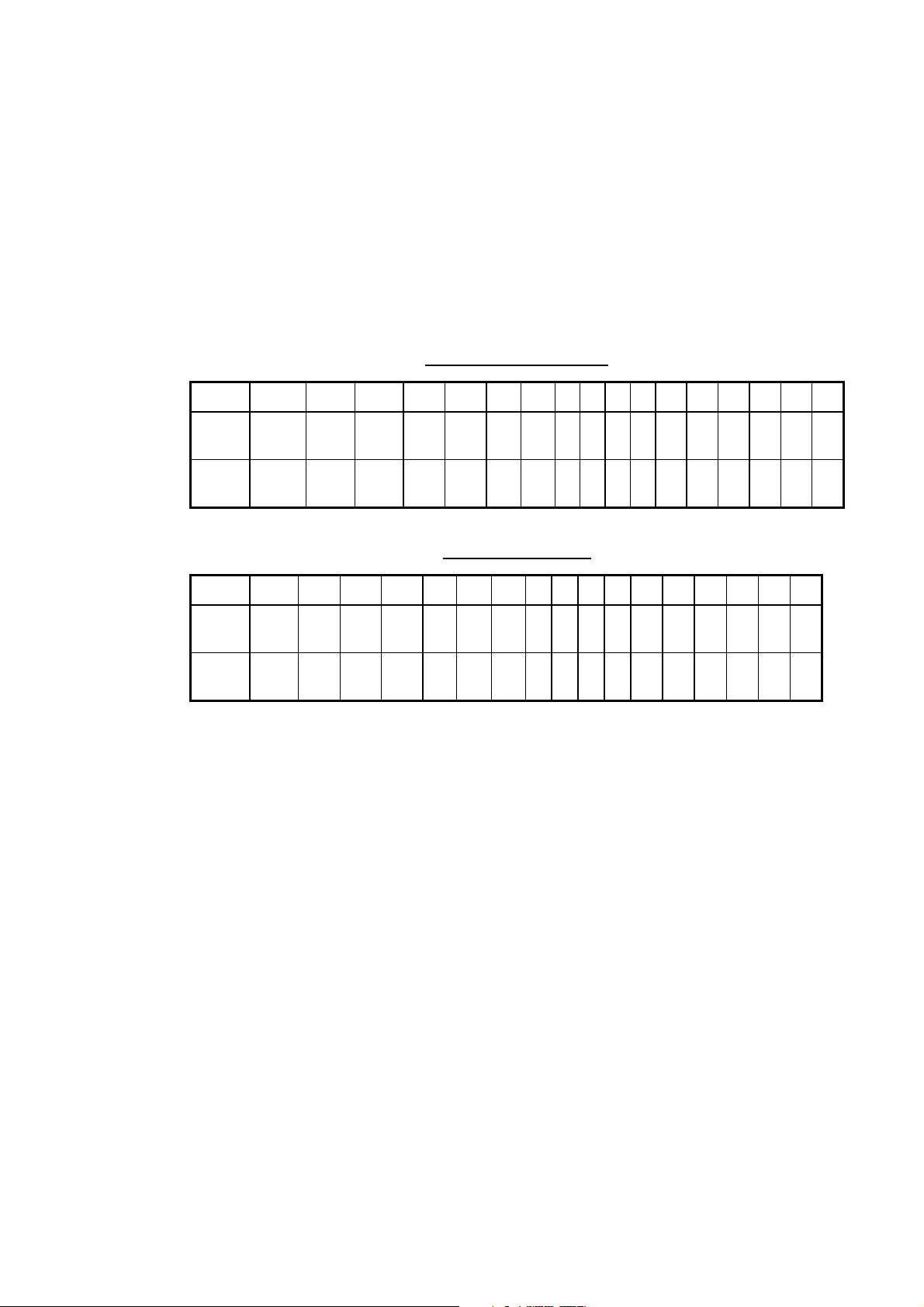
2.7 Selecting the Range Scale
The range selected automatically determines the range ring interval, the num ber
of range rings, pulselength and pulse repetition rate, for optimal detection
capability in short to long ranges.
The range, range ring interval and pulselength ap pear at the top left-hand corner
of the display.
Press the [RANGE (+ or -)] key to change the range scale.
Range scales (nm, sm)
Range 0.125 0.25 0.5 0.75 1 1.5 2 3468121624364864
2. RADAR OPERATION
Ring
Interval
# of
Rings
0.0625 0.125 0.125 0.25 0.25 0.5 0.5 11223 4 6121216
2 2 4 3 4 3 4 34344 4 4 3 4 4
Range scales (km)
Range 0.25 0.5 0.75 1 1.5 2 3 4 6 6 8 12 16 24 36 48 64
Ring
Interval
# of
Rings
0.125 0.25 0.25 0.25 0.5 0.5 0.5 1 1 2 2 3 4 6 12 12 16
2 2 3 4 3434344444344
Note: Maximum range depends on the network radar connected as below.
1722, 1722C: 24 nm
1732, 1732C, 1752, 1752C, 1833, 1833C; 36 nm
1762, 1762C, 1933, 1933C: 48 nm
1943, 1943C: 64 nm
2-7
2. RADAR OPERATION
2.8 Pulselength
The pulselength in use is displayed at the upper left corner of the display.
Appropriate pulselengths are preset to individual rang e scales and function keys.
Therefore, you are not usually required to select them. If you are not satisfied with
the current pulselength setting, however, it is possible to change it for the 3 and 6
kilometer ranges as below. Generally, select a long pulse for longer detection
range and short pulse for better range discrimination.
1.5 nm (3 km): Short pulse, middle pulse
3 nm (6 km): Middle pulse, long pulse
1. Press the SIGNAL PROC. soft key to show the soft keys for signal processing.
3nm
12/ 319.9°
SP
HU
R
SIGNAL
PROCESS
I. REJ
LOW
E. AVG
OFF
Log amplifier model only;
not displayed on linear
E1 °R
V1 nm
E2 °R
V2 nm
PULSE
LONG
E. STR
LOW
RETURN
359.9
+
11.7nm
°
R
amplifier model
Signal process soft keys
2. Press the PULSE SP (MP/LP) soft key to select the pulse width setting. Soft
key shows the current setting. (1.5 nm: short pulse and middle pulse, 3 nm:
middle pulse and long pulse)
3. Press the RETURN soft key to finish.
2-8
Note: This function is available only when 3 nm or 1.5 nm is selected.
2.9 Presentation Mode
This unit provides four presentation modes: head-up, course-up, north-up and
true motion.
Heading input required for modes other t han head-up.
2.9.1 Selecting a presentation mode
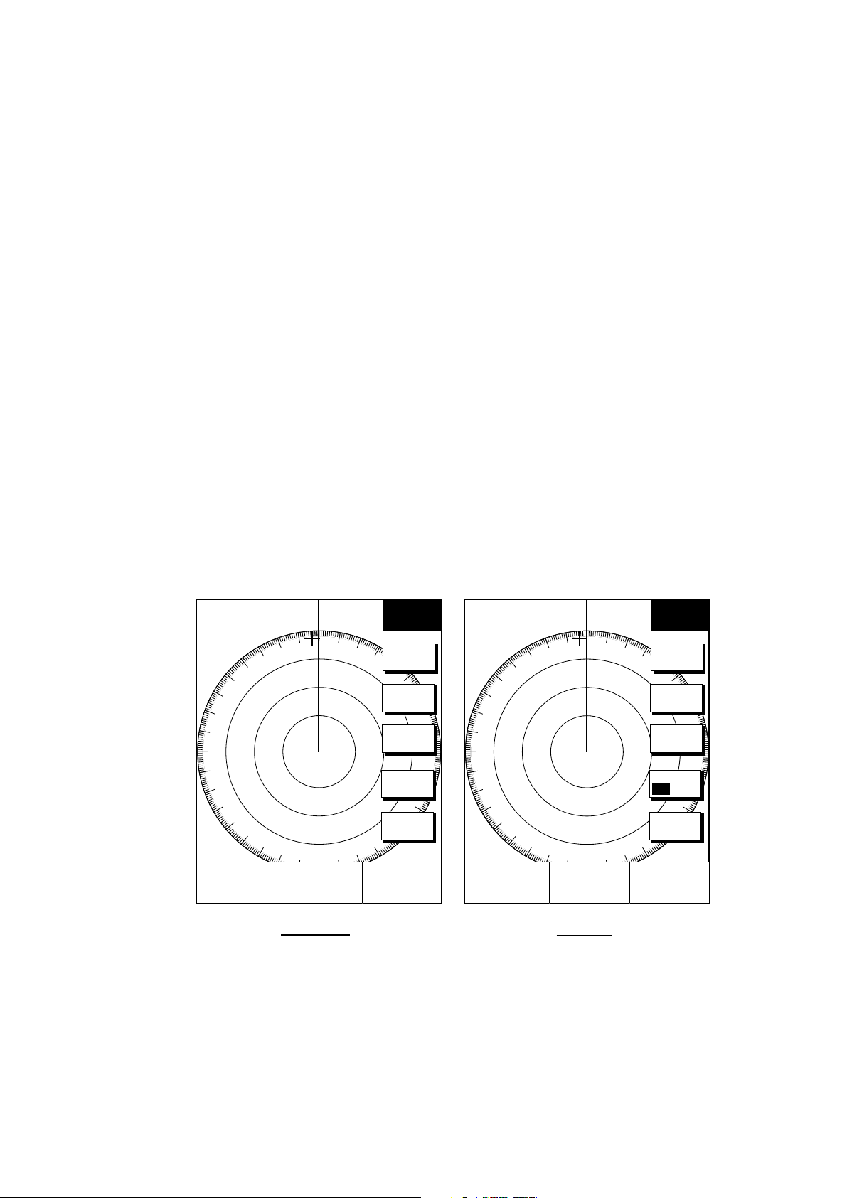
1. Press the RADAR DISPLAY soft key to show the radar display soft keys.
2. RADAR OPERATION
3nm
12/ 319.9°
SP
HU
E1 °R
V1 nm
E2 °R
V2 nm
R
RADAR
DISPLAY
MODE
HD UP
SHIFT
RINGS
MED
HL OFF
RETURN
359.9
+
11.7nm
°
R
3nm
12/ 319.9°
SP
HU
E1 °R
V1 nm
E2 °R
V2 nm
R
RADAR
DISPLAY
MODE
HD UP
SHIFT
RINGS
ON OFF
HL OFF
RETURN
359.9
+
11.7nm
°
R
MODEL-1700C series MODEL-1700 series
View soft keys
2. Press the MODE soft key. Each pressing of the key changes the presentation
mode and the presentation mode indication in the sequence of North-up, True
Motion, Head-up, and Course-up.
Note:When there is no heading data input, the MODE soft key does not appear.
2-9
2. RADAR OPERATION
2.9.2 Presentation mode overview
Head-up (HU)
A display without azimuth stabilization in which the line connecting the center with
the top of the display indicates own ship’s headin g. The target pips are painted at
their measured distances and in their directions relative to own ship’s heading.
A short line on the bearing scale is the north marker indicating compass north.
North marker
Head-up presentation mode
Heading Line
Course-up (CU)
An azimuth stabilized display in which a line connecting the center with the top of
the display indicates own ship’s intended course (namely, own ship’s previous
heading just before this mode has been selected).
Target pips are painted at their measured distances and in their directions relative
to the intended course which is maintained at the 0-degree position while the
heading line moves in accordance with ship’s yawing and course cha nges. This
mode is useful to avoid smearing of picture during course change. After a course
change, press the [CLEAR] key to reset the picture orientation if you wish to
continue using the course-up mode.
2-10
North marker
Course-up presentation mode
Heading Line
2. RADAR OPERATION
North-up (NU)
In the north-up mode, target pips are painted at their measured distances and in
their true (compass) directions from own ship, north being maintained UP of the
screen. The heading line changes its direction according to the ship’s heading.
North
North-up presentation mode
Heading Line
True motion (TM)
Own ship and other moving objects move in accordance with their tr ue courses
and speeds. All fixed targets, such as landmasses, appear as stationary echoes.
When own ship reaches a point corresponding to 75 % of the radius of the
display, the own ship is automatically reset to a point of 75 % radius opposite to
the extension of the heading line passing through the display center. Resetting
can be made at any moment before the ship reaches the limit by pressing the
[CLEAR] key. Automatic resetting is preceded by a beep sound.
North
True motion presentation mode
Heading Line
LOSS OF COMPASSS SIGNAL: When the compass signal is lost, the
presentation mode automatically becomes head-up and the compass readout at
the screen top shows xxx.x°. Once the compass signal is restored the
presentation mode in use when the compass signal was lost is restored.
2-11
2. RADAR OPERATION
2.10 Measuring the Range
You can measure the range to a target three ways: by the range rings, by the
cursor, and by the VRM (Variable R ange Marker).
2.10.1 Measuring range by range rings
Count the number of rings between the center of the display and the target.
Check the range ring interval and judge the distance of the echo from the inner
edge of the nearest ring.
To turn the rings on/off, do the following:
1. Press the RADAR DISPLAY soft key.
3nm
12/ 319.9°
SP
HU
E1 °R
V1 nm
E2 °R
V2 nm
R
RADAR
DISPLAY
MODE
HD UP
SHIFT
RINGS
MED
HL OFF
RETURN
359.9
+
11.7nm
°
R
3nm
12/ 319.9°
SP
HU
E1 °R
V1 nm
MODEL-1700C series MODEL-1700 series
View soft keys
2. Press the RINGS soft key to display the range rings.
3. Press the RETURN soft key to finish.
R
E2 °R
V2 nm
RADAR
DISPLAY
MODE
HD UP
SHIFT
RINGS
ON OFF
HL OFF
RETURN
359.9
+
11.7nm
°
R
2.10.2 Measuring range by cursor
Operate the cursor pad to place the cursor intersection on the inside edge of the
target echo. The range to the target, as well as the bearing, appears to the right
of “+” at the bottom of the display.
2-12
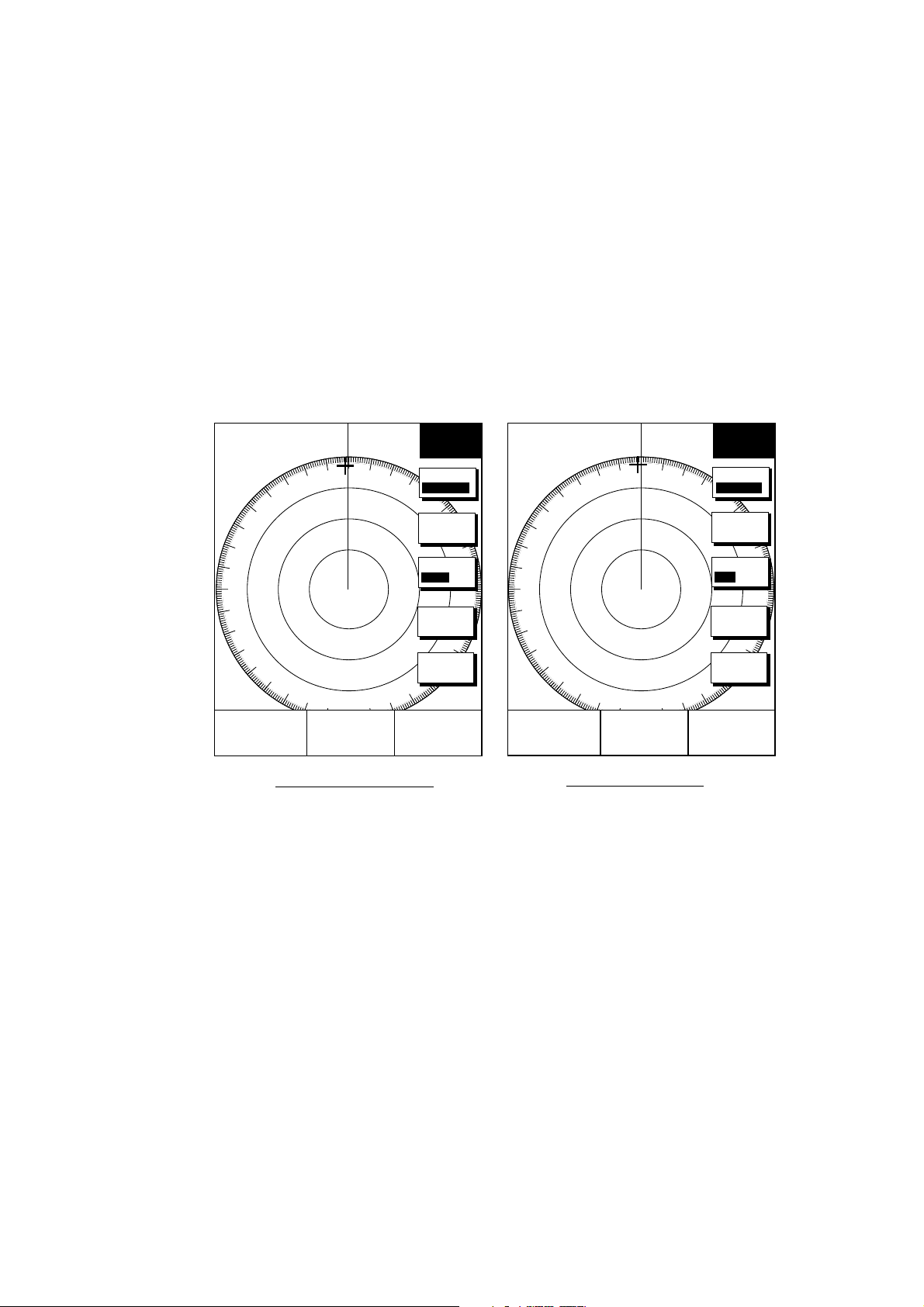
2.10.3 Measuring range by VRM
1. Press the [EBL/VRM] key to display the EBL and VRM soft keys.
2. RADAR OPERATION
3nm
12/ 319.9°
SP
HU
E1 °R
V1 nm
E2 °R
V2 nm
R
EBL
VRM
EBL1
VRM1
OFFSET
EBL2
VRM2
359.9
+
11.7nm
°
R
EBL/VRM soft keys
2. Press the VRM1 (dotted ring) or VRM2 (dashed line) soft key to select VRM
desired. The selected VRM and its indication (at the bottom center) is
highlighted.
3. Rotate the [ENTER] knob the place the VRM on the insi de edge of a target
echo. Read the VRM indication to find range.
VRM1
(Dotted line)
VRM2
(Dashed line)
VRM1 range
3nm
12/ 319.9°
SP
HU
E1 °R
V1 3.45nm
E2 °R
V2 9.88nm
R
359.9° R
+
11.7nm
EBL
VRM
EBL1
VRM1
OFFSET
EBL2
VRM2
Active marker is highlighted.
VRM2 range
How to measure range with the VRM
2-13

2. RADAR OPERATION
2.10.4 Erasing a VRM
Press appropriate VRM soft key and press the [CLEAR] key.
2.10.5 Erasing EBL/VRM data boxes
The EBL/VRM data boxes are automatically erased any time an EBL or VRM is
turned off. If you do not require the EBL/VRM data boxes during operat ion of an
EBL or VRM, you can erase them by pressing the [CLEAR] key. The data boxes
will be redisplayed when an EBL or VRM is operated or an EBL/VRM data box is
moved.
2.10.6 Moving EBL/VRM data boxes
When an EBL/VRM data box is obscuring a wanted target you can move it to
another location. Place the cursor in the data box and press the [ENT ER] knob.
Use the cursor pad to move the box to new location and then press the [ENTER]
knob.
2-14
2.11 Measuring the Bearing
There are two ways to measure the bearing to a target: by the cursor, and by the
EBL (Electronic bearing Line).
2.11.1 M easuring bearing by cursor
Operate the cursor pad to bisect the target with the cursor intersection. The
bearing to the target appears at the bottom to the right of “+” at the bottom of the
display.
2.11.2 Measuring bearing by EBL
1. Press the [EBL/VRM] key.
2. Press the EBL1 (dotted line) or EBL2 (dashed line) soft key to select EBL
desired. The selected EBL and its indication (at the bottom center) is
highlighted.
3. Rotate the [ENTER] knob to bisect the target echo with the EBL. Read the
EBL indication to find bearing.
4. To erase an EBL, press the EBL1/EBL2 soft key again.
2. RADAR OPERATION
(Dotted line)
(Dashed line)
EBL2 bearing
EBL1 bearing
2.11.3 Erasing an EBL
3nm
12/ 319.9°
SP
R
EBL
VRM
HU
EBL1
EBL1
VRM1
OFFSET
EBL2
E1 330.1°R
V1 nm
E2 232.3°R
V2 nm
Active marker is highlighted.
EBL2
VRM2
359.9
+
11.7nm
How to measure bearing with the EBL
°
R
Press appropriate EBL soft key and press the [CLEAR] key.
2-15
 Loading...