

Furuno USA 9ZWR110 Users Manual

S2E-17-0056_A
INSTALLATION
MANUAL
MODEL: WEATHER RADAR
TYPE: WR110
www.furuno.com
S2E-17-0056_A
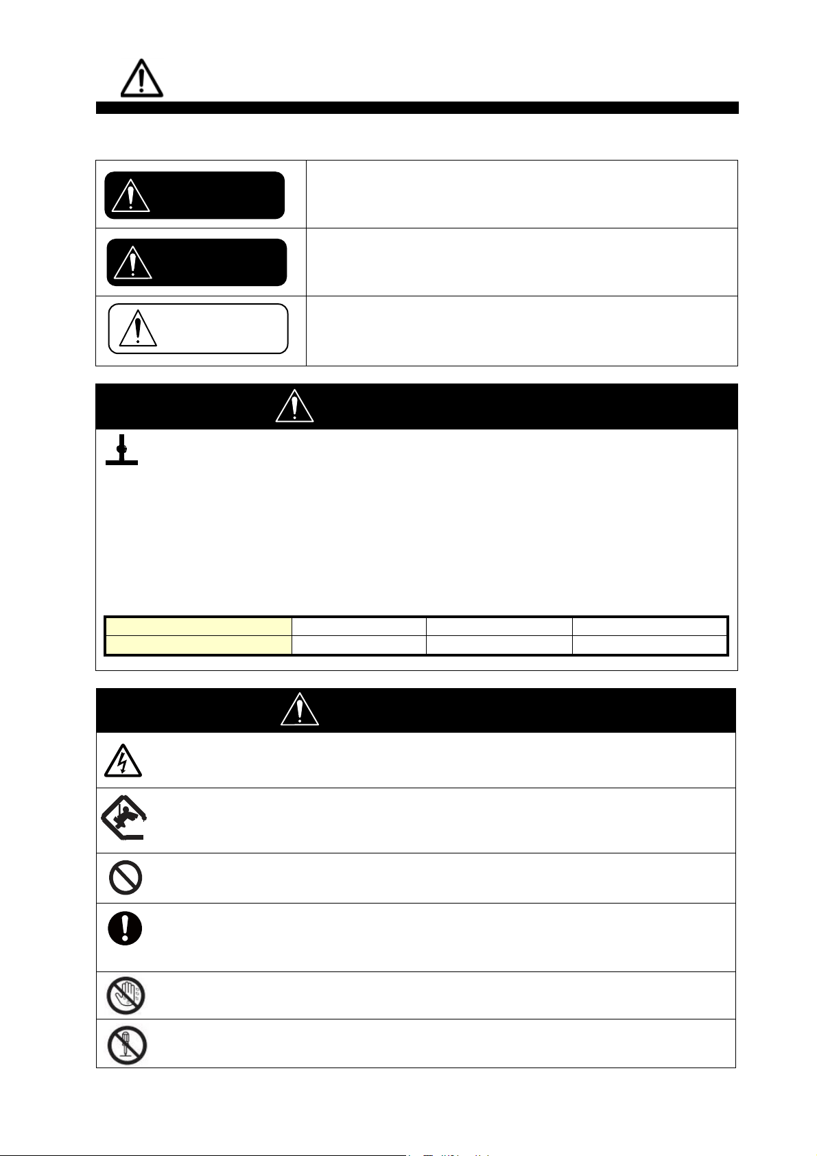
Indicates a hazardous situation which, if not avoided, will result
in death or serious injury.
Indicates a potentially hazardous situation which, if not
avoided, could result in death or serious injury.
Indicates a potentially hazardous situation which, if not
avoided, can result in minor or moderate injury.
WARNING
Radio Frequency Radiation Hazard
The radar antenna sends the electromagnetic radio frequency (RF) energy. This energy can
be dangerous to you, especially on your eyes. Do not look at the radiator or near the
antenna when the antenna is rotating.
The distances at which RF radiation levels of 100 W/m 2, 50 W/m 2, and 10 W/m 2 exist are
shown in the table.
DO NOT go near more than 12.7m (Safety standard is 10 W/m 2).
NOTE: The value is applied for being installed in the public space. And it is defined on human
body surface over any 6-minutes period with the flux density averaged from the measurement.
Distance from Antenna
-m
-m
12.7m
Power flux density
100 W/m
2
50 W/m 2
10 W/m 2
WARNING
Do not open the radome.
Electrical shock can occur. Only qualified personnel should work inside the equipment.
Turn off the circuit breaker in the JCU if it has to open the radome.
Wear a hard hat and safety belt when mounting the Antenna
Unit.
Serious injury or death can result if someone falls from the radar antenna.
Do not use any other power except 100 to 240 VAC.
Connection of an incorrect power supply can cause fire or damage the equipment.
Turn off the power immediately if water leaks into the
equipment or smoke or fire is coming from the equipment.
Failure to turn off the equipment can cause fire or electrical shock.
Do not operate the equipment with wet hands.
Electrical shock can occur.
Do not disassemble or modify the equipment.
Fire or electrical shock can occur.
CAUTION
WARNING
DANGER
SAFETY INSTRUCTIONS
The user and installer must read the appropriate safety instructions before attempting to install
or operate the equipment.
i
S2E-17-0056_A
Use only the specified power cable.
Fire or damage to the equipment can result if a different cable is used.
Use the power supply grounded certainly.
Electrical shock or defect of operation can occur.
When a thunderbolt is expected, do not approach a system or
do not touch a hand.
There is a possibility of receiving an electric shock.
A worker's safety is guaranteed although the measures which protect apparatus from
indirect lightning stroke serge are taken against this machine.
It is not a thing. Moreover, if a direct stroke is impressed, it may break down.
Attach securely protective earth to the unit.
The protective earth (grounding) is required to the AC power supply to prevent
electrical shock.
CAUTION
Do not put liquid-filled containers on the top of the equipment.
Fire or electrical shock can occur if a liquid spills into the equipment.
Establish space in the surroundings of apparatus as much as
possible.
It becomes a cause of performance degradation and failure.
Do not put any strong impact to LCD because of glass.
Serious injury may cause by broken glass.
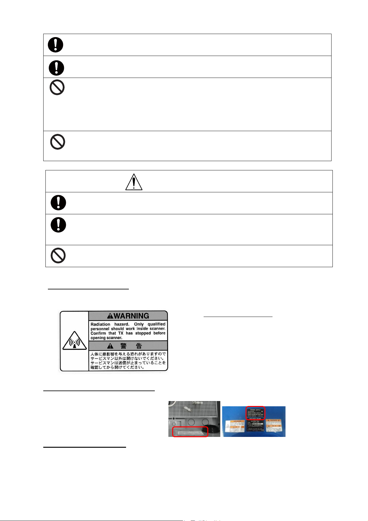
Antenna Unit (radome)
Name: Radiation Warning Label
Type : 03-142-3201-0
number : 100-266-890-10
WARNING LABEL
Warning labels are attached to the equipment. Do not remove any label.
If a label is missing or damaged, contact us for the replacement.
POWER SUPPLY LABEL
100-240 VAC
SINGLE PHASE, 50/60 Hz
POWER CONSUMPTION: MAX Watt
RATED AMPERE
WR110 restrictions
There are restrictions frequency band as follows to use at Lithuania and Slovakia.
WR110 is operated with a channel from the following four channels:
CH1: 9422.5MHz, CH2: 9427.5MHz, CH3: 9432.5MHz, CH4: 9437.5MHz
ii

S2E-17-0056_A
WEATHER RADAR
WR110
Contents:
SAFETY INSTRUCTIONS .................................... i
System Configuration ......................................... iv
1. System Summary ......................................... 1
2. Equipment Configuration
2.1. Standard Equipment of WR110 ............ 3
2.2. Optional accessories for installation ..... 4
2.3. Construction materials list ..................... 4
2.4. Overall appearance ............................. 4
3. Prior confirmation
3.1. Confirmation items ................................ 5
3.2. Power equipment ................................ 5
3.3. Measurements ...................................... 5
3.4. LAN equipment ..................................... 5
3.5. Peripherals equipment .......................... 6
4. Precautionary item ........................................... 7
5. Construction
5.1. Antenna Unit ......................................... 8
5.2. Junction Unit ....................................... 14
5.3. Data Processing Unit ......................... 14
5.4. Open the radome temporary ............. 15
6. Operation Test
6.1. Before cover ........................................ 16
6.2. After cover ........................................... 17
7. Install TeamViewer ........................................ 18
8. DPU operation
8.1. File ....................................................... 20
8.2. Disp ..................................................... 20
8.3. Setting
8.3.1. Setting ...................................... 21
8.3.2. Service ...................................... 26
8.3.3. Precipitation estimates methods
.......................................................... 29
8.3.4. Management list ……………… 30
8.4. Radar Operation ..................................32
8.5. Help .....................................................33
8.6. Stop radar operation ........................... 33
8.7. RainPlay operation .............................. 34
8.8. Initial setting of Azimuth ...................... 37
8.9. Log file function ................................... 39
9. Menu Tree .................................................... 40
Installation manual
10. Specification
10.1. Antenna Unit ................................... 42
10.2. Data Processing Unit ..................... 43
11. UPS settings
11.1. APC product .................................... 44
11.1.1. Login ....................................... 45
11.1.2. Power Protection Strategy .... 45
12. Windows Language settings ...................... 48
13. Create map file for RainMap
13.1. Required software ........................... 50
13.2. Web Browser ................................... 50
13.3. Display ............................................. 50
13.4 Overview .......................................... 50
13.5 Create a map ................................... 51
13.5.1. Cut maps .............................. 51
13.5.2. Change color of map .............. 64
13.5.3. Confirm a created map ........... 70
13.5.4. Create a map license ............. 73
APPENDIX
1. Outline drawing .................................... 74
2. System diagram ..................................... 76
S2E-17-0056_A
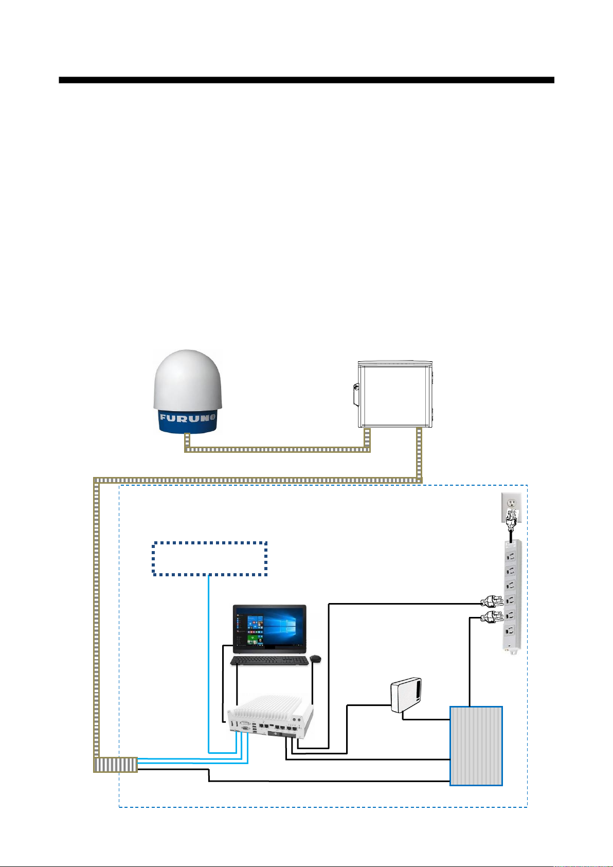
DPU
ATU
JCU
Indoor image
AC100-240
UPS
USB cable
AC100-240
AC cable
USB cable
Equipment for
internet
LAN cable x2
AC100-240
AC100-240
External data
storage device
AC100-240
LAN cable
* All equipment except DPU (w/ keyboard) is the local supply.
LAN cablex2 / AC cable
LAN cablex2 / AC cable
System Configuration
The observation system consists of an Antenna Unit (radome), a Signal Processing Unit
(connection box) , and a Data Processing Unit (indoor unit) are shown below.
(1) Antenna Unit (radome)
(2) The antenna, stored in the radome, turns to radiate the radio waves.
The radiated waves are backscattered by precipitation particles on the propagation path,
return to the antenna, and are processed by RF converter to transfer the signals to the Signal
Processing Unit .
(3) Signal Processing Unit (connection box)
Signal Processing Unit is stored in the connection box, and processes received signals
digitally.
The digitally-processed signals are transferred to the Data Processing Unit via 100Base-T
(LAN) .
(4) Data Processing Unit (indoor unit)
Data Processing Unit is displaying and operating the weather radar.
Consumer must prepare the external storage device for recording the weather observation data
if necessary.
iv
S2E-17-0056_A
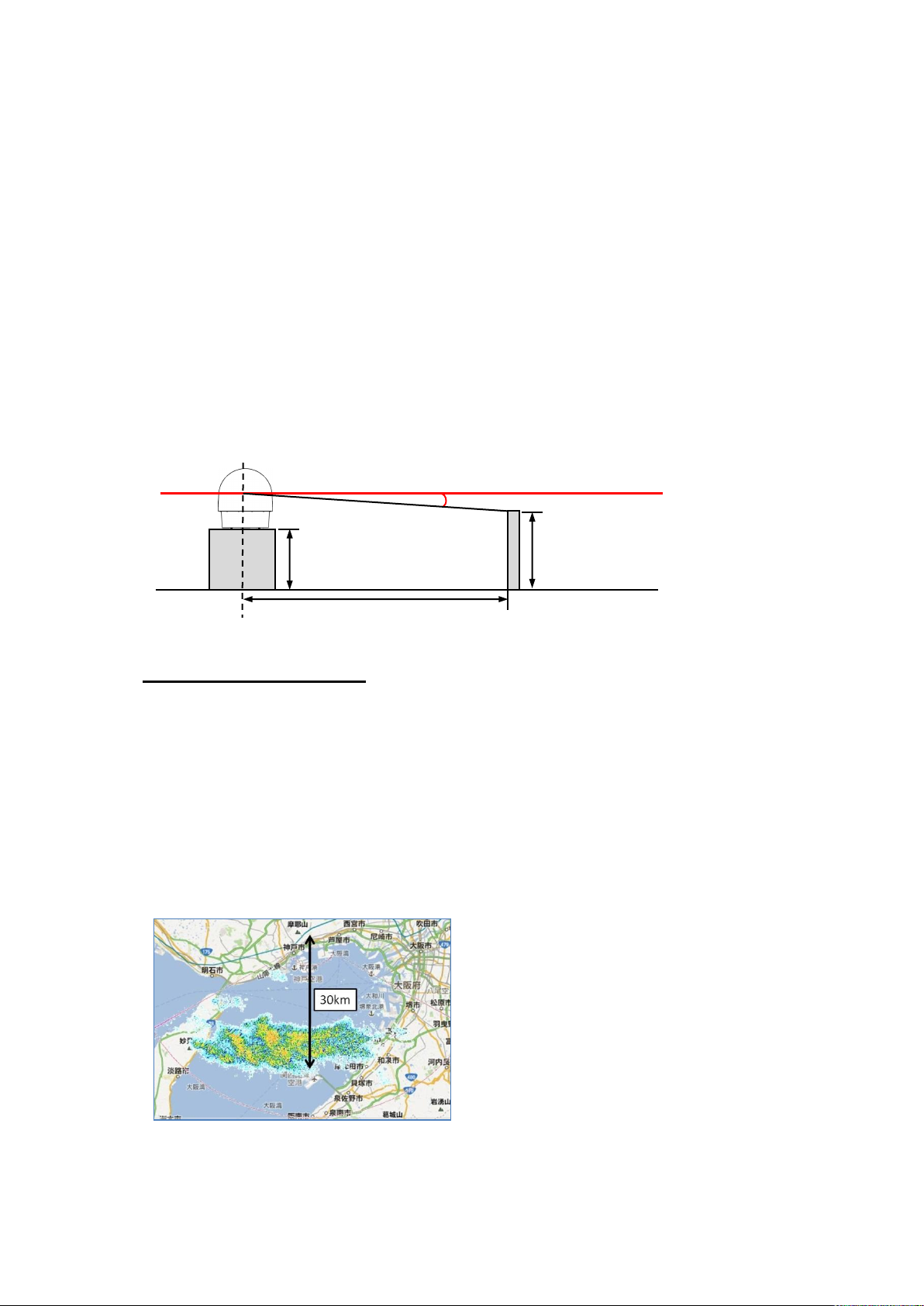
θ
H1
d
H2
H
1
> H
2
- 0.6 + d・tan0
1. System Summary
This system observes the development of rain clouds, outputs the strength of precipitation
and the speed of rain clouds (Doppler speed), and observes phenomena of rainfall.
Features:
1. While installing antenna on a rooftop of building in urban area, it must be installed in the
safety area covered by lightning rod based on JIS A4201 and IEC61024-1.
2. Nothing should be surrounded around the antenna area.
Safe distance:
- If H1 is taller than 2.2 meters, it is safe unless touch the antenna directory.
- If H1 is shorter than 2.2 meters, do not enter within a radius of 13meters from the
antenna.
Notice: It based on the standard of 2 meters tall person.
Safety zone around radar
e.g.: H2 (Height) = 2m,
d (Distance between center of the antenna and human) = 13m,
θ =3.5° (Minimum elevation is -2°+ a half of beam width 1.5°)
H2-0.6+d・tanθ = 2-0.6+13・tan3.5°=2.195m<H1
Therefore, H1 (Height of base) = 2.2m,
3. High Resolution Rain Observation, Rain Cloud, Density and Speed Observation.
4. Solid-state Transmitter replaces an aging device such as a magnetron.
1
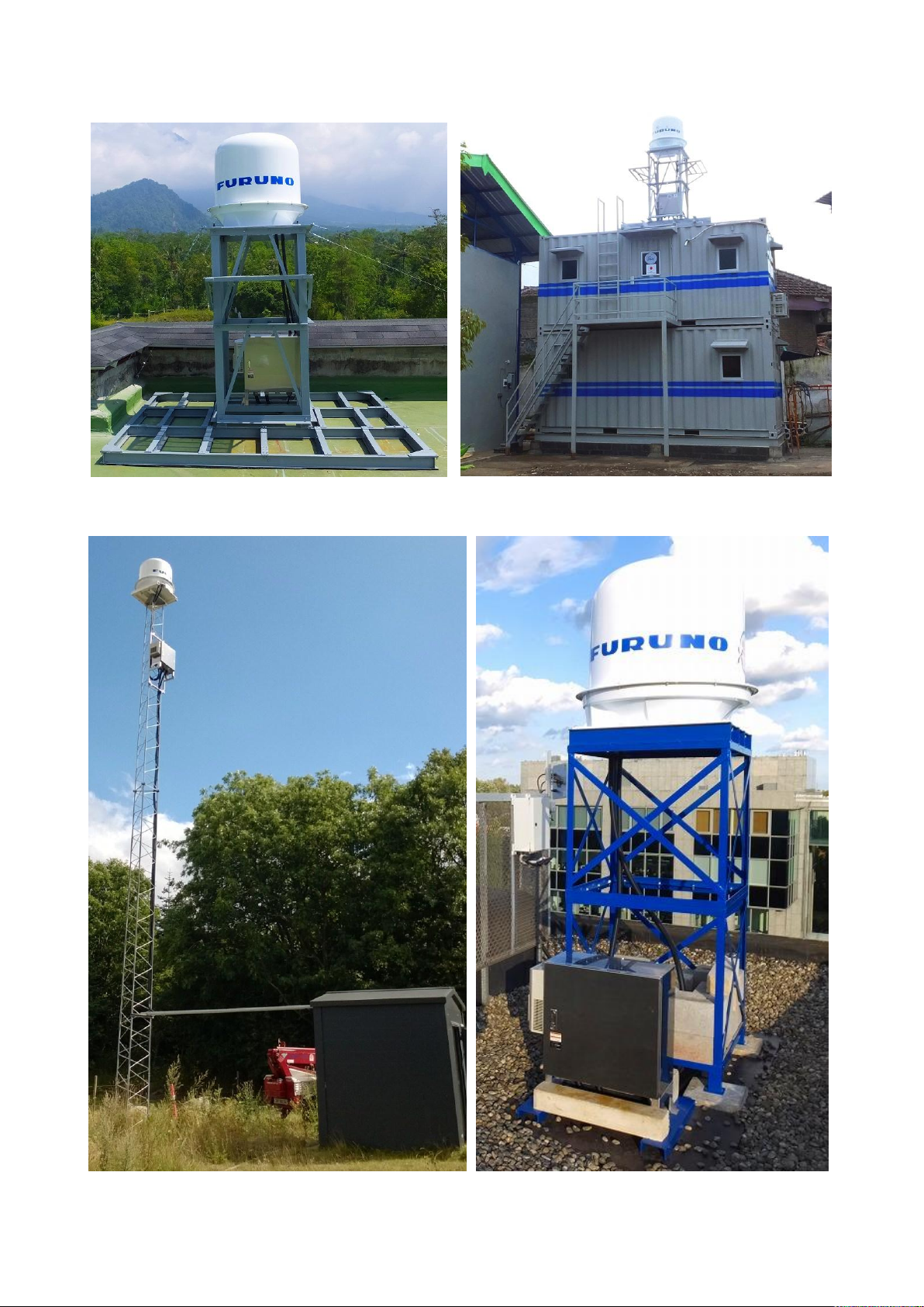
Sample image of WR-2100
Indonesia
Indonesia
Denmark
Belgium
S2E-17-0056_A
2
2. Equipment configuration
MODEL
TYPE
WEATHER RADAR
WR110
Main Unit
Items
Units
Descriptions
Qty
Antenna Unit
WR110 -ATU
Size : Ф980mm×H1068mm (include radome)
Weight : 65Kg
Weight of radome only: Upper 15kg (incl. 12pcs
of M10x35 stopper hexagon bolt), Bottom 11kg
1
Junction Unit
WR110 -JCU
Size: W330 x D130x H336mm (connection box)
Weight: 2.0kg
Incl. Fixing band (φ26-101, W20mm), M4x35mm
screw
1
Data Processing Unit
WR110 -DPU
Unspecified. Keyboard is included.
Note: Please prepare mouse and display
separately because these are excluded.
1
Cables & Tube
Antenna Unit (radome) --- Junction Unit
Items
Descriptions
Length
Qty
LAN cable
100Base-T (STP Cat5e or better), Length depends on
measure value. Incl. LAN connector w/ cover
5m
(*1)
2
AC Power cable
Shielded VCTF 2sq 3core or equivalent
Incl. crimped Terminal
5m
(*1)
1
Protective tube
PF tube conduit Inner diameter : 28 mm
10m
(*2)
1
Accessories for installation (Fixed radome and stand)
Items
Descriptions
Qty
M16x200mm Hexagon Bolt
Material : SUS304
4
M16 Nut
Material : SUS304
12
M16 Split Lock Washers
Material : SUS304
4
M16 Flat Washers
Material : SUS304
8
M16 Large Flat Washers
Material : SUS304
4
Accessories for maintenance
Items
Descriptions
Qty
M10 x500 Stud Bolt Steel
Holding the radome cover up above in order to access
inside the radome when maintenance
6
M10 Nut
Fix the length of stud bold for lifting up the radome
6
M10 Slip on Lock Nut
Holding the radome cover up above in order to access
inside the radome when maintenance
6
2.1. Standard Equipment of WR110
S2E-17-0056_A
(*1)
Basic length of cable is 5m, and there are 10m, 15m, 20m for option.
(*2)
Cut into two pieces to adjust a length of protective tube between ATU and JCU.
Note: For the stand of radar depends on installation environment, therefore consultation will be
necessary.
3
2.2. Optional accessories for installation (Set of lifting tool)
Items
Descriptions
Qty
Lifting tool for radome
Size: 1000mm x 1018mm x 40mm, Weight: 10kg
1
M12 Eye bolt set
For lifting up radome by crane (incl. nut, washer)
4
M12x40mm bolt set
Incl. split lock washer, flat washer, nut.
4
M16 Nut
Material : SUS304 (Fixed between radome and stand)
8
M16 Split Lock Washers
Material : SUS304 (Fixed between radome and stand)
4
M16 Flat Washers
Material : SUS304 (Fixed between radome and stand)
8
Cables & Tube
Junction Unit --- Data Processing Unit
Items
Descriptions
Length
Qty
LAN cable
100Base-T (STP Cat5e or better), Length depends on
measure value. Incl. LAN connector w/ cover
by measure
2
AC power cable
Shielded VCTF 2sq 3core or equivalent.
Incl. crimped Terminal
by measure
1
Protective tube
PF tube conduit Inner diameter : 28 mm
by measure
2
Basic construction equipment
Items
Descriptions
Qty
Heavy Duty Cable Tie (2 types)
Nylon 6/6 w/ weather resistance 140mm, 300mm
100
Basic construction tool
Items
Descriptions
Hex key (Ball-head type)
M4 (3mm)
Ratcheting Wrench
M5 (8mm), M12 (19mm), M16 (24mm),
Adjustable wrenches (up to 30mm)
Socket Wrench
M10 (17mm) for fixing radome top/bottom
Exclusive Philips Screwdriver #1
Multiuse
Philips Screwdriver #2
Multiuse
Slotted Screwdriver 3mm
Multiuse
Cable/Wire cutting scissors
Multiuse
Flat nippers
Multiuse
Wire Strippers
For electric wiring work
Ratchet Wire Crimper 2sq
For electric wiring work
LAN cable strippers
For LAN cable work
LAN Ratchet Crimper
For LAN cable work
LAN cable tester
For LAN cable work
2.3. Construction material list (Local contractor/client supply)
S2E-17-0056_A
2.4. Overall appearance
Refer to the APPENDIX for Drawing of WR110
4
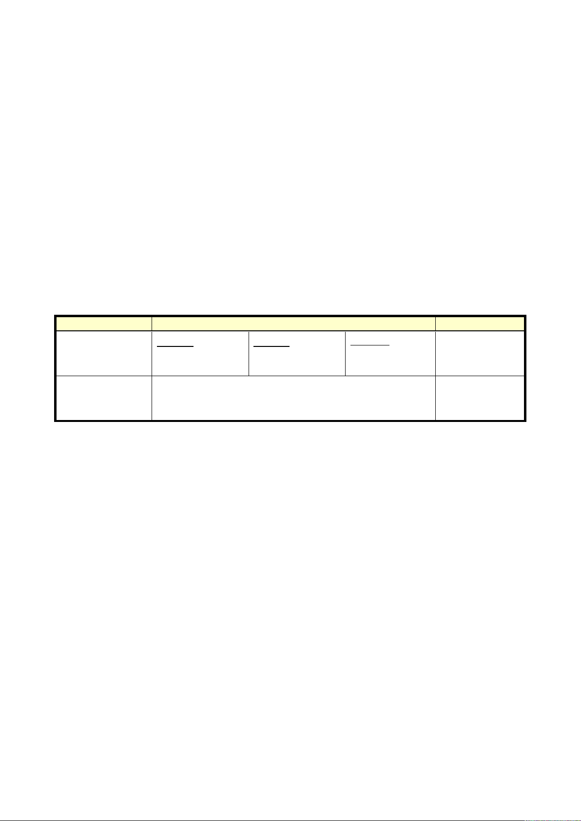
3. Prior confirmation
Items
Descriptions
Remarks
Digital Multimeter
Voltage
AC : 85 to 240 V
DC : 1 to 50V
Current
AC : 1 to 10 A
DC : 1mA to 1A
Resistor
0.1 to 10M ohm
Tester
Lead Cables
Angle Meter
Measurement range : ≧ 45deg
Accuracy : within ±0.2deg
Levelling of radar
3.1. Confirmation items
1. The mount plate must be installed properly for Antenna Unit (radome).
2. Power cable (AC100V-240V) must be laid safely.
3. Power cable thickness should be selected depends on its length.
4. Frequency of AC power source must be 50Hz or 60Hz sin wave and single-phase current.
5. All engineers must wear the safety appliances such as a helmet, and safety shoes during an
installation of Antenna Unit. It is very dangerous that Antenna might hit a head by turning.
DO NOT look the antenna closer while radar is in operation. This energy can extremely
damage to the human body and especially to the eyes. Furthermore, DO NOT point the
antenna to the people closer while transmitting.
* As shown in the beginning of warning (Table on page i, Radio Frequency Radiation Hazard),
the distance of transmit radio wave to be 100W/m2, 50W/m2, 10W/m
standard is 10W/m2, do not go closer than 12.7m to the radar.
3.2. Power equipment
This equipment must need 1KVA x1 line of power, with ground outlet (3 pin type)
3.3. Measurements
S2E-17-0056_A
2
. The value of safe
3.4. LAN equipment
1) Use Cat5e (or better grade) of 100Base-Tx LAN cable for transferring the data from the Data
Processing Unit to output equipment.
2) Be prepared High speed broadband (approx.100Mbps) for using remote maintenance.
*Low speed broadband may cause slow access on remote to support a system.
5

3.5. Peripherals equipment
Function
Connect with an external network
WAN port
10/100/1000BASE-T, 1 port, MDI/MDI-X auto switch
LAN port
10/100/1000BASE-T, 4 port or more, MDI/MDI-X auto switch
Input voltage
AC100V-240V, Single phase, 50/60 Hz
Remarks
YAMAHA RTX810 or equivalent
Function
Connect with LAN
LAN port
10/100/1000BASE-T, 5 port or more, MDI/MDI-X auto switch
Input voltage
AC100-240V, Single phase, 50/60 Hz
Remarks
ELECOM EHC-G05MN-HJ or equivalent
Function
Automatically shut down after 10 minutes operation during a power
failure
Output voltage
More than 1,000VA
Input voltage
AC100-240V, Single phase, 50/60 Hz
Remarks
APC Smart-UPS series w/ network or equivalent
Function
Save scan data
Capacity
3TB or more
Interface
USB3.0 (Note: Plug in USB3.0 cable in to the USB3.0 port of DPU)
Input voltage
AC100-240V, Single phase, 50/60 Hz
Remarks
WD 3TB or equivalent
Function
Reboot the power of equipments by remote
Capacity
2-4 individual outlet power control (ON/OFF/Reboot/Schedule)
Interface
10BASE-T/100BASE-TX RJ-45X1, RS232
Input voltage
AC100-240V, Single phase, 50/60 Hz
Remarks
AVIOSYS IP POWER series or equivalent
The purposes of using these peripherals are for remote control:
1. Wired router
2. SW HUB
3. Uninterruptive Power Supply
S2E-17-0056_A
4. External data storage device
5. Remote Power Controller
6

S2E-17-0056_A
Radar stand
ATU
Angle of the radar stand should be levelling within ±2 degrees.
Levelling ±0.2°
(Radar)
Levelling ±2°
(Radar stand)
4. Precautionary item
1) Use only the commercial power supply of single phase 100-240VAC.
2) DO NOT overhaul or remodel.
3) DO NOT work during the thunder is occurring.
4) DO NOT scratch, cut, forcedly bend, pull, twist, bundle, or damage the power cable. Also, not to
put a heavy thing on top or interpose.
5) DO NOT touch inside equipment with a wet hand.
6) Connect the ground conductor for protecting equipment and electric shock prevention from
lightning induction and ground leakage.
7) Cleaning instruction: Use dried soft cloth to wipe the surface. If it is difficult to remove stains, use
the cloth soak with a neutral detergent to clean it. Please DO NOT use an alcohol or an organic
solvent (e.g.: thinner) to clean it.
For optional equipment:
Please refer to attached documents of UPS, Router, and other equipment separately.
7
S2E-17-0056_A
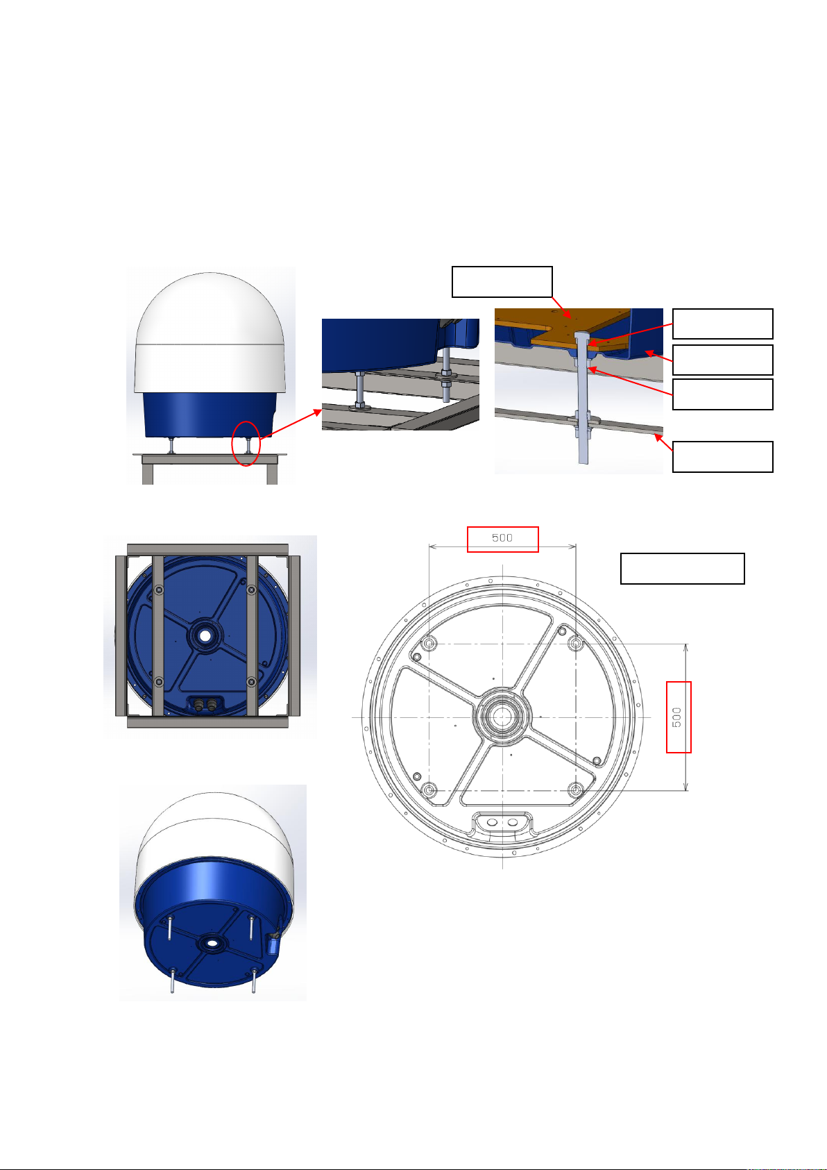
M16 bolt
Radome
M16 Nuts
Radar stand
Base plate
Size: 500x500
5. Construction
All installation places will be considered for installing DPU, cables, pipes, and mount plate during
the environmental survey.
5.1. Antenna Unit
<Case 1>
A way of using a frame stands to mount the Antenna Unit.
Use 4 pieces of M16x200 Bolts to adjust a level while join and fix the lifting tool and a frame stand.
8
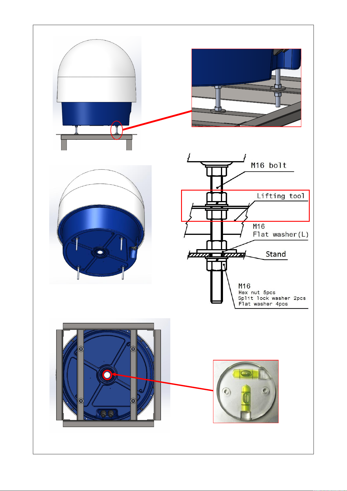
1. Levelling the Antenna Unit
Check with the bubble level under the radar
to turn M16 hex nut (Fig.5-2) for adjusting
the level of radar.
Fig. 5-1. Under the radar
Fig. 5-2. M16 bolt
*1
*1: These hex nuts, flat washers, split lock
washers are attached with the lifting tool
(optional).
S2E-17-0056_A
9

After leveling the radar, make sure to confirm every four nut touches to the top of the stand before
pinching the stand from the bottom, i.e. between ①nut, ②XL flat washer, and ③radar stand are not
having gap before tighten the ④nut, in order not to strain the radome and stand.
①nut
②XL flat washer
④nut
③Radar stand
NG
OK
S2E-17-0056_A
10
S2E-17-0056_A
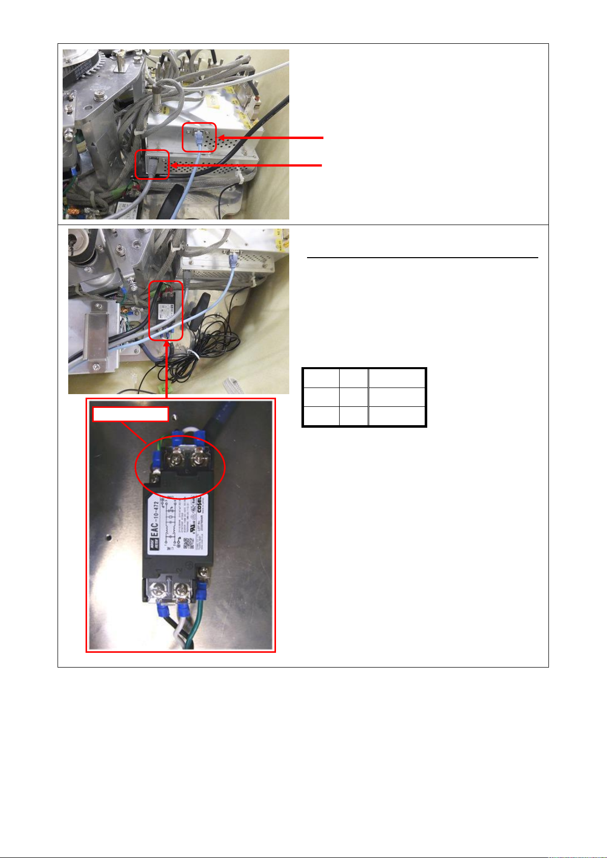
2. Connect LAN cable for MONI-CON and SPU
3. Wire the power filter
Caution: Make sure an electric current is not flow
(1) Fix / Connect AC power cable (3pin)
(2) Confirm the circuit diagram of power filter
label before connecting.
(3) Connect the LINE side to match with the line
color of LOAD side and LINE side.
<Wire color>
P/L + Black
N - White
GND
FG
Green
P/L: Phase/Live
N: Neutral
E: Earth / Ground
SPU LAN connector
MONI-CON LAN connector
Power filter
11
S2E-17-0056_A
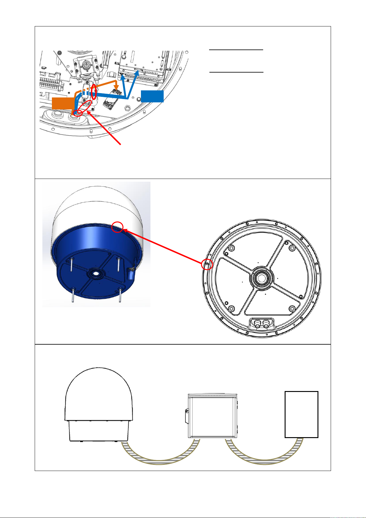
4. Insert the outdoor cable into the
protecting tube (2 pcs).
Protecting Tube 1:
- C1: AC Power cable (3cores)
- C2: LAN cable x2
Protecting Tube 2:
Cover by cap
※ Fix cables tight by cable ties with having
extra cable length after connected
cables.
5.Cover the top of radome
- Fix the bottom part of radome by 12
pcs of M10x35 Hex Bolts. These are
using a dropout prevention fixed bolts.
6. Every location must have to measure a length in between ATU JCU DPU for
adjustment. And to lay the Protecting Tube.
ATU
DPU
(Indoor)
JCU
C1
C2
Fix cables by cable ties.
12
 Loading...